Page is loading ...

7700 MultiFrame Manual
7703PA, 7703PA-LNB, 7703PA-2 RF Amplifier with Slope Compensation
Revision 1.0
TABLE OF CONTENTS
1. OVERVIEW.......................................................................................................................................... 1
2. INSTALLATION................................................................................................................................... 3
3. SPECIFICATIONS............................................................................................................................... 4
3.1. RF INPUT ................................................................................................................................... 4
3.2. RF OUTPUT................................................................................................................................ 4
3.3. ELECTRICAL ............................................................................................................................. 4
3.4. PHYSICAL (NUMBER OF SLOTS)............................................................................................ 5
4. STATUS INDICATORS AND DISPLAY.............................................................................................. 6
4.1. CARD EDGE LEDS.................................................................................................................... 6
4.2. DOT-MATRIX DISPLAY............................................................................................................. 7
4.2.1. Setting the Input RF Alarm Threshold Levels ....................................................................... 9
4.2.2. Setting the Gain Mode .......................................................................................................... 9
4.2.3. Setting the Gain .................................................................................................................. 10
4.2.4. Setting the AGC RF Output Target Level............................................................................ 10
4.2.5. Setting the Slope Correction Level...................................................................................... 10
4.2.6. LNB Voltage Level .............................................................................................................. 11
4.2.7. 22KHz Tone ........................................................................................................................ 12
4.2.8. LNB Current Threshold Levels............................................................................................ 12
4.2.9. Default Card-Edge Display.................................................................................................. 12
4.2.10. Setting the Display Orientation............................................................................................ 12
4.2.11. Displaying the RF Input Power............................................................................................ 13
4.2.12. Displaying the RF Input Alarm Thresholds.......................................................................... 13
4.2.13. Displaying the Gain Mode Setting....................................................................................... 13
4.2.14. Displaying the Gain Setting................................................................................................. 13
4.2.15. Displaying the AGC Output Power Target Level................................................................. 14
4.2.16. Displaying the Slope Correction Level ................................................................................ 14
4.2.17. Displaying the LNB Voltage Level....................................................................................... 14
4.2.18. 22KHz Tone Status ............................................................................................................. 14
4.2.19. Displaying the LNB Current................................................................................................. 14
4.2.20. Displaying the LNB Current Threshold Level ...................................................................... 15
4.2.21. Displaying the Firmware Version ........................................................................................ 15
5. JUMPERS AND USER ADJUSTMENTS.......................................................................................... 16
5.1. SELECTING WHETHER LOCAL FAULTS WILL BE MONITORED
BY THE GLOBAL FRAME STATUS........................................................................................ 16
5.2. CONFIGURING THE MODULE FOR FIRMWARE UPGRADES ............................................. 17

7700 MultiFrame Manual
7703PA, 7703PA-LNB, 7703PA-2 RF Amplifier with Slope Compensation
Revision 1.0
5.3. FACTORY AND BDM JUMPERS............................................................................................. 17
6. VISTALINK® REMOTE MONITORING/CONTROL........................................................................... 18
6.1. WHAT IS VISTALINK®?............................................................................................................. 18
6.2. VISTALINK® MONITORED PARAMETERS.............................................................................. 19
6.3. VISTALINK® CONTROLLED PARAMETERS........................................................................... 19
6.4. VISTALINK® TRAPS.................................................................................................................. 20
Figures
Figure 1-1: 7703PA, 7703PA-LNB, 7703PA-2 Block Diagram ............................................................................. 2
Figure 2-1: 7703PA, 7703PA-LNB and 7703PA-2 Rear Plates............................................................................ 3
Figure 4-1: Approximate Frequency Response Characteristics with Different Slope and Gain Levels ............. 11
Figure 5-1: Jumper / LED Locations ................................................................................................................... 16
Tables
Table 4-1: Card Edge Menu Structure .................................................................................................................. 9
Table 6-1: VistaLINK® Monitored Parameters..................................................................................................... 19
Table 6-2: VistaLINK® Controlled Parameters .................................................................................................... 19
Table 6-3: VistaLINK® Traps ............................................................................................................................... 20

7700 MultiFrame Manual
7703PA, 7703PA-LNB, 7703PA-2 RF Amplifier with Slope Compensation
Revision 1.0
REVISION HISTORY
REVISION DESCRIPTION DATE
1.0 First Release May 2010
Information contained in this manual is believed to be accurate and reliable. However, Evertz assumes no responsibility for the use thereof nor for
the rights of third parties, which may be affected in any way by the use thereof. Any representations in this document concerning performance of
Evertz products are for informational use only and are not warranties of future performance, either expressed or implied. The only warranty offered
by Evertz in relation to this product is the Evertz standard limited warranty, stated in the sales contract or order confirmation form.
Although every attempt has been made to accurately describe the features, installation and operation of this product in this manual, no warranty is
granted nor liability assumed in relation to any errors or omissions unless specifically undertaken in the Evertz sales contract or order confirmation.
Information contained in this manual is periodically updated and changes will be incorporated into subsequent editions. If you encounter an error,
please notify Evertz Customer Service department. Evertz reserves the right, without notice or liability, to make changes in equipment design or
specifications.

7700 MultiFrame Manual
7703PA, 7703PA-LNB, 7703PA-2 RF Amplifier with Slope Compensation
Revision 1.0
This page left intentionally blank

7700 MultiFrame Manual
7703PA, 7703PA-LNB, 7703PA-2 RF Amplifier with Slope Compensation
Revision 1.0 Page - 1
1. OVERVIEW
The 7703PA series provide amplification of RF signals in the satellite extended L-Band range. Adjustable
slope compensation is included. Typical applications include amplification and slope compensation to
boost weak signals, drive long coax runs or provide a high power signal for passive distribution systems.
All models occupy one card slot and can be housed in a 1RU frame, which holds up to 3 modules, a 3 RU
frame which holds up to 15 modules or a standalone enclosure, which holds a single module.
Features:
• Can be used as a wideband amplifier without slope compensation for signals from 40-2300MHz or as
an amplifier with slope compensation for extended L-Band signals from 950-2150MHz
• Wide dynamic range (-10 to -60dBm)
• Protocol independent - handles all modulation formats
• Up to 0dBm output with low IMD
• Fully hot-swappable from front of frame
• Comprehensive signal and card status monitoring via four digit card edge display
• Up to 30 dB gain, adjustable in 0.5 dB steps
• AGC mode with adjustable target level to maintain a constant output level with varying input
• Cable slope compensation, adjustable up to 15dB in 1dB steps
• RF input power monitoring
• Remote monitoring through SNMP and VistaLINK® capability
7703PA:
• Single channel amplifier
7703PA-LNB:
• Single channel amplifier with built-in LNB power up to 400mA
• LNB power is 13/18VDC adjustable with built-in current limiting, current monitoring and 22KHz tone
for LO control
7703PA-2:
• Dual channel amplifier

7700 MultiFrame Manual
7703PA, 7703PA-LNB, 7703PA-2 RF Amplifier with Slope Compensation
Page - 2 Revision 1.0
Figure 1-1: 7703PA, 7703PA-LNB, 7703PA-2 Block Diagram

7700 MultiFrame Manual
7703PA, 7703PA-LNB, 7703PA-2 RF Amplifier with Slope Compensation
Revision 1.0 Page - 3
2. INSTALLATION
The 7703PA and 7703PA-LNB both come with a companion rear plate that has 2 BNC type 75 Ohm
connectors (F type, 50 Ohm BNC and SMA connectors are optional). The 7702PA-2 comes with a
companion rear plate that has 4 connectors. For information on mounting the rear plate and inserting the
module into the frame, see section 3 of the 7700FR chapter.
Figure 2-1: 7703PA, 7703PA-LNB and 7703PA-2 Rear Plates
RF IN: Input connector for satellite extended L-Band or wideband RF signals. This signal can be
any modulation format. See section 3.1 for further details.
RF OUTPUT: One or two (7703PA-2) connectors with the output signal having applied gain and slope as
set by the user.

7700 MultiFrame Manual
7703PA, 7703PA-LNB, 7703PA-2 RF Amplifier with Slope Compensation
Page - 4 Revision 1.0
3. SPECIFICATIONS
3.1. RF INPUT
Number of Inputs:
7703PA: 1
7703PA-LNB: 1
7703PA-2P: 2
Connector: BNC per IEC 61169-8 Annex A (F-Type, 50 Ohm BNC and SMA optional)
Impedance: 75Ω (50Ω optional)
Frequency Range: 950-2150MHz with slope control
40-2300MHz with no slope compensation added
Return Loss:
950-2150MHz: >15dB
40-2300MHz: >10dB
Input Power Range: -10dBm to -60dBm
LNB Power:
Voltage: 13V DC, 18V DC, off (selectable)
Current: 400mA
Protection: Short circuit, current limited
LO Control: 22kHz on/off (selectable)
3.2. RF OUTPUT
Number of Outputs:
7703PA: 1
7703PA-LNB: 1
7703PA-2P: 2
Connector: BNC per IEC 61169-8 Annex A (F-Type, 50 Ohm BNC and SMA optional)
Impedance: 75Ω (50Ω optional)
Return Loss: > 20dB
Gain: 0 - 30dB, adjustable in 1/2db steps
Slope: Adjustable, up to 15dB in 1dB steps across 950-2150MHz
IMD: < -45dBC (0dBm out, 10dB gain)
< -50dBC (0dBm out, 20dB gain)
< -55dBC (0dBm out, 30dB gain)
P1dB: +3dBm
Frequency Response (no slope applied):
950-2150MHz: ± 0.5dB
40 - 2300MHz: ± 2dB
3.3. ELECTRICAL
Voltage: +12V DC
Power:
7703PA: 6 Watts
7703PA-LNB: 15 Watts
7703PA-2: 12 Watts

7700 MultiFrame Manual
7703PA, 7703PA-LNB, 7703PA-2 RF Amplifier with Slope Compensation
Revision 1.0 Page - 5
3.4. PHYSICAL (NUMBER OF SLOTS)
7700FR-C: 1
7800FR: 1
7701FR: 1

7700 MultiFrame Manual
7703PA, 7703PA-LNB, 7703PA-2 RF Amplifier with Slope Compensation
Page - 6 Revision 1.0
4. STATUS INDICATORS AND DISPLAY
4.1. CARD EDGE LEDS
Two large LEDs on the front of the board indicate the general health and alarm status of the module:
MODULE OK: This Green LED will be On when the module is operating properly and not extending
any alarms.
LOCAL FAULT: This Red LED will be On when there is a fault in the module power supply, or any
alarm conditions are present (i.e. RF input power or LNB current above or below
alarm threshold settings)
There are 9 small LEDs below the two large LEDs that indicate the status of the module:
LED Indication Function
RED RF Input Power Channel 1 is greater then or equal to the upper threshold
setting.
1 OFF RF Input Power Channel 1 is less then the upper threshold setting.
GREEN RF Input Power Channel 1 is less then the upper threshold setting and
greater then the lower threshold setting.
2 OFF RF Input Power Channel 1 is less then the lower threshold setting or
greater then the upper threshold setting.
YELLOW RF Input Power Channel 1 is less then or equal to the lower threshold
setting.
3 OFF RF Input Power Channel 1 is greater then the lower threshold setting.
RED AGC Channel 1 is on but unable to maintain output power setting.
GREEN AGC Channel 1 is on and can maintain output power setting.
4
OFF AGC Channel 1 is off (manual mode).
RED RF Input Power Channel 2 is greater then or equal to the upper threshold
setting.
5 OFF RF Input Power Channel 2 is less then the upper threshold setting.
GREEN RF Input Power Channel 2 is less then the upper threshold setting and
greater then the lower threshold setting.
6 OFF RF Input Power Channel 2 is less then the lower threshold setting or
greater then the upper threshold setting.

7700 MultiFrame Manual
7703PA, 7703PA-LNB, 7703PA-2 RF Amplifier with Slope Compensation
Revision 1.0 Page - 7
YELLOW RF Input Power Channel 2 is less then the lower threshold setting or
greater then the upper threshold setting.
7 OFF RF Input Power Channel 2 is less then the lower threshold setting or
greater then the upper threshold setting.
RED AGC Channel 2 is on but unable to maintain output power setting.
GREEN AGC Channel 2 is on and can maintain output power setting.
8
OFF AGC Channel 2 is off (manual mode).
RED LNB SHORT (FAULT)
GREEN LNB OK (NO FAULT)
9
OFF LNB OFF
4.2. DOT-MATRIX DISPLAY
Additional signal and status monitoring and control over the card’s parameters are provided via the 4-digit
alphanumeric display located on the card edge. To select one of two menu display modes, press the
toggle switch. To go to the sub-menu press the pushbutton once and press the toggle switch to select the
sub-menu. When in a particular display mode, press the pushbutton to display the value and use the
toggle switch to change values (if applicable) and to see what status is being displayed for the particular
menu item. Table 4-1 provides a quick reference to the display menu structure.

7700 MultiFrame Manual
7703PA, 7703PA-LNB, 7703PA-2 RF Amplifier with Slope Compensation
Page - 8 Revision 1.0
Level 1 Level 2 Level 3 Level 4 Level 5 Level 6
BACK
BACK
CH1
LWR CH2
0 to -60 dBm
Default: -60 dBm
CH1
RFTH
UPPR CH2
0 to -60 dBm
Default: 0 dBm
CH1 MAN (default)
MODE CH2 AGC
CH1
GAIN (visible in
manual mode
only) CH2
0 to 30dB
default: 0dB
CH1
OUTL (visible
in AGC mode
only) CH2
0 to -50dBm
default: -20dBm
CH1
DEFD
selection CTRL
SLP CH2
0-15
default: 0
18
13
LNBV (visible
only on –LNB
version) OFF
ON
22KT (visible
only on –LNB
version) OFF
LWR 0 to 500mA
default: 0 LNTH (visible
only on –LNB
version) UPPR 0 to 500mA
default: 500
Fault
status(default)
LNBC
CH1 PWR
DEFD
CH2 PWR
HORZ
DISP VERT (default)
BACK
CH1
PWR 0 to -60dBm CH2
CH1
LWR CH2 0 to -60 dBm
CH1
RFTH
UPPR CH2 0 to -60 dBm
CH1 AGC
STAT
MODE CH2 MAN

7700 MultiFrame Manual
7703PA, 7703PA-LNB, 7703PA-2 RF Amplifier with Slope Compensation
Revision 1.0 Page - 9
CH1
GAIN (visible in
manual mode
only) CH2 0 to 31.5dB
CH1
OUTL (visible
in AGC mode
only) CH2 0 to -50dBm
CH1
SLP CH2 0-15
18
13
LNBV (visible
only on –LNB
version) OFF
ON
22KT (visible
only on –LNB
version) OFF
LNBC (visible
only on –LNB
version)
0 to 500mA /
SHORT
LWR 0 to 500mA
LNTH (visible
only on –LNB
version) UPPR 0 to 500mA
VER Firmware Version
Table 4-1: Card Edge Menu Structure
4.2.1. Setting the Input RF Alarm Threshold Levels
The input RF level alarm thresholds can be set by entering into the RFTH menu. From here, the user can
select either the LWR or UPPR option and the CH1 or CH2 option. Toggling the switch will move through
a range of values in 1dBm increments. Hitting the pushbutton will select the displayed value.
CTRL
RFTH
LWR / UPPR
CH1 / CH2
0 to -60dBm
LWR Sets the lower RF threshold level. Default of -60dBm.
UPPR Sets the upper RF threshold level. Default of 0 dBm.
CH1 Channel 1 threshold.
CH2 Channel 2 threshold.
0 to -60dBm RF threshold range (in dBm units).
4.2.2. Setting the Gain Mode
To adjust the gain mode, enter the Mode menu setting. In AGC mode, the card will automatically apply up
to 30dB of gain to the input signal in order to maintain the AGC target output level (see section 4.2.4 for
information on setting this level). In manual gain control mode, the output level will be offset from the input
level by the amount of applied gain (see section 4.2.3 for information on setting the gain).

7700 MultiFrame Manual
7703PA, 7703PA-LNB, 7703PA-2 RF Amplifier with Slope Compensation
Page - 10 Revision 1.0
CTRL
MODE
CH1 / CH2
AGC
MAN
CH1 Channel 1 gain mode.
CH2 Channel 2 gain mode.
AGC Enables Automatic Gain Control mode.
MAN Enables manual control. (default)
4.2.3. Setting the Gain
CTRL
GAIN
CH1 / CH2
0 to 30dB
Sets the fixed amount of applied gain. Visible in manual mode only.
CH1 Channel 1 gain.
CH2 Channel 2 gain.
0 to 30dB RF gain range (in dB units). Default of 0dB.
4.2.4. Setting the AGC RF Output Target Level
The 7703PA can apply up to 30dB of gain in AGC mode and therefore will only be able to maintain the
AGC output target level as long as it is not more than 30dB higher than the applied input signal. If the
input signal level is outside of the AGC hold range, the card will apply maximum or minimum gain as
appropriate, and the output level will track the input until the input falls back with AGC hold range.
Note that the AGC target level is based on the signal without any slope applied. Adding slope
compensation will increase signal power at higher frequencies, therefore it may be necessary to lower the
AGC target level to compensate and maintain the desired output composite power level.
CTRL
OUTL
0 to -50dBm
Sets the RF output power target in AGC mode. Visible in AGC mode
only.
0 to -50dBm RF output power range. Default of -20dBm.
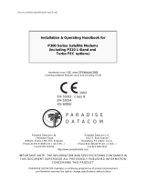
4.2.5. Setting the Slope Correction Level
The applied slope is optimized for signals in the L-Band or extended L-Band range from 950-2150MHz,
with the slope pivot point at 950MHz. Figure 4-1 illustrates the approximate frequency response of the
7703PA with different gain and slope levels applied.

7700 MultiFrame Manual
7703PA, 7703PA-LNB, 7703PA-2 RF Amplifier with Slope Compensation
Revision 1.0 Page - 11
40 MHz 2150 MHz950 MHz
0 dB
15 dB
0dB applied gain, 6dB applied slope
6 dB
0dB applied gain, 15dB applied slope
6dB applied gain, 0dB applied slope
6dB applied gain, 15dB applied slope
21 dB
0dB applied gain, 0dB applied slope
Figure 4-1: Approximate Frequency Response Characteristics
with Different Slope and Gain Levels
CTRL
SLP
CH1 / CH2
0 to 15
Sets the amount of RF slope correction to be added.
CH1 Channel 1 slope.
CH2 Channel 2 slope.
0 to 15 RF slope range. Default of 0.
4.2.6. LNB Voltage Level
CTRL
LNBV
18V
13V
OFF
Sets the LNB output voltage. Visible on -LNB versions only.
18V Sets the LNB output voltage to 18 volts.
13V Sets the LNB output voltage to 13 volts.
OFF Disables the LNB output voltage.

7700 MultiFrame Manual
7703PA, 7703PA-LNB, 7703PA-2 RF Amplifier with Slope Compensation
Page - 12 Revision 1.0
4.2.7. 22KHz Tone
CTRL
22KT
ON
OFF
Enables the 22KHz tone on the LNB voltage output. Visible on -LNB
versions only. The default setting is OFF.
ON Enables the 22KHz tone.
OFF Disables the 22KHz tone.
4.2.8. LNB Current Threshold Levels
CTRL
LNTH
LWR / UPPR
0 to 500mA
LWR Sets the low LNB current alarm threshold. Default of 0.
UPPR Sets the high LNB current alarm threshold. Default of 500.
0 to 500mA RF threshold range.
4.2.9. Default Card-Edge Display
This allows the user to select which operating condition will be the top-level item on the dot-matrix display.
The default is NORM, which displays “OK” as long as local power to the board is available. The table
below provides a list of alternate parameters.
CTRL
DEFD
NORM
LNBC
CH 1 / CH 2
PWR
NORM Local power status.
LNBC Measured LNB current.
CH1 RF Input Power Channel 1.
CH2 RF Input Power Channel 2.
PWR Measured RF Input power, channel 1 or channel 2 as
selected above.
4.2.10. Setting the Display Orientation
The DISP option allows the user to set a horizontal or vertical orientation for the card edge display. To set
the display orientation, select the CTRL menu item in the first menu level, then use the toggle switch to
show the DISP menu selection and use the pushbutton to select it. Use the toggle switch to change
between HORZ and VERT. Press the push button to make your selection.
CTRL
DISP
HORZ
VERT
HORZ Horizontal display used when the module is housed in the
one-rack unit 7701FR frame or the stand-alone enclosure.
VERT Vertical display used when the module is housed in the three-
rack unit 7800FR frame.

7700 MultiFrame Manual
7703PA, 7703PA-LNB, 7703PA-2 RF Amplifier with Slope Compensation
Revision 1.0 Page - 13
4.2.11. Displaying the RF Input Power
The 7703PA detects the RF input power level and displays this on the four-digit card edge display. Note
that this power level is a measure of the total composite signal power entering the card.
STAT
PWR
0 to -60dBm
CH 1 / CH 2
Displays the RF input power level.
0 to -60dBm RF input power range (in dBm units).
CH1 RF Input Power Channel 1.
CH2 RF Input Power Channel 2.
4.2.12. Displaying the RF Input Alarm Thresholds
STAT
RFTH
LWR / UPPR
0 to -60dBm
CH 1 / CH 2
LWR Indicates the low RF alarm threshold level.
UPPR Indicates the high RF alarm threshold level.
0 to -60dBm RF threshold range (in dBm units).
CH1 Channel 1 threshold.
CH2 Channel 2 threshold.
4.2.13. Displaying the Gain Mode Setting
STAT
MODE
CH 1 / CH 2
AGC
MAN
Indicates whether the gain mode setting is in AGC or manual.
CH1 Channel 1 gain mode.
CH2 Channel 2 gain mode.
4.2.14. Displaying the Gain Setting
STAT
GAIN
CH 1 / CH 2
0 to 31.5 dB
Indicates the amount of gain applied to the input signal. Visible in manual
mode only.
CH1 Channel 1 gain.
CH2 Channel 2 gain.
0 to 31.5 dB RF gain range (in dB units).

7700 MultiFrame Manual
7703PA, 7703PA-LNB, 7703PA-2 RF Amplifier with Slope Compensation
Page - 14 Revision 1.0
4.2.15. Displaying the AGC Output Power Target Level
STAT
OUTL
CH 1 / CH 2
0 to -50dBm
Indicates the RF output power target in AGC mode. Visible in AGC mode
only.
CH1 Channel 1 AGC target.
CH2 Channel 2 AGC target.
0 to -50dBm RF output power range.
4.2.16. Displaying the Slope Correction Level
CTRL
SLP
CH1 / CH2
0 to 15
Displays the RF slope correction level.
CH1 Channel 1 slope.
CH2 Channel 2 slope.
0 to 15 Slope range in dB.
4.2.17. Displaying the LNB Voltage Level
STAT
LNBV
18V
13V
OFF
Indicates the LNB output voltage.
18V LNB output voltage is set to 18 volts.
13V LNB output voltage is set to 13 volts.
OFF LNB output voltage is disabled.
4.2.18. 22KHz Tone Status
STAT
22KT
ON
OFF
Indicates whether the 22KHz tone on LNB output is enabled or disabled.
Visible on -LNB versions only.
ON 22KHz tone is enabled.
OFF 22KHz tone is disabled.
4.2.19. Displaying the LNB Current
STAT
LNBC
0 to 500mA
Short
Indicates the LNB current. Visible for -LNB versions only.
0 to 500mA LNB current range.
Short Short on LNB DC supply.

7700 MultiFrame Manual
7703PA, 7703PA-LNB, 7703PA-2 RF Amplifier with Slope Compensation
Revision 1.0 Page - 15
4.2.20. Displaying the LNB Current Threshold Level
STAT
LNTH
LWR / UPPR
0 to 500
LWR Indicates the lower LNB current threshold level.
UPPR Indicates the upper LNB current threshold level.
0 to 500mA LNB current threshold range.
4.2.21. Displaying the Firmware Version
The VER display shows the firmware version and build number of the 7703PA(-LNB)(-2) firmware. The
message will scroll across the display.
For example: VER 1.0 BLD 067

7700 MultiFrame Manual
7703PA, 7703PA-LNB, 7703PA-2 RF Amplifier with Slope Compensation
Page - 16 Revision 1.0
5. JUMPERS AND USER ADJUSTMENTS
/ MODULE OK
LOCAL FAULT
AGC Status Ch2
DOT MATRIX DISPLAY
RF Ch1 High
RF Ch1 OK
RF Ch2 Low
RUN/UPGRADE
FRAME
STATUS
OFF/ON
J6
Serial Upgrade Port
Pushbutton
Toggle
Switch
BDM
FACTORY
AGC Status Ch1
RF Ch2 Low
RF Ch2 OK
RF Ch2 High
LNB Power Status
Figure 5-1: Jumper / LED Locations
5.1. SELECTING WHETHER LOCAL FAULTS WILL BE MONITORED
BY THE GLOBAL FRAME STATUS
The FRAME STATUS jumper J3, located at the front of the module determines whether local faults (as
shown by the Local Fault indicator) will be connected to the 7700FR frame's global status bus.
FRAME STATUS: To monitor faults on this module with the frame status indicators (on the PS FRAME
STATUS LED's and on the Frame's Fault Tally output) install this jumper in the On
position. On Rev 1 and A boards install the jumper. (default)
When this jumper is installed in the Off position local faults on this module will not
be monitored.
/