Page is loading ...

Installation Manual
For The
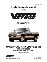
System #9022
UNDERHOOD AIR COMPRESSOR
TEL: 250-754-6997
FAX: 250-754-6972
TOLL FREE: 800-738-8622
1333 KIPP ROAD, NANAIMO, B.C. V9X 1R3
DOCUMENT 19632
1998-1999 FREIGHTLINER FL50, FL60, FL70, FL80
CATERPILLAR 3126 W/WOAC

Installation Manual Document 19632
VR7000 Underhood Air Compressor
System Number 9022
Application: 1998-1999 FREIGHTLINER FL50, FL60, FL70, FL80
CATERPILLAR 3126 W/WOAC
Publication Date: February 2001
Publication Number: 19632
Origination Documents: #19632 - introduction
#19632a - compressor and oil cooler installation
#19632b - air tank and line installation
#19632c- throttle controller installation
#19632d - control unit installation
#19633 - illustrated parts list
#19130 - warranty registration
Registered Trademarks:
VR7000 and Throttle Commander are registered trademarks of VMAC.
Freightliner is a registered trademark of Freightliner Corporation.
Caterpillar 3126 is a registered trademark of Caterpillar Inc.
Loctite, Prime N’ Clean, 242 and PST are registered trademarks of Loctite Corporation.
Nylok is a registered trademark of Nylok Fastener Corporation.
Copyright 2000
The contents of this manual may not be reproduced in any form without the express writ-
ten permission of VMAC

Contents
GENERAL INFORMATION ................................................................................................ 3
INTRODUCTION ......................................................................................................................... 5
INSTALLATION N OTES ............................................................................................................... 6
ORDERING PARTS ..................................................................................................................... 7
WARRANTY ............................................................................................................................. 7
CHANGES AND IMPROVEMENTS .................................................................................................. 7
PART 1: INSTALLING THE COMPRESSOR AND OIL COOLER ............................. 9
1.1 PREPARING FOR INSTALLATION .......................................................................................... 11
1.2 INSTALLING THE BRACKET AND COMPRESSOR ..................................................................... 11
1.3 INSTALLING THE OIL COOLER/THROTTLE CONTROLLER ASSEMBLY .......................................... 15
1.4 CONNECTING THE COOLING LINES ..................................................................................... 15
PART 2: INSTALLING THE AIR TANK AND LINES ................................................. 19
2.1 INSTALLING THE TANK MOUNTS AND THE TANK ................................................................... 21
2.2 CONNECTING THE AIR AND OIL LINES ................................................................................ 23
2.3 ADDING OIL TO THE SYSTEM ............................................................................................. 27
2.4 COMPLETING THE INSTALLATION ....................................................................................... 28
PART 3: INSTALLING THE CONTROL UNIT............................................................. 29
3.1 INSTALLING THE CONTROL UNIT ........................................................................................ 31
3.2 CONNECTING THE WIRING ................................................................................................. 32
PART 4: CONNECTING THE THROTTLE CONTROLLER ..................................... 35
4.1 CONNECTING THE CABLE .................................................................................................. 37
4.3 ADJUSTING THE CABLE .................................................................................................... 39
ILLUSTRATED PARTS LIST ............................................................................................ 41
WARRANTY REGISTRATION ........................................................................................ 47
1
DOCUMENT 19632

2

General Information
System #9022
1998-1999 FREIGHTLINER FL50, FL60, FL70, FL80
CATERPILLAR 3126 W/WOAC
UNDERHOOD AIR COMPRESSOR
3
DOCUMENT 19632

4

This symbol indicates that there is additional information or special emphasis
on a specific procedure.
This symbol indicates that there is a possibility of personal injury or damage to
the equipment if the indicated warning is not followed.
General Information
Introduction
This book provides installation instructions for:
VMAC underhood air compressor installation
VMAC Pneumatic Throttle Control connection and adjustment
This kit has been designed for:
1998-1999 FREIGHTLINER FL50, FL60, FL70, FL80
CATERPILLAR 3126 W/WOAC
Installation steps
The installation procedure in this manual has four main steps:
Part 1: Installing the Compressor and Oil Cooler
Part 2: Installing the Air Tank and Lines
Part 3: Installing the Control Unit
Part 4: Connecting the Pneumatic Throttle Control
Terms and symbols
This manual uses the following terms and symbols:
•OEM - Original Equipment Manufacturer
•HHCS - Hex Head Cap Screw (also called a hex bolt)
•SHCS - Socket Head Cap Screw (also called an Allen head bolt)
NOTE
WARNING
✁
5
DOCUMENT 19632

6
DOCUMENT 19632
STANDARD GRADE 8 NATIONAL COARSE THREAD
Size 1/4 5/16 3/8 7/16 1/2 9/16 5/8 3/4
Foot-pounds 9 18 35 55 80 110 170 280
STANDARD GRADE 8 NATIONAL FINE THREAD
Size 3/8 7/16 1/2 5/8 3/4
Foot-pounds 40 60 90 180 320
METRIC CLASS 10.9
Size M8 M10 M12 M14 M16
Foot-pounds 19 41 69 104 174
WARNING
✁
The above fastener torque values are applicable when Loctite is used .
If the threads are dry add 20% to the torque values.
Installation Notes
1. It is important that you complete all the installation steps before operating the system.
Refer to the Owner’s Manual before operating the system for the first time.
2. Follow all safety precautions for underhood mechanical work.
3. Use Loctite 242 or equivalent on all engine-mounted fasteners.
4. All hoses, tubes and wires which are re-routed or shifted during installation must be
secured so that they do not contact excessively hot areas or sharp edges. Where
possible, follow the routing instructions in this manual.
5. These installation instructions are intended as a general guide. In some instances, due
to variations in vehicle manufacture or if prior modifications have been made to the
vehicle, it may be necessary to carry out grinding, bending or rearranging operations
for correct fit. These operations must follow sound, standard shop practices.
6. Left and right definitions in this manual are determined when sitting in the driver’s
seat, facing forward.
7. All fasteners must be of the correct size and torqued according to the specifications
shown below. Torque specifications are in foot pounds (ft-lb).
DANGER
Never operate the system unless the vehicle transmission is in neutral (standard
transmission) or park (automatic transmission) with the park brake fully applied.
A sudden increase in engine RPM when the system is engaged will cause the vehicle
to move suddenly if the transmission is left in drive.

Ordering Parts
To order parts, contact VMAC at:
Telephone 250-754-6997
Facsimile 250-754-6972
Customer Service 1-800-736-8622
Office Hours 8:00 AM to 4:30 PM Pacific Time
Please quote the VMAC part number, the description and the quantity.
Warranty
The VMAC warranty form is located at the back of this manual. This warranty form must be
completed and mailed or faxed to VMAC at the time of installation for any subsequent
warranty claim to be considered valid. The form has been designed as a convenient mailer,
just fold along the lines, tape the edge and apply sufficient postage.
System Identification Number Plate
The enclosed System Identification Number Plate must be attached to the vehicle at the time
of installation. This plate provides information, which allows VMAC to assist in customer
inquiries and ordering of parts. Locate the plate on the front body support on the passenger
side of the in front of the hood stop (Figure 1) . Drill the two hole locations using a 7/64”
drill bit. Place the plate in position and fix in place with the two #6 pan head self tapping
screws provided.
Figure 1
Changes and improvements
These products and documents are subject to changes or improvements without notice.
7
DOCUMENT 19632
Mount the system ID plate here

8

Part 1
Installing
the Compressor
and
Oil Cooler
System #9022
1998-1999 FREIGHTLINER FL50, FL60, FL70, FL80
CATERPILLAR 3126 W/WOAC
UNDERHOOD AIR COMPRESSOR
9
DOCUMENT 19632

10

Part 1: Installing the Compressor and Oil Cooler
1.1 Preparing for installation
1. Disconnect the battery negative terminal.
2. Drain the coolant through the draincock into a suitably sized container.
3. Remove the top radiator hose.
4. Remove the driver’s side rubber intercooler tube.
5. Remove cooling fan and the fan shroud.
6. Remove OEM serpentine drive belt.
7. Remove the harmonic balancer.
8. Remove the securing bracket holding the heater hose to the valve cover.
9. Remove both fender inserts.
10. Remove the two top cap screws and loosen the two lower cap screws retaining the fan
pulley assembly and remove the fan pulley assembly from the engine. The fan pulley
assembly is slotted on the bottom and the assembly can be lifted up off the lower
bolts. Remove the OEM studs from the pulley.
11. Clean the front of the engine to remove any contamination that will interfere with
mounting the VR7000 bracket and other components. Blow out all internal threads
with compressed air.
1.2 Installing the bracket
1. Remove the idler pulley and the tensioner from the VR7000 mounting bracket. Fit the
compressor mounting bracket into position on top of the driver’s side timing cover
casting using the four supplied (4) 10 x 30mm hex head cap screws and 3/8” flat
washers. Tighten the caps screws just enough to hold the bracket in place against the
engine (Figure 1.1).
2. Mark the location of the fifth hole on the bracket mounting tab where it fits over the
engine lifting plate (Figure 1.1). Make sure that it is centered properly, or the hole
will not align with the threaded hole in the block.
3. Remove the VR7000 mounting bracket from the engine.
4. Remove the four (4) OEM cap screws from the alternator/air conditioning support
bracket at the center of the engine. These cap screws also retain the engine lifting
plate (Figure 1.1).
5. Slide the lifting plate out from behind the alternator/air conditioning bracket.
DOCUMENT 19632
11

12
DOCUMENT 19632
6. Center-punch the marked hole, drill a 3/16” pilot hole and then drill the plate out to 1/2".
7. Slide the lifting plate back into place behind the alternator/air conditioning bracket,
apply Loctite 242 and loosely install the OEM cap screws.
8. Install the VR7000 mounting bracket using all five (5) cap screws with Loctite 242.
9. Refit the VR7000 belt tensioner and idler (make sure the bolt spacer is installed in the
idler) using Loctite 242 (Figure 1.1).
Figure 1.1
10. Torque all fasteners to specifications.
11. Install the VR7000 crank pulley on the OEM crank pulley and align 8 holes. Place
harmonic balancer in front of both crank pulleys and fit eight (8) 10 x 70mm supplied
hex head cap screws with Loctite 242 applied to the threads. Torque them to
specifications.
12. Apply Loctite 242 to one end of each of the three (3) supplied 8mm studs and install
the studs into the bottom of the VR7000 compressor.
13. Apply Loctite to the other end of the studs, place the compressor onto the bracket and
install the supplied 8mm nuts and 5/16” flat washers on each of the studs. Torque the
nuts to specifications.
Mark and drill this hole
2 of 5 mountin
g
locations
2 of 5 mountin
g
locations
Id ler m ou n tin g lo ca tio n
Tensioner mountin
g
location
Remove 8 pulley bolts
Remove OEM belt and
fan pulley
Remove 4 bolts holding
this bracket and the engine
lifting bracket to the fron t o f
the engine
Mount the top of the
remote idler block in these
holes

13
DOCUMENT 19632
14. Check the alignment between the crank pulley and the compressor pulley. If they are
out of alignment, the mounting bracket is not sitting flush on the engine. Make sure
that nothing has interfered between the engine and the mounting bracket.
15. Install the remote idler to the cylinder head above the fan pulley using four (4) 8 x
30mm socket head cap screws with 5/16” flat washers. Use loctite 242 on the cap
screws and install the top screws in the second row of threaded holes (Figure 1.1).
Torque the cap screws to specifications.
Figure 1.2 shows the bracket installed with the idler and tensioner in place. Also note
the remote idler mount on the front of the engine.
Figure 1.2
16. When all of the fasteners are torqued, fit the VR7000 serpentine belt. Route as shown
in Figure 1.3.
17. Install the top radiator hose and tighten the clamps. Ensure that the heater hose is
routed and secured away from the drive belt and over the top hose (Figure 1.5).
18. Apply Loctite 242 and install the supplied 2-1/4” long 3/8” studs with the notched
end into the fan pulley, which was removed earlier.
19. Select the correct fan spacer (4 or 6 holes) and install it over the studs.
Remote
idler
mount

14
DOCUMENT 19632
VR
CRANK
TENSIONER
REMOTE
IDLER
BACK IDLER
VR BELT
(P/N 16246)
Figure 1.3
Figure 1.4
Heater hose clear of belt
Hood spring guard
20. Attach the fan using the OEM washers and nuts, then install the fan shroud at the
same time as you install the fan and pulley assembly . The fan and pulley assembly
can be lowered down until the lower slotted holes slide over the previously loosened
lower bolts that were left in place on the front of the engine.

15
1.3 Installing the oil cooler/throttle controller assembly
1. Clean the center part of the cylinder head on the passenger side of the engine.
2. Locate and clean the six (6) threaded holes in the head (Figure 1.5).
Figure 1.5
3. Bend the edges of the exhaust manifold gasket down and out of the way
4. Remove the cooler/throttle controller assembly from the mounting plate.
5. Locate the mounting plate against the cylinder head and install six (6) 10 x 35 mm
hex head cap screws with 3/8” flat washers. Torque the cap screws to specifications.
6. Locate the cooler/throttle controller assembly on the mounting plate (Figure 1.6) and
reattach the assembly. Refit OEM hose supporting clips to the two longer bolts with
nuts supplied on the cooler plate.
Four M ou nting Locations Two Locations Behind Here
DOCUMENT 19632
1.4 Connecting the cooling lines
1.4.1 Air brake equipped
1. Remove the OEM brake compressor pressure regulator from the back of the
compressor to provide access to the fittings (Figure 1.7).
2. Remove the 16-3/4” long OEM coolant line (with the swaged ends) which connects
between the air brake compressor cylinder head and the engine block.
3. Remove the 45 degree elbow from the air brake compressor cylinder head and replace
it with the supplied 1/2” NPT x 5/8” hose barb (Figure 1.7).

Figure 1.7
4. Remove the #8 O-ring to #10 JIC 45 degree fitting from the cylinder block.
5. Install the supplied replacement O-ring fitting and then the 1/2” NPT x 5/8” hose barb.
6. Slip the supplied hose clamps onto the 5/8” x 34” rubber hose and install it between
the lower rear hose barb on the cooler and the hose barb on the air brake compressor
cylinder block (Figure 1.8).
16
DOCUMENT 19632
Figure 1.6
Remove 45 degree elbow Remove OEM brake Remove #8 O-ring Install 1/2” NPT x 5/8” hose barb
compressor regulator 45 degree fitting

17
DOCUMENT 19632
Figure 1.8
7. Slip the supplied hose clamps onto the 5/8” x 36” rubber hose and install it between
the lower front hose barb on the cooler and the hose barb on the engine block.
8. Tighten the hose clamps and reinstall the OEM regulator.
5/8” x 36” heater hose
1.4.2 Hydraulic brake equipped
NOTE: Some hydraulic brake vehicles have an air pump. If equipped, follow Procedure
1.4.1.
1. Remove the blank plug from the engine block on the drivers side (Figure 1.9) and fit
the same fittings as in section 1.5.1 numbers 5 and 6. If for some reason this coolant
port is unavailable, locate another coolant port suitable on the upper engine block or
cylinder head.
2. Fit the 5/8” x 34” heater hose supplied between the lower rear hose barb on the cooler
and the engine block 5/8 hose barb just fitted. Add hose clamps and tighten.
3. Remove the 3/4” NPT blanking plug from the bottom rad hose housing on the engine
and fit the supplied 3/4” NPT x 5/8” hose barb.
4. Fit the supplied heater hose (longest one) 60” to the hose barb and the other end to the
front lower hose barb on the cooler. Cut to required length.
5. Install the supplied O-ring fitting and 3/4” NPT x 5/8” hose barb.

When operating the engine for the first time following installation, be sure to allow
the engine to reach full operating temperature and ensure that the cooling system
level is correct. Failure to do so could result in an overheat condition and possible
engine damage.
NOTE
6. Slip the supplied hose clamps on the 5/8” x 34” rubber hose and install it between the
lower front hose barb on the cooler and the hose barb at the engine block.
7. Tighten the hose clamps.
8. Fill the cooling system with the recommended coolant to the correct level.
Remove this
plug
Figure 1.9
18
DOCUMENT 19632
/