
0
INSTRUCTIONS MANUAL
EDI
T
ION: 22-04-2009 CODE: 30727247
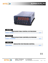
SYROS
SY24 – SY48 – SY49 – SY96 MODELS

1
SYROS
SY24 – SY48 – SY49 – SY96
Thank you for your purchasing this Digital Temperature Controller. Please check that the product is
exactly the one you ordered and use it according to the following instructions. (Please refer to a separate
operation manual for details.) Dealers are cordially requested to ensure the delivery of this Instruction
Manual to hands of the end-users.
NOTICE
The contents of this document may be changed in the future without prior notice.
We paid the utmost care for the accuracy of the contents. However, we are not liable for direct and
indirect damages resulting from incorrect descriptions, omission of information, and use of information in
this document.
INDEX
Index ...................................................................................... 1
Check Of specifications and accessories ..................................... 2
Safety precautions ................................................................... 2
Index ...................................................................................... 8
1. Installation/mounting............................................................ 9
2. Wiring ............................................................................... 12
3. Usage................................................................................ 15
4. Display and operation ......................................................... 17
5. Setting methods of temperature and parameters .................. 19
Model SY24 ....................................................................... 19
Models SY48, SY49 y SY96.................................................. 22
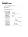
6. Functions........................................................................... 26
6-1 Control ON/OFF............................................................ 26
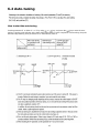
6-2 Auto-tuning ................................................................. 27
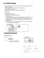
6-3 Self-tuning................................................................... 28
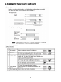
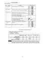
6-4 alarm function [option] ................................................. 30
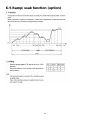
6-5 Ramp/soak function [option] ......................................... 33
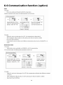
6-6 Communication function [option]................................... 34
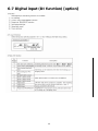
6-7 Digital input (DI function) [option]]................................ 35
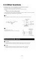
6-8 Other function ............................................................. 36
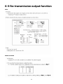
6-9 Retransmission function ................................................ 37
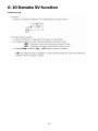
6-10 Remote SV function .................................................... 38
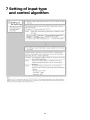
7. Setting of input type and control algorithm ........................... 39
8. Error indications ................................................................. 41
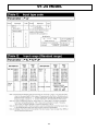
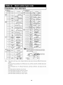
SY24 model
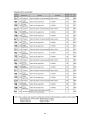
[Table 1] Input type code ....................................................... 42
[Table 2] Input Range (standard range)................................... 42
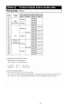
[Table 3] Alarm action type code............................................ 43
[Table 4] Control output action mode code............................... 44
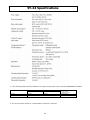
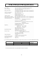
Specification .......................................................................... 45
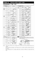
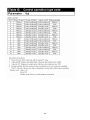
SY48, SY49 y SY96 models
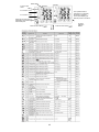
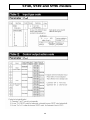
[Table 1] Input type code ....................................................... 46
[Table 2] Control output action mode code............................... 46
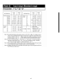
[Table 3] Input Range (standard range)................................... 47
[Table 4] Alarm action type code............................................ 48
[Table 5] Control operation type code...................................... 49
Specification .......................................................................... 50
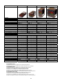
SYROS models code configuration .......................................... 51
Warranty and CE conformity ................................................... 52

2
CHECK OF SPECIFICATIONS AND ACCESSORIES
Before using the controller, check if the type and specifications are as ordered.
(A table of Model code configuration is given in Page 37).
Check that all of the following accessories are included in the package box.
Temperature controller 1 unit
Instruction manual 1 copy
Mounting mixtures 1 pc.
I/V unit (250. resistor) 1 pc. (4-20mA DC input type only)
Watertight packing 1 pc.
SAFETY PRECAUTIONS
Before using this product, the user is requested to read the following precautions carefully to ensure the
safety. Safety precautions must be taken by every user to prevent accidents.
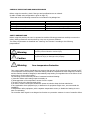
The safety requirements are classified into “Warning” and “Caution” according to the following
interpretations
:
Warning
Suggesting that the user's mishandling can
result in personal death or serious injury.
Caution
Suggesting that the user's mishandling can result
in personal injury or damage to the property.
Warning Over-temperature Protection
“Any control system design should take into account that any part of the system has the potential to fail”.
“For temperature control systems, continued heating should be considered the most dangerous condition,
and the machine should be designed to automatically stop heating if unregulated due to the failure of the
control unit or for any other reason”.
The following are the most likely causes of unwanted continued heating:
1) Controller failure with heating output constantly on
2) Disengagement of the temperature sensor from the system
3) A short circuit in the thermocouple wiring
4) A valve or switch contact point outside the system is locked to keep the heat switched on.
In any application where physical injury or destruction of equipment might occur, we recommend the
installation
of independent safety equipment, with a separate temperature sensor, to disable the heating circuit in
case of overheating.
The controller alarm signal is not designed to function as a protective measure in case of controller failure.

3
1. Warning
1.1 Installation and wiring
This controller designed to be installed at the following conditions.
Operating temperature -10 a +50 [ºC]
Operating humidity 90% RH or less (non condensation)
Installation category II
Pollution degree 2 Conforming to IEC1010-1
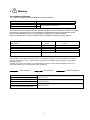
The controller must be installed such that with the exception of the connection to the mains, creepage
and clearance distances shown in the table below are maintained between the temperature probe
and any other assemblies which use or generate a voltage shown in the table below.
Failure to maintain these minimum distances would invalidate the EN 61010 safety approval.
Voltage used or generated by any
assemblies
Clearance
(mm)
Creepage
(mm)
Up to 50Vrms or Vdc 0,2 1,2
Up to 100Vrms or Vdc 0,2 1,4
Up to 150Vrms or Vdc 0,5 1,6
Up to 300Vrms or Vdc 1,5 3,0
Above de 300Vrms or Vdc
Contact with our sales office.
If the voltage shown above exceeds 50Vdc (i.e. hazardous voltage), the basic insulation is required
between all terminals of this controller and the ground, and supplementary insulation is required for
the alarm output.
Isolation class of this controller is as shown below. Be sure to check that the isolation class of the
controller satisfies your requirements before installation.
: Basic insulation : Non-insulation : Functional insulation
Mains (Power source) Measured value input, CT input, Remote SV input
Control output1 (relay output) Internal circuit
Control output2 (relay output) Control output1, 2 (SSR drive output / Current output)
Alarm outout (AL1) Re-transmission
Alarm outout (AL2) Communication (RS-485) circuit
Alarm outout (AL3) or
Heater burnout alarm output (HB) Digital input (DI).

4
• If there is a danger of a serious accident resulting from a failure or a defect in this unit, provide the unit
with an appropriate external protective circuit to prevent an accident.
• The unit is normally supplied without a power switch and fuses.
Make wiring so that the fuse is placed between the main power supply switch and this controller.
(Main power supply: 2 pole breaker, fuse rating: 250V, 1A)
• When wiring the power supply terminal, use vinyl insulated 600 volt cable or equivalent.
• To avoid the damage and failure of controller, supply the power voltage fitting to the rating.
• To avoid an electric shock and controller failure, do not turn ON the power before all wiring is completed.
• Be sure to check that the distance is kept to avoid electric shock or firing before turning the power ON.
• Keep away from terminals while the circuit is energized in order to avoid an electric shock and a
malfunction.
• Never attempt to disassemble, fabricate, modify, or repair this unit because tampering with the unit
may result in a malfunction, electric shock, or a fire.
1.2 Maintenance precautions
• Be sure to turn off the power before this controller is installed or removed in order to avoid an electric
shock, malfunction, and fault.
• Regular maintenance is recommended a longer service life of this controller.
Some parts of this controller have a limited life span, or they will be deteriorated with the lapse of time.
• One-year warranty is guaranteed for this unit including accessories, provided that the controller is
properly used.

5
2. Caution
2.1 Cautions on installation
Avoid the following places for installation.
• a place where the ambient temperature may reach beyond the range of from 0 to 50°C while in
operation.
• a place where the ambient humidity may reach beyond the range of from 45 to 85% RH while in
operation.
• a place where a change in the ambient temperature is so rapid as to cause condensation.
• a place where corrosive gases (sulfide gas and ammonia gas, in particular) or combustible gases are
emitted.
• a place where the unit is subject directly to vibration or shock.
(Vibration or shock may cause output relay malfunction.)
• a place exposed to water, oil, chemicals, steam and vapor.
(if immersed with water, take the inspection by sales office to avoid an electrical leakage and firing)
• a place where the unit is exposed to dust, salt air, or air containing iron particles.
• a place where the unit is subject to interference with static electricity, magnetism, and noise.
• a place where the unit is exposed to direct sunlight.
• a place where the heat may be accumulated due to the radiation of heat.
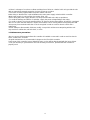
2.2 Caution on installation on panel
SY24 – SY48 MODELS
• Insert the mounting bracket (accessory) from the rear side until the main unit is securely fit into the
panel. If there should be a play, tighten two screws lightly until the play is eliminated. (Do not tighten
the screws excessively because the mounting bracket can be removed from the stopper by the force.)
Fig1 y Fig2
SY49 – SY96 MODELS
• Attach the supplied fixtures (2 pcs.) to PXR5/9 at the top and the bottom, and fasten them using a
screwdriver. The fastenin
g
torque should be approximately 0.15N·m (1.5k
g
·cm).If the plastic fixture is
fastened at excessive torque, it is split horizontally around the center,thus allowin
g
the torque to be
released. If a split appears around the center, there is no problem with the use of the instrument. (The case
is made of plastic. Therefore, be careful not to fasten them excessively). In the case of PXR9, place the
mounting fixture into the mounting hole at the center of the main body. Fig 3 y Fig 4
Junta
Frontal
Junta
Ca
j
a
Brida
Fijación
Frontal Junta

6
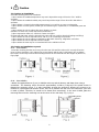
•
T
he front side of this controller conforms to NEMA 4X(equivalent with IP66). To ensure the waterproofness
between the instrument and the panel, use packings that are provided as accessories in
the following manner: (The improper fitting of packings will ruin the waterproofness.)
1 As shown in Figure 1, fit a packing to the case of the unit and then insert it in the panel.
2 Tighten screws on the fixing frame or fixtures so that no gaps are given between the front of controller
and packing and between panels. Check that there are no deviation and deformation of packing as
shown in Fig. 5.
If panel strength is weak, it may causes a gap between the packing and the panel, thus impairing
water resistance.
Standard : Vertical mounting, flush on the panel. (The controller is horizontal.)
When mounting the controller on tilted surface, the maximum tilt angle is 30°(degree) from vertical.
(Caution)
• Don’t block the openings around the controller, or radiation effect will be
reduced.
• Don’t block the ventilation openings at the top of the terminal block.
Junta
Junta
Fi
g
.5

7
2.3 Precautions in wiring connections
• For the thermocouple sensor type, use thermocouple compensation wires for wiring.
For the RTD type, use a wiring material with a small lead wire resistance and no resistance differentials
among three wires.
• Keep input lines away from power line and load line to avoid the influence from noise induced.
• For the input and output signal lines, be sure to use shielded wires and keep them away from each
other.
• If a noise level is excessive in the power supply, the additional installation of an insulating transformer
and the use of a noise filter are recommended.
(example: ZMB22R5-11 Noise Filter manufactured by TDK)
Make sure that the noise filter is installed to a place such as a panel that is properly grounded. The
wiring between the noise filter output terminal and the instrument power supply terminal should be
made as short as possible. None of fuses or switches should be installed to the wiring on the noise
filter output side because the filter effect will be degraded by such an installation.
• A better anti-noise effect can be expected by using stranded power supply cable for the instrument.
(The shorter the stranding pitch is, the better the anti-noise effect can be expected.)
• For the unit with an alarm against a failure (burn-out) in the heater, use the same power line for
connection of the power supplies for the heater and the controller.
• A setup time is required for the contact output when the power is turned on. If the contact output is
used as a signal for an external interlock circuit, use a delay relay at the same time.
• Use the auxiliary relay since the life is shortened if full capacity load is connected to the output relay.
SSR/SSC drive output type is preferred if the output operations occur frequently.
[Proportional interval] relay output: 30 seconds or more,
SSR/SSC: one second or more
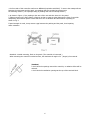
• If inductive load such as magnetic switches connected as a relay output load, it is recommended to
use Z-Trap manufactured by Fuji Electric to protect a contact from switching serge and keep a longer
life.
power supply voltage: 100 V)---> Z-trap 240V Ø 5mm
power supply voltage: 200 V ---> Z-trap 470V Ø 5mm
Where to install : Connect it between contacts of the relay control output.
Exam
p
le: Z-
T
ra
p
connection
2.4 Requirements for key operation/operation in abnormalities
• Prior to the operation, be sure to check alarm functions, since a failure in the proper setting will result
in a failure in the proper output of an alarm in case of an abnormality.
• A display of UUUU or LLLL will appear in case of a break in the input. Be sure to turn off the power
when a sensor is replaced.
2.5 Others
• Do not use organic solvents such as alcohol and benzine to wipe this controller. Use a neutral detergent
for wiping the controller.

8
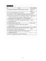
Index
< REFERENCE ITEMS> <DESCRIPTION>
Confirming type specification • Confirming that the delivered controller is
equal to the ordered one.
1. Installation/mounting • Outline dimensions
• Panel cutout dimensions
• Mounting method on the panel
2. Wiring • Terminal connection diagram
Power on
3. Usages
4. Display and operation
5 Setting method of temperature
and parameters
6. Functions
*Note
7. Setting of input type
and control algorithm.
Operation
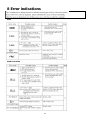
8. Error indications
(Note) *To start the operation, wait for about 30 minutes after the power-on for warm up.
• Set value change method
• Basic operation method
• List of parameters
• List of input/output/alarm codes
• Setting of input type and ranges
• Selecting of control method

9
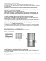
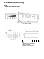
1 Installation/mounting
SY24
Number of units 2 3 4 5 6
a 93 141 189 237 285
Note:
• Watertight feature is unavailable if
mounted close together.
• Maximum ambient temperature is
45°C if mounted close together.
Controller outline dimensions (unit:mm)
Panel cutout dimensions (unit:mm)
For se
p
arated mountin
g
For mounting close together (n controllers)
Waterti
g
ht packin
g
Mountin
g
bracket
Panel thickness 1 to 8 mm

10
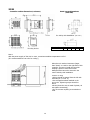
SY48
Note 1
With the power supply of 200 VAC or more, a maximum ambient temperature is 45°C.
(It is recommended to use a fan for cooling.)
When there is another instrument (larger
than 70mm) or a wall on the ri
g
ht side of this
controller, be sure to install the controller
keeping a space of more than 30mm.
Wateproofness cannot be ensured in the
case of side-by-side installation.
Cautions on wiring
• Wiring should be started from the left side
terminal (No. 1 to No. 6).
• Use crimped terminals matched to the
screw size. Tightening torque should be
about
0.8 Nm (Since the case is made of plastic, do
not tighten excessively).
• Do not connect anything to terminals not
used.
Number of units 2 3 4 5 6
a 93 141 189 237 285
Controller outline dimensions (unit:mm) Panel cutout dimensions
(unit:mm)
Junta
Brida fi
j
ación
For side by side installation. (see note 1)

11
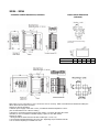
Controller outline dimensions (unit:mm)
SY49 – SY96
Panel cutout dimensions
(unit:mm)
Note) Water proof is impossible in case of horizontal close-fit mounting. Panel cutout dimensions should also satisfy the
above values after the panel is coated.
Cautions on close-fit mounting
• With the power supply of 200 VAC or more, a maximum ambient temperature is 45°C.
(It is recommended to use a fan for cooling.)
• When there is another instrument (larger than 70mm) or a wall on the right side of this
controller, be sure to install the controller keeping a space of more than 30mm.
Cautions on wiring
• Wiring should be started from the left side terminal (No. 1 to No. 12).
• Use crimped terminals matched to the screw size. Tightening torque should be 0.8 Nm.
• Do not connect an
y
thin
g
to terminals not used.
Horizontal close-fit mounting
(see note)
Number of units 2 3 4 5 6
a 93 141 189 237 285

12
2 Wiring
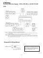
Terminal connection diagram (100 to 240 VAC) or (24 VDC/24 VAC)
SY24
Salida control 2
Relé Salida SSR/SSC 4-20 mADC
Entrada digital 1
Communication Entrada digital 2 Retransmission
Salida alarma 2
Entrada de valor medido
Corriente/Voltaje Sensor Termopar
Salida control 1
Relé Salida SSR/SSC 4-20 mADC
Salida alarma 1
A
limentación
Nota 4
Note1) Check the power supply voltage before installation.
Note2) Connect the 250 Ω resistor) (accessory) between the terminal w and e in case of current input.
Note3) Tighten the terminal screw securely with fastening torque of 0.4N·m.
Note4) When the 10th digit of the code symbol is "C", "A", or "B", connect the power according to the connection diagram of
24VAC/24VDC power supply. Input of power of 30VAC/30VDC or more will damage the instrument.
Designation of Wiring Material
CAUTION: To prevent disconnection or
short circuit, never use the wire other than
the one stated above, and make sure to
insert it toward the recess of the terminal
block. Fastening torque: 0.4N·m

13
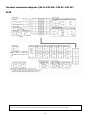
Terminal connection diagram (100 to 240 VAC, 24V AC/24V DC)
SY48
24V AC/DC 100-240V AC
En el caso de 1 punto de
entrada digital conecte el
terminal de entrada digital
entre los terminales 7 y 8
Note 1) Check the power supply voltage before installation.
Note 2) Connect the 250 Ω resistor (accessory) between the terminal 17 and 18 in case of current
In the case of 1 di
g
ital input
point connect the digital input
terminal between terminals 7 and
8

14
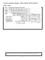
Terminal connection diagram (100 to 240 AC, 24V AC/24V DC)
SY49 – SY96
Note 1) Check the power supply voltage before installation.
Note 2) Connect the 250 Ω resistor (accessory) between the terminal 35 and 36 in case of current input.
In the case of
1 digital input
point connect
the digital
input terminal
between
terminals 1
and 2

15
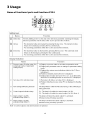
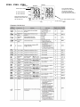
3 Usage
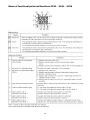
Name of functional parts and functions SY24
Nombre Función
S1 Tecla de
selección
Es la tecla que va al 1er, 2º o 3er bloque de parámetros, alternando la visualización
entre el parámetro y los datos del 1er, 2º o 3er bloque.
S2 Tecla arriba · El valor numérico aumenta si se pulsa esta tecla una vez. El valor numérico sigue
aumentado si se pulsa de forma continuada.
· Para buscar parámetros dentro del 1er, 2º o 3er bloque de parámetros.
S3 Tecla abajo · El valor numérico decrece si se pulsa esta tecla una vez. El valor numérico sigue
decreciendo si se pulsa de forma continuada.
· Para buscar parámetros dentro del 1er, 2º o 3er bloque de parámetros.
Teclas de confi
g
uración
V
isualización/Indicación
Nombre Función
1 Valor de proceso (PV)/valor de
consigna (SV) visualización
del nombre del parámetro
1) Visualiza valor de proceso o valor de consigna en modo
funcionamiento.
2) Se visualizan los símbolos del parámetro o el parámetro en el
modo de configuración de parámetros
3) Se visualizan distintas indicaciones de error (consúltese el
capítulo “8. Indicaciones de error”).
4) Parpadea en modo espera al mostrar valor SV.
5) Muestra valor (SV) y “SV-x” (x:1 a 4) alternativamente
cuando la función SV-switching es usada y se muestra SV
2 Led indicación valor de consigna
(SV)
1) Led encendido al mostrar valor (SV).
2) Parpadea mientras se muestra el valor (PV) en modo espera.
3 Indicación auto-tuning/self-tuning Parpadea mientras se realiza auto-tuning o self-tuning del PID.
4 Led indicación salida de control C1 : Encendido mientras la salida de control 1 está activa.
C2 : Encendido mientras la salida de control 2 está activa. (Nota1)
5 Salida alarma 1 (ALM1)
Led (Nota 1)
El Led se enciende al activarse la alarma 1.
Parpadea durante el funcionamiento retardado.
6 Salida alarma 2 (ALM2)
Led (Nota 1)
El Led se enciende al activarse la alarma 2.
Parpadea durante el funcionamiento retardado.
Nota 1) La salida de control 2 y la función de alarma son opcionales.

16
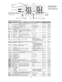
Name of functional parts and functions SY48 – SY49 – SY96
Nombre Función
S1 Tecla de
selección
Es la tecla que va al 1er, 2º o 3er bloque de parámetros, alternando la
visualización entre el parámetro y los datos del 1er, 2º o 3er bloque.
S2 Tecla arriba · El valor numérico aumenta si se pulsa esta tecla una vez. El valor
numérico sigue aumentado si se pulsa de forma continuada.
· Para buscar parámetros dentro del 1er, 2º o 3er bloque de parámetros.
S3 Tecla abajo · El valor numérico decrece si se pulsa esta tecla una vez. El valor
numérico sigue decreciendo si se pulsa de forma continuada.
· Para buscar parámetros dentro del 1er, 2º o 3er bloque de parámetros.
Teclas de confi
g
uración
V
isualización/Indicación
Nombre Función
1 Valor de proceso (PV)/visualización
del nombre del parámetro
1) Se visualiza un valor de proceso (PV).
2) Se visualizan los símbolos del parámetro en el modo de
configuración de parámetros.
3) Se visualizan distintas indicaciones de error (consúltese el
capítulo “8. Indicaciones de error”).
2 Piloto de indicación del valor de
consigna (SV)
El piloto se enciende mientras se visualiza un valor de consigna
3 Visualización del valor de consigna
(SV)/configuración de parámetros
1) Se visualiza un valor de consigna (SV).
2) Se visualizan las configuraciones del parámetro en el modo
de configuración de parámetros.
3) Parpadea en el modo de espera (stand-by).
4) Se visualiza el valor de consigna (SV ) y “SV-1”
alternativamente
cuando se utiliza la función de configuración de parámetros
5) Se visualiza el valor de consigna (SV) y “rSV”
alternativamente en el funcionamiento remoto
4 Indicación de auto-tuning/self-tuning El piloto parpadea mientras se está realizando el auto-tuning o
self-tuning del PID.
5 Piloto de indicación de salida de
control
C1: piloto encendido mientras la salida de control 1 está en ON
C2: piloto encendido mientras la salida de control 2 está en ON.
(Nota 1)
6 Piloto de indicación de salida de
alarma (AL1) (Nota 1)
El piloto está encendido mientras la alarma 1 está activada.
Parpadea durante el funcionamiento retardado (Nota 2)
7 Piloto de indicación de salida de
alarma (AL2) (Nota 1)
El piloto está encendido mientras la alarma 2 está activada.
Parpadea durante el funcionamiento retardado (Nota 2)
8 Piloto de indicación de salida de
alarma (AL23) (Nota 1)
El piloto está encendido mientras la alarma 3 está activada.
Parpadea durante el funcionamiento retardado (Nota 2)
Nota 1) La salida de control 2 y la función de alarma son opcionales.
Nota 2) El piloto no parpadea mientras el temporizador está activado.

17
SV indication lamp flickers
Showing the
process
value (PV)
Showing the
set value
(SV)
SV indication lamp is lit
The set value (SV)
Can be changed.
Press The Press The
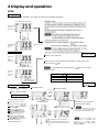
4 Display and operation
SY24
Standby mode
To perform standby operation, set "STby" as ON in the 1st block parameter.
Aviso: La visualización del SV no parpadea mientras
el 1er, 2º y 3er bloque de parámetros se están
visualizando.
Operation mode
Parameters setting mode
1 Change of set value (SV)
2 Shift to the 1st, 2nd and 3rd block parameter To shift to the other
blocks, press the key.
: Depending on the pressing time of key, you can select
the block to shift.
Pressing time Shifting block
About 1 sec pressing 1st block
About 3 sec pressing 2nd block
About 5 sec pressing 3rd block
Showing
the
set value
(SV)
SV indication lamp is lit
Showing
the
process
value (PV)
Press the for 2 seconds 1 Parameter selection
2 Parameter settings
3 Shift to operation condition
Operation mode
Press
The key
once
Parameter search
Parameter set value change
Press
The key
once
When the set value is changed
the numeric value flickers.
Increases set value
Decreases set value
If it is left in this state for 30 seconds,
the change becomes invalid, and it
returns to Operation/Standby mode.
By repeating the same procedure, the
parameters can be displayed according to the
parameter list shown in
“
5, Setting methods of …..
Parameter setting procedure:
1 Select a parameter you want
to set by pressing the or
key
2-1 Press the key to display the
parameter set value.
2-2 Press the or key to
change the parameter set value.
2-3 After the parameter has been
changed, press the key for
registration.
3 To shift to Operation/Standby
press the key for 2 seconds
4 If unoperated state continues for
30 seconds, it returns to
Operation/Standby mode.
Switching by 1st
block STby settings
Switching by
the ke
y
After the parameter has
been changed, if unoperated state
continues for 30 seconds without
pressing the key, setting change
becomes invalid
Registers parameter set value,
returning to the parameter shift mode 1

18
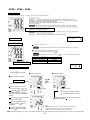
Press ThePress The
Press
t
he
once
SY48 – SY49 – SY96
Standby mode
To perform standby operation, set "STby" as ON in the 1st block parameter.
Switching by 1st block
STby settings
When the SV lamp is lit, the set value
(SV) is displayed at the lower line.
The set value (SV) can be changed.
Parameters setting mode
Press the for 2 seconds
Note: If the upper display (PV) comes off (or kept distinguished), make the setting once again by adding 64 to the set value of parameter DP13.
1 Parameter selection 2 Parameter settings
Parameter search Parameter change
Increases parameter set value
Decreases parameter set value
Register parameter set value, returning to the
parameter shift mode 1
By repeating the same procedure, the parameters can be
displayed according to the parameter list shown in "5.
Setting methods of temperature and parameters."
Operation mode
3 Shift to operation condition
Parameter setting procedure:
1 Select a parameter you want
to set by pressing the or
2-1 Press the key to allow the
parameter to change (under the
changing conditions, the parameter
flickers).
2-2 Press the or key to change
the parameter set value.
2-3 After the parameter has been
changed, press the key for
registration.
3 To shift to Operation/Standby
press the key for 2 seconds
Switching by
the key
1 Change of set value (SV)
After the data setting, the data are registered automatically in 3 seconds.
2 Shift to the 1st, 2nd and 3rd block parameter
To shift to the other blocks, press the key
Depending on the pressing time of key, you can select the block to shift.
Pressing time Shifting block
About 1 sec pressing 1st block
About 3 sec pressing 2nd block
About 5 sec pressing 3rd block
Operation mode

19
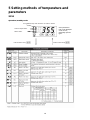
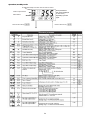
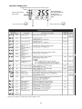
5 Setting methods of temperature and
parameters
SY24
Operation/standby mode
Some parameters
may not be displayed
on the screen,
depending upon the
types.
1er bloque de parámetros
Símbolo de visualización
de parámetros Parámetro Descripción valores
defecto Remarks
STbY Configuración de espera Alterna entre RUN o Standby en el control.
ON: Control standby (Salida: OFF, alarma: OFF)
OFF: Control RUN OFF
ProG Control rampa/mantenimiento OFF: parada, rUn: marcha, HLd: mantenimiento OFF
LACH Cancelar latch de alarma 1: Libera el latch de alarma. 0
AT Auto-tuning 0: OFF, 1: Standard AT start, 2: Low PV type AT
start 0
TM-1 Visualización temporizador 1 10
TM-2 Visualización temporizador 2
Visualización del temporizador que indica el
tiempo restante 10
AL1 Valor de consigna de alarma 1 (Aparece cuando el tipo de alarma es de 1 a 10).
Rango configuración: Nota 1 10 Tabla 3
(Nota 1)
A1-L Valor de consigna de límite
inferior alarma 1 10 Tabla 3
(Nota 1)
A1-H Valor de consigna de límite
superior alarma 1
(Aparece cuando el tipo de alarma es de 16 a 31)
Rango configuración: Nota 1 10 Tabla 3
(Nota 1)
AL2 Valor de consigna de alarma 2 (Aparece cuando el tipo de alarma es de 1 a 10).
Rango configuración: Nota 1 10 Tabla 3
(Nota 1)
A2-L Valor de consigna de límite
inferior alarma 2 10 Tabla 3
(Nota 1)
A2-H Valor de consigna de límite
superior alarma 2
(Aparece cuando el tipo de alarma es de 16 a 31)
Rango configuración: Nota 1 10 Tabla 3
(Nota 1)
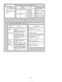
LoC Key lock
Ajuste del estado de bloqueo del teclado.
Todos parámetros SV
tecla Comunicación Tecla Comunicación
0 O O O O
1 X O X O
2 X O O O
3 O X O X
4 X X X X
5 X X O X
O Ajuste activado, X: ajuste desactivado
0
Nota 1) Rango de ajuste : 0 a 100%FS (en caso de valor absolute de alarma)
–100 to 100%FS (en caso de alarma de desviación)
Nota 2) No ajustar nunca "TC" / "TC2" = 0
Press for about 1s key
SV indication lamp is lit when the set value is shown.
Control output status
Alarm status
Press for about 2s key
Page is loading ...
Page is loading ...
Page is loading ...
Page is loading ...
Page is loading ...
Page is loading ...
Page is loading ...
Page is loading ...
Page is loading ...
Page is loading ...
Page is loading ...
Page is loading ...
Page is loading ...
Page is loading ...
Page is loading ...
Page is loading ...
Page is loading ...
Page is loading ...
Page is loading ...
Page is loading ...
Page is loading ...
Page is loading ...
Page is loading ...
Page is loading ...
Page is loading ...
Page is loading ...
Page is loading ...
Page is loading ...
Page is loading ...
Page is loading ...
Page is loading ...
Page is loading ...
Page is loading ...
Page is loading ...
Page is loading ...
Page is loading ...
-
 1
1
-
 2
2
-
 3
3
-
 4
4
-
 5
5
-
 6
6
-
 7
7
-
 8
8
-
 9
9
-
 10
10
-
 11
11
-
 12
12
-
 13
13
-
 14
14
-
 15
15
-
 16
16
-
 17
17
-
 18
18
-
 19
19
-
 20
20
-
 21
21
-
 22
22
-
 23
23
-
 24
24
-
 25
25
-
 26
26
-
 27
27
-
 28
28
-
 29
29
-
 30
30
-
 31
31
-
 32
32
-
 33
33
-
 34
34
-
 35
35
-
 36
36
-
 37
37
-
 38
38
-
 39
39
-
 40
40
-
 41
41
-
 42
42
-
 43
43
-
 44
44
-
 45
45
-
 46
46
-
 47
47
-
 48
48
-
 49
49
-
 50
50
-
 51
51
-
 52
52
-
 53
53
-
 54
54
-
 55
55
-
 56
56


Ditel SY Technical Manual
- Type
- Technical Manual
- This manual is also suitable for
Ask a question and I''ll find the answer in the document
Finding information in a document is now easier with AI
in other languages
- español: Ditel SY
Related papers


Other documents
-
Eurotherm 3200 User guide
-
Carel humiSteam Basic UE009 User manual
-
-
-
-
WineMate 3500HZD User manual
-
-
Carel ir33+ Quick start guide
-
-