Solt GGSAP2560W User manual
- Category
- Mobile air conditioners
- Type
- User manual

E S S E N T I A L S FOR LIFE
User
Manual
MODEL
GGSAP2560W
Portable
Air-conditioner
2.56kW

2
For future reference, please record the following information which can be found on the rating plate
and the date of purchase which can be found on your sales invoice.
STORE DETAILS
STORE NAME
|
ADDRESS
|
TELEPHONE
|
PURCHASE DATE
|
PRODUCT DETAILS
MODEL NO.
|
SERIAL NO.*
|
Purchase Details

3
Welcome Congratulations on purchasing
your new Portable Air-conditioner!
The Sôlt brand is proudly
distributed within Australia
by Residentia Group Pty Ltd.
Please refer to the warranty card at the rear of this manual
for information regarding your product’s parts and labour
warranty, or visit us online at www.residentia.group
At Residentia Group, we are customer obsessed and our
Support Team are there to ensure you get the most out of
your appliance. Should you want to learn more about your
rangehood features, and importantly taking care of your
appliance when cleaning, our Support Team are here
to help.
You can use our online Support Centre at anytime by
visiting http://support.residentiagroup.com.au, or you can
contact us via calling us on 1300 11 HELP (4357).
It is important that you read through the following use and
care manual thoroughly to familiarise yourself with the
installation and operation requirements of your appliance
to ensure optimum performance.
Again, thank you for choosing an Sôlt appliance and we
look forward to being of service to you.
Kind Regards,
The Residentia Team
Residentia Group
—
Head Office.
165 Barkly Ave
Burnley
Victoria 3121
Australia
—
ACN.
600 546 656
—
Online.
residentia.group

4
This page
is intentionally
left blank

Contents 2 Purchase Details
3 Welcome
6 General Safety Instructions
12 Your Portable Air-conditioner
14 Installation
16 Getting Started
18 Operation Instructions
21 FAQs & Troubleshooting Guide
22 Other Useful Information
24 Technical Specifications
25 Attach Your Receipt
26 Warranty Information
Sôlt recommends the use of original spare parts. When contacting our customer service team, please ensure
that you have the following information at hand (which can be found on your appliances’ rating plate).
— Model Number
— Serial Number
T . 1300 11 4357 | E. support@residentiagroup.com.au
Customer Care

6
READ CAREFULLY AND KEEP FOR FUTURE REFERENCE
Read this manual thoroughly before first use, even if
you are familiar with this type of product. The safety
precautions enclosed herein reduce the risk of fire, electric
shock and injury when correctly adhered to. Make sure
you understand all instructions and warnings.
Keep the manual in a safe place for future reference,
along with the completed warranty card and purchase
receipt. If you sell or transfer ownership of this product,
pass on these instructions to the new owner.
Always follow basic safety precautions and accident
prevention measures when using an electrical appliance,
including the following:
ELECTRICAL SAFETY AND CORD HANDLING
–Voltage: Before turning on the air conditioner, ensure
the electrical voltage and circuit frequency correspond
to those indicated on the appliance.
–Socket: Ensure your electrical outlet is properly
installed and earthed and complies with your local
electrical safety requirements.
–Moisture: To reduce the risk of electrocution, never
operate the appliance with wet hands; never
submerge it in water or spill liquids into it. Do not use it
in a bathroom or laundry, or where it can be splashed
with water.
–Power supply cord: Do not kink or damage the
cord. Do not pull the cord or place it near a heat
source. Always unwind the cord completely to avoid
overheating. Run the cord in such a way so that no
one will trip over it.
–Extension cord/adaptor: Do not use this appliance
with an extension cord or power adaptor.
–Damaged cord: If the supply cord is damaged, do
not use the appliance. A damaged power supply cord
must be replaced by the manufacturer or its service
agent or a similarly qualified person in order to avoid
a hazard. Contact our after sales support centre.
–WARNING: Do not use when damaged! In case of
damage, switch off the appliance, unplug it and
contact our after sales support centre. Do not pick
up or operate a damaged appliance, or after it
malfunctions or has been dropped or damaged in
any manner.
–Power button: Always use the on/off button on the
control panel to turn the product on or off. Never
simply switch the product on or off by plugging it into
or unplugging it from the wall socket.
–Disconnect: Turn off the unit first and then unplug
it when it is not in use and before maintenance or
cleaning, but do not unplug it when it is in operation,
as this could create a spark and cause a fire. Grip by
the plug, do not pull by the cord when disconnecting.
–RCD: The installation of a residual current device
(safety switch) is recommended to provide additional
safety protection when using electrical appliances. It
is advisable that a safety switch with a rated residual
operating current not exceeding 30mA be installed in
the electrical circuit supplying the appliance. See your
electrician for professional advice.
– Never try to open the housing, modify or alter the
product in any way.
USAGE CONDITIONS AND RESTRICTIONS
–Intended use: This appliance is intended for air
conditioning domestic environments. It is not suitable
for commercial, industrial or trade use. Do not use it
for any other purpose (such as cooling food, etc.) and
only use it as described in this manual.
–Common sense: These instructions are not intended to
cover every possible condition and situation. As with
any electrical appliance, common sense and caution
are therefore always recommended when installing,
operating and maintaining the unit.
–No outdoor use: Do not use the unit outdoors.
It is for indoor use only.
–Usage restriction: This appliance is not intended
for use by persons (including children) with reduced
physical, sensory or mental capabilities, or lack of
experience and knowledge, unless they have been
given supervision or instruction concerning use of
the appliance in a safe way and understand the
hazards involved.
–No external timer: This appliance is not intended to
be used with an external timer or a separate remote
control system.
–WARNING: Do not cover! Do not cover the air
conditioner or obstruct any air inlet or outlet grilles.
Obstructing these openings causes a fire hazard,
reduces the operating efficiency and may lead to
malfunction or damage.
–Air outlets: Do not insert any objects, or your fingers,
into the air outlet, and make sure to warn children of
the dangers.
–Children: Supervise children to ensure they do not
play with the appliance. Close supervision is necessary
when any appliance is used by or near children.
Cleaning and user maintenance shall not be made by
children without supervision.
General Safety Instructions

7
–Unattended: Do not leave the appliance unattended
when in use.
–Attachments: The use of attachments not
recommended or sold by the manufacturer may cause
fire, electric shock or injury.
–Startup settings: Set the unit to maximum cooling
and high speed ventilation for the initial startup, then
adjust the unit down to a more comfortable setting
as required.
–Airflow: Do not direct the airflow onto plants or
animals, as long and direct exposure to cold air from
the air conditioner could adversely affect them.
–Cold air exposure: Never remain directly exposed
to the flow of cold air for a long time, as direct
and prolonged exposure to cold air from the air
conditioner could be dangerous for your health. Take
particular care in rooms where there are children, old,
or sick people.
–Moving the appliance: When moving the air
conditioner, always turn off and disconnect the power
supply, and move it slowly.
– Never place any objects containing liquid, such as
flower vases or drinks, on top of the product.
– Never handle the product with wet hands or
while barefoot.
– Switch off and unplug the product when it is not in use.
–WARNING! If the product should tip over, immediately
turn it off and unplug it.
CLEANING AND MAINTENANCE
–Disconnect: Make sure the appliance is disconnected
from the power supply when it will not be used for a
long time and before carrying out any cleaning
or maintenance.
–Air filter: Keep the air filter clean. Do not use the unit
without the air filters fitted. Using it without air filters
could cause an excessive accumulation of dust or
waste on the inner parts of the device with possible
subsequent failures.
–Service and repair: The air conditioner has no
user-serviceable parts contained inside. Do not
attempt to disassemble, modify or conduct repairs on
this unit. It has been built in accordance with relevant
safety and performance standards. An electrical
specialist must carry out all repairs. Contact our after
sales support line for advice on service.
–Cooling efficiency: To help cooling efficiency, keep
blinds and curtains closed during the sunniest part of
the day. Close off any fireplace damper, floor and/or
wall register so cool air does not escape through the
chimney or duct work.
INSTALLATION
–Proper installation: Install the appliance according
to the instructions in this manual and national wiring
regulations. Improper installation may result in the
risk of fire, electric shock and/or injury. We assume no
responsibility for any eventual damages caused by
improper installation or faulty use.
–Upright position: Place the unit on a flat surface to
reduce the risk of it tipping over. Do not tilt the unit,
always keep it upright. If the unit has not been kept
upright (such as during storage), wait for at least
24 hours before operation.
–Obstructions: Do not locate the air conditioner where
furniture or other objects can obstruct the airflow.
–Do not cover: Do not cover the air conditioner or
obstruct any air inlet or outlet grilles. Obstructing
these openings causes a fire hazard, reduces the
operating efficiency and may lead to malfunction or
damage.
–Chemicals: Do not install the air conditioner in
environments where the air could contain gas, oil
or sulphur. Do not let chemical substances come
into contact with the unit. Do not use the unit in the
presence of flammable substances or vapour such as
alcohol, insecticides, petrol etc.
–Heat: Do not install the air conditioner near sources
of heat, or exposed to direct sunlight.
–Room size: The unit is designed for use in a room
of 12–18m² size.
–Clearances: Always keep a clearance of at least
30cm from walls, furniture and curtains.
This symbol shows that this appliance uses a flammable refrigerant
(R290). If the refrigerant is leaked and exposed to an external ignition
source, there is a risk of fire.

8
General Safety Instructions (Continued)
WARNING FOR USING R32R290 REFRIGERANT
– Do not use means to accelerate the defrosting
process or to clean, other than those recommended
by the manufacturer.
– The appliance shall be stored in a room without
continuously operating ignition sources (for example:
open flames, an operating gas appliance or an
operating electric heater).
– Do not pierce or burn.
– Be aware that the refrigerants may not contain
an odour.
– Appliance should be installed, operated and stored
in a room with a floor area according to the amount
of refrigerant to be charged. For specific information
on the type of gas and the amount, please refer to
the relevant label on the unit itself. When there are
differences between the label and the manual on the
Min. room area description, the description on label
shall prevail.
For R290:
Amount of refrigerant (kg) Min. room area (m²)
> 0.0836 and ≤ 0.1045 5
> 0.1045 and ≤ 0.1254 6
> 0.1254 and ≤ 0.1463 7
> 0.1463 and ≤ 0.1672 8
> 0.1672 and ≤ 0.1881 9
> 0.1881 and ≤ 0.2090 10
> 0.2090 and ≤ 0.2299 11
> 0.2299 and ≤ 0.2508 12
> 0.2508 and ≤ 0.2717 13
> 0.2717 and ≤ 0.2926 14
> 0.2926 and ≤ 0.3135 15
– Compliance with national gas regulations shall be
observed.
– Keep ventilation openings clear of obstruction.
– The appliance shall be stored so as to prevent
mechanical damage from occurring.
– A warning that the appliance shall be stored in a
well-ventilated area where the room size corresponds
to the room area as specified for operation.
– Any person who is involved with working on or
breaking into a refrigerant circuit should hold
a current valid certificate from an industry-
accredited assessment authority, which authorises
their competence to handle refrigerants safely in
accordance with an industry recognised
assessment specification.
– Servicing shall only be performed as recommended by
the equipment manufacturer. Maintenance and repair
requiring the assistance of other skilled personnel shall
be carried out under the supervision of the person
competent in the use of flammable refrigerants.
– The appliance shall be stored in a room without
continuously operating open flames (for example an
operating gas appliance) and ignition sources (for
example an operating electric heater).
Explanation of symbols displayed on the unit
(For the unit adopts R32/R290 Refrigerant only):
Safety
Precautions
Page 6
WARNING for Using R32/R290 Refrigerant
Do not use means to accelerate the defrosting process or to clean, other than those recommended by
the manufacturer.
The appliance shall be stored in a room without continuously operating ignition sources (for example:
open flames, an operating gas appliance or an operating electric heater).
Do not pierce or burn.
Be aware that the refrigerants may not contain an odour.
Compliance with national gas regulations shall be observed.
Keep ventilation openings clear of obstruction.
The appliance shall be stored so as to prevent mechanical damage from occurring.
A warning that the appliance shall be stored in a well-ventilated area where the room size corresponds
to the room area as specified for operation.
Any person who is involved with working on or breaking into a refrigerant circuit should hold a current
valid certificate from an industry-accredited assessment authority, which authorises their competence
to handle refrigerants safely in accordance with an industry recognised assessment specification.
Servicing shall only be performed as recommended by the equipment manufacturer. Maintenance
and repair requiring the assistance of other skilled personnel shall be carried out under the supervision
of the person competent in the use of flammable refrigerants.
The appliance shall be stored in a room without continuously operating open flames (for example an
operating gas appliance) and ignition sources (for example an operating electric heater).
Appliance should be installed, operated and stored in a room with a floor area according to the amount
of refrigerant to be chargedFor specific information on the type of gas and the amount, please refer
to the relevant label on the unit itself.
Appliance should be installed, operated and stored in a room with a floor area larger than 4 m .
Caution: Risk of fire/
flammable materials
Explanation of symbols displayed on the unit(For the
unit adopts R32/R290 Refrigerant only):
WARNING
CAUTION
CAUTION
CAUTION
This symbol shows that this appliance used a
flammable refrigerant. If the refrigerant is leaked and
exposed to an external ignition source, there is a risk
of fire.
This symbol shows that the operation manual
should be read carefully.
This symbol shows that a service personnel should be
handling this equipment with reference to the
installation manual.
This symbol shows that information is available such
as the operating manual or installation manual.
2
WARNING This symbol shows that this appliance
used a flammable refrigerant. If the
refrigerant is leaked and exposed to
an external ignition source, there is a
risk of fire.
Safety
Precautions
Page 6
WARNING for Using R32/R290 Refrigerant
Do not use means to accelerate the defrosting process or to clean, other than those recommended by
the manufacturer.
The appliance shall be stored in a room without continuously operating ignition sources (for example:
open flames, an operating gas appliance or an operating electric heater).
Do not pierce or burn.
Be aware that the refrigerants may not contain an odour.
Compliance with national gas regulations shall be observed.
Keep ventilation openings clear of obstruction.
The appliance shall be stored so as to prevent mechanical damage from occurring.
A warning that the appliance shall be stored in a well-ventilated area where the room size corresponds
to the room area as specified for operation.
Any person who is involved with working on or breaking into a refrigerant circuit should hold a current
valid certificate from an industry-accredited assessment authority, which authorises their competence
to handle refrigerants safely in accordance with an industry recognised assessment specification.
Servicing shall only be performed as recommended by the equipment manufacturer. Maintenance
and repair requiring the assistance of other skilled personnel shall be carried out under the supervision
of the person competent in the use of flammable refrigerants.
The appliance shall be stored in a room without continuously operating open flames (for example an
operating gas appliance) and ignition sources (for example an operating electric heater).
Appliance should be installed, operated and stored in a room with a floor area according to the amount
of refrigerant to be chargedFor specific information on the type of gas and the amount, please refer
to the relevant label on the unit itself.
Appliance should be installed, operated and stored in a room with a floor area larger than 4 m .
Caution: Risk of fire/
flammable materials
Explanation of symbols displayed on the unit(For the
unit adopts R32/R290 Refrigerant only):
WARNING
CAUTION
CAUTION
CAUTION
This symbol shows that this appliance used a
flammable refrigerant. If the refrigerant is leaked and
exposed to an external ignition source, there is a risk
of fire.
This symbol shows that the operation manual
should be read carefully.
This symbol shows that a service personnel should be
handling this equipment with reference to the
installation manual.
This symbol shows that information is available such
as the operating manual or installation manual.
2
CAUTION This symbol shows that the operation
manual should be read carefully.
Safety
Precautions
Page 6
WARNING for Using R32/R290 Refrigerant
Do not use means to accelerate the defrosting process or to clean, other than those recommended by
the manufacturer.
The appliance shall be stored in a room without continuously operating ignition sources (for example:
open flames, an operating gas appliance or an operating electric heater).
Do not pierce or burn.
Be aware that the refrigerants may not contain an odour.
Compliance with national gas regulations shall be observed.
Keep ventilation openings clear of obstruction.
The appliance shall be stored so as to prevent mechanical damage from occurring.
A warning that the appliance shall be stored in a well-ventilated area where the room size corresponds
to the room area as specified for operation.
Any person who is involved with working on or breaking into a refrigerant circuit should hold a current
valid certificate from an industry-accredited assessment authority, which authorises their competence
to handle refrigerants safely in accordance with an industry recognised assessment specification.
Servicing shall only be performed as recommended by the equipment manufacturer. Maintenance
and repair requiring the assistance of other skilled personnel shall be carried out under the supervision
of the person competent in the use of flammable refrigerants.
The appliance shall be stored in a room without continuously operating open flames (for example an
operating gas appliance) and ignition sources (for example an operating electric heater).
Appliance should be installed, operated and stored in a room with a floor area according to the amount
of refrigerant to be chargedFor specific information on the type of gas and the amount, please refer
to the relevant label on the unit itself.
Appliance should be installed, operated and stored in a room with a floor area larger than 4 m .
Caution: Risk of fire/
flammable materials
Explanation of symbols displayed on the unit(For the
unit adopts R32/R290 Refrigerant only):
WARNING
CAUTION
CAUTION
CAUTION
This symbol shows that this appliance used a
flammable refrigerant. If the refrigerant is leaked and
exposed to an external ignition source, there is a risk
of fire.
This symbol shows that the operation manual
should be read carefully.
This symbol shows that a service personnel should be
handling this equipment with reference to the
installation manual.
This symbol shows that information is available such
as the operating manual or installation manual.
2
CAUTION This symbol shows that a service
personnel should be handling this
equipment with reference to the
installation manual.
Safety
Precautions
Page 6
WARNING for Using R32/R290 Refrigerant
Do not use means to accelerate the defrosting process or to clean, other than those recommended by
the manufacturer.
The appliance shall be stored in a room without continuously operating ignition sources (for example:
open flames, an operating gas appliance or an operating electric heater).
Do not pierce or burn.
Be aware that the refrigerants may not contain an odour.
Compliance with national gas regulations shall be observed.
Keep ventilation openings clear of obstruction.
The appliance shall be stored so as to prevent mechanical damage from occurring.
A warning that the appliance shall be stored in a well-ventilated area where the room size corresponds
to the room area as specified for operation.
Any person who is involved with working on or breaking into a refrigerant circuit should hold a current
valid certificate from an industry-accredited assessment authority, which authorises their competence
to handle refrigerants safely in accordance with an industry recognised assessment specification.
Servicing shall only be performed as recommended by the equipment manufacturer. Maintenance
and repair requiring the assistance of other skilled personnel shall be carried out under the supervision
of the person competent in the use of flammable refrigerants.
The appliance shall be stored in a room without continuously operating open flames (for example an
operating gas appliance) and ignition sources (for example an operating electric heater).
Appliance should be installed, operated and stored in a room with a floor area according to the amount
of refrigerant to be chargedFor specific information on the type of gas and the amount, please refer
to the relevant label on the unit itself.
Appliance should be installed, operated and stored in a room with a floor area larger than 4 m .
Caution: Risk of fire/
flammable materials
Explanation of symbols displayed on the unit(For the
unit adopts R32/R290 Refrigerant only):
WARNING
CAUTION
CAUTION
CAUTION
This symbol shows that this appliance used a
flammable refrigerant. If the refrigerant is leaked and
exposed to an external ignition source, there is a risk
of fire.
This symbol shows that the operation manual
should be read carefully.
This symbol shows that a service personnel should be
handling this equipment with reference to the
installation manual.
This symbol shows that information is available such
as the operating manual or installation manual.
2
CAUTION This symbol shows that information
is available such as the operating
manual or installation manual
Caution: Risk of fire /
flammable materials

9
Transport of equipment containing flammable refrigerants
See transport regulations
Marking of equipment using signs
See local regulations
Disposal of equipment using flammable refrigerants
See national regulations.
Storage of equipment/appliances
The storage of equipment should be in accordance with
the manufacturer’s instructions.
Storage of packed (unsold) equipment
Storage package protection should be constructed such
that mechanical damage to the equipment inside the
package will not cause a leak of the refrigerant charge.
The maximum number of pieces of equipment permitted
to be stored together will be determined by local
regulations.
Information on servicing
1. Checks to the area
Prior to beginning work on systems containing flammable
refrigerants, safety checks are necessary to ensure
that the risk of ignition is minimised. For repair to the
refrigerating system, the following precautions shall be
complied with prior to conducting work on the system.
2. Work procedure
Work shall be undertaken under a controlled
procedure so as to minimise the risk of a flammable
gas or vapour being present while the work is being
performed.
3. General work area
All maintenance staff and others working in the local
area shall be instructed on the nature of work being
carried out. Work in confined spaces shall be avoided.
The area around the workspace shall be sectioned off.
Ensure that the conditions within the area have been
made safe by control of flammable material.
4. Checking for presence of refrigerant
The area shall be checked with an appropriate
refrigerant detector prior to and during work, to ensure
the technician is aware of potentially flammable
atmospheres. Ensure that the leak detection
equipment being used is suitable for use with
flammable refrigerants, i.e. non-sparking, adequately
sealed or intrinsically safe.
5. Presence of fire extinguisher
If any hot work is to be conducted on the refrigeration
equipment or any associated parts, appropriate fire
extinguishing equipment shall be available to hand.
Have a dry powder or CO2 fire extinguisher adjacent
to the charging area.
6. No ignition sources
No person carrying out work in relation to a
refrigeration system which involves exposing any
pipe work that contains or has contained flammable
refrigerant shall use any sources of ignition in such a
manner that it may lead to the risk of fire or explosion.
All possible ignition sources, including cigarette
smoking, should be kept sufficiently far away from the
site of installation, repairing, removing and disposal,
during which flammable refrigerant can possibly
be released to the surrounding space. Prior to work
taking place, the area around the equipment is to be
surveyed to make sure that there are no flammable
hazards or ignition risks. No Smoking signs shall be
displayed.
7. Ventilated area
Ensure that the area is in the open or that it is
adequately ventilated before breaking into the system
or conducting any hot work. A degree of ventilation
shall continue during the period that the work is
carried out. The ventilation should safely disperse any
released refrigerant and preferably expel it externally
into the atmosphere.
8. Checks to the refrigeration equipment
Where electrical components are being changed,
they shall be fit for the purpose and to the correct
specification. At all times the manufacturer’s
maintenance and service guidelines shall be followed.
If in doubt consult the manufacturer’s technical
department for assistance. The following checks
shall be applied to installations using flammable
refrigerants:
The charge size is in accordance with the room size
within which the refrigerant containing parts are
installed;
The ventilation machinery and outlets are operating
adequately and are not obstructed;
If an indirect refrigerating circuit is being used, the
secondary circuit shall be checked for the presence
of refrigerant; Marking to the equipment continues
to be visible and legible. Markings and signs that are
illegible shall be corrected;
Refrigeration pipe or components are installed in a
position where they are unlikely to be exposed to any
substance which may corrode refrigerant containing
components, unless the components are constructed
of materials which are inherently resistant to being
corroded or are suitably protected against being
so corroded.

10
Information on servicing (Continued)
9. Checks to electrical devices
Repair and maintenance to electrical components shall
include initial safety checks and component inspection
procedures. If a fault exists that could compromise
safety, then no electrical supply shall be connected to
the circuit until it is satisfactorily dealt with. If the fault
cannot be corrected immediately but it is necessary to
continue operation, an adequate temporary solution
shall be used. This shall be reported to the owner of the
equipment so all parties are advised.
Initial safety checks shall include:
That capacitors are discharged: this shall be done in a
safe manner to avoid possibility of sparking;
That there no live electrical components and wiring
are exposed while charging, recovering or purging the
system; That there is continuity of earth bonding.
10. Repairs to sealed components
• During repairs to sealed components, all electrical
supplies shall be disconnected from the equipment
being worked upon prior to any removal of sealed
covers, etc. If it is absolutely necessary to have an
electrical supply to equipment during servicing, then
a permanently operating form of leak detection shall
be located at the most critical point to warn of a
potentially hazardous situation.
• Particular attention shall be paid to the following to
ensure that by working on electrical components, the
casing is not altered in such a way that the level of
protection is affected. This shall include damage to
cables, excessive number of connections, terminals
not made to original specification, damage to seals,
incorrect fitting of glands, etc. Ensure that apparatus
is mounted securely. Ensure that seals or sealing
materials have not degraded such that they no
longer serve the purpose of preventing the ingress of
flammable atmospheres. Replacement parts shall be in
accordance with the manufacturer’s specifications.
NOTE: The use of silicon sealant may inhibit the
effectiveness of some types of leak detection
equipment. Intrinsically safe components do not have
to be isolated prior to working on them.
11. Repair to intrinsically safe components
Do not apply any permanent inductive or capacitance
loads to the circuit without ensuring that this will
not exceed the permissible voltage and current
permitted for the equipment in use. Intrinsically safe
components are the only types that can be worked on
while live in the presence of a flammable atmosphere.
The test apparatus shall be at the correct rating.
Replace components only with parts specified by the
manufacturer. Other parts may result in the ignition of
refrigerant in the atmosphere from a leak.
12. Cabling
Check that cabling will not be subject to wear, corrosion,
excessive pressure, vibration, sharp edges or any other
adverse environmental effects. The check shall also take
into account the effects of aging or continual vibration
from sources such as compressors or fans.
13. Detection of flammable refrigerants
Under no circumstances shall potential sources of
ignition be used in the searching for or detection of
refrigerant leaks. A halide torch (or any other detector
using a naked flame) shall not be used.
14. Leak detection methods
The following leak detection methods are deemed
acceptable for systems containing flammable
refrigerants. Electronic leak detectors shall be used
to detect flammable refrigerants, but the sensitivity
may not be adequate, or may need re-calibration.
(Detection equipment shall be calibrated in a
refrigerant-free area.) Ensure that the detector is not
a potential source of ignition and is suitable for the
refrigerant used. Leak detection equipment shall be
set at a percentage of the LFL of the refrigerant and
shall be calibrated to the refrigerant employed and
the appropriate percentage of gas (25 % maximum)
is confirmed. Leak detection fluids are suitable for
use with most refrigerants but the use of detergents
containing chlorine shall be avoided as the chlorine
may react with the refrigerant and corrode the copper
pipe-work. If a leak is suspected, all naked flames shall
be removed/ extinguished. If a leakage of refrigerant
is found which requires brazing, all of the refrigerant
shall be recovered from the system, or isolated (by
means of shut off valves) in a part of the system
remote from the leak. Oxygen free nitrogen (OFN) shall
then be purged through the system both before and
during the brazing process.
15. Removal and evacuation
When breaking into the refrigerant circuit to make
repairs or for any other purpose conventional
procedures shall be used. However, it is important
that best practice is followed since flammability is
a consideration. The following procedure shall be
adhered to:
Remove refrigerant; Purge the circuit with inert gas;
Evacuate; Purge again with inert gas; Open the circuit
by cutting or brazing.
The refrigerant charge shall be recovered into the
correct recovery cylinders. The system shall be flushed
with OFN to render the unit safe. This process may
need to be repeated several times. Compressed air or
oxygen shall not be used for this task. Flushing shall be
achieved by breaking the vacuum in the system with
OFN and continuing to fill until the working pressure is
achieved, then venting to atmosphere, and
General Safety Instructions (Continued)

11
finally pulling down to a vacuum. This process shall be
repeated until no refrigerant is within the system.
When the final OFN charge is used, the system shall be
vented down to atmospheric pressure to enable work to
take place. This operation is absolutely vital if brazing
operations on the pipe-work are to take place. Ensure
that the outlet for the vacuum pump is not close to any
ignition sources and there is ventilation available.
16. Charging procedures
In addition to conventional charging procedures, the
following requirements shall be followed. Ensure that
contamination of different refrigerants does not occur
when using charging equipment. Hoses or lines shall
be as short as possible to minimise the amount of
refrigerant contained in them.
Cylinders shall be kept upright.
Ensure that the refrigeration system is earthed prior to
charging the system with refrigerant.
Label the system when charging is complete
(if not already).
Extreme care shall be taken not to overfill the
refrigeration system. Prior to recharging the system
it shall be pressure tested with OFN. The system shall
be leak tested on completion of charging but prior to
commissioning. A follow up leak test shall be carried
out prior to leaving the site.
17. Decommissioning
Before carrying out this procedure, it is essential
that the technician is completely familiar with the
equipment and all its detail. It is recommended good
practice that all refrigerants are recovered safely.
Prior to the task being carried out, an oil and
refrigerant sample shall be taken in case analysis is
required prior to re-use of reclaimed refrigerant. It is
essential that electrical power is available before the
task is commenced.
a. Become familiar with the equipment and its operation.
b. Isolate system electrically.
c. Before attempting the procedure ensure that:
Mechanical handling equipment is available, if
required, for handling refrigerant cylinders;All
personal protective equipment is available and being
used correctly; The recovery process is supervised at
all times by a competent person; Recovery equipment
and cylinders conform to the appropriate standards.
d. Pump down refrigerant system, if possible.
e. If a vacuum is not possible, make a manifold so that
refrigerant can be removed from various parts of
the system.
f. Make sure that cylinder is situated on the scales before
recovery takes place.
g. Start the recovery machine and operate in accordance
with manufacturer’s instructions.
h. Do not overfill cylinders. (No more than 80 % volume
liquid charge).
i. Do not exceed the maximum working pressure of the
cylinder, even temporarily.
j. When the cylinders have been filled correctly and the
process completed, make sure that the cylinders and
the equipment are removed from site promptly and all
isolation valves on the equipment are closed off.
k. Recovered refrigerant shall not be charged into
another refrigeration system unless it has been
cleaned and checked.
18. Labelling
Equipment shall be labelled stating that it has been
de-commissioned and emptied of refrigerant. The
label shall be dated and signed. Ensure that there
are labels on the equipment stating the equipment
contains flammable refrigerant.
19. Recovery
When removing refrigerant from a system, either for
servicing or decommissioning, it is recommended good
practice that all refrigerants are removed safely. When
transferring refrigerant into cylinders, ensure that only
appropriate refrigerant recovery cylinders are employed.
Ensure that the correct number of cylinders for holding
the total system charge is available. All cylinders to be
used are designated for the recovered refrigerant and
labelled for that refrigerant (i.e. special cylinders for
the recovery of refrigerant). Cylinders shall be complete
with pressure relief valve and associated shut-off valves
in good working order. Empty recovery cylinders are
evacuated and, if possible, cooled before recovery
occurs. The recovery equipment shall be in good working
order with a set of instructions concerning the equipment
that is at hand and shall be suitable for the recovery of
flammable refrigerants. In addition, a set of calibrated
weighing scales shall be available and in good working
order. Hoses shall be complete with leak-free disconnect
couplings and in good condition. Before using the
recovery machine, check that it is in satisfactory working
order, has been properly maintained and that any
associated electrical components are sealed to prevent
ignition in the event of a refrigerant release. Consult
manufacturer if in doubt. The recovered refrigerant shall
be returned to the refrigerant supplier in the correct
recovery cylinder, and the relevant Waste Transfer Note
arranged. Do not mix refrigerants in recovery units and
especially not in cylinders. If compressors or compressor
oils are to be removed, ensure that they have been
evacuated to an acceptable level to make certain
that flammable refrigerant does not remain within
the lubricant. The evacuation process shall be carried
out prior to returning the compressor to the suppliers.
Only electric heating to the compressor body shall be
employed to accelerate this process. When oil is drained
from a system, it shall be carried out safely

12
Your Portable Air-conditioner
FRONT & REAR VIEW
1. Carrying handle
2. Control panel
3. Front air outlet
4. Drain hose connection for continuous operation
5. Upper air inlet with filter
6. Rear air outlet, connection for exhaust air hose
7. Lower air inlet
8. Lower drain port for condensed water when used with drain hose
Product Overview
Front & Rear View
1. Carrying handle
2. Control panel
3. Front air outlet
4. Drain hose connection for continuous operation
5. Upper air inlet with filter
6. Rear air outlet, connection for exhaust air hose
7. Lower air inlet
8. Lower drain port for condensed water when used with drain hose

13
ACCESSORIES
Shape Name of Accessories Quantity
Unit Adaptor 1 piece
Exhaust Hose 1 piece
Window Slider Adaptor 1 piece (*)
Window Slider A 1 piece (*)
Window Slider B 1 piece (*)
Foam Seal A (Adhesive) 2 pieces (*)
Foam Seal C (Non-adhesive) 1 piece (*)
Security Bracket and 2 Screws 1 set (*)
Drain Hose 1 piece
Bolt 1 piece (*)
Remote Controller and Batteries 1 set (*)
Exhaust Hose Adaptor 1 piece (*)
NOTE: Items with (*) are on some models. Slight variations in design may occur.

14
Consider the following for optimal performance:
– Make sure that no furniture or other objects are
obstructing airflow.
– Keep the filter clean.
– Shut any curtains in any room exposed to direct
sunlight to prevent the room from becoming
unnecessarily warm.
– Keep all doors and windows closed to prevent warm
air from entering the room.
– The cooling function of the air conditioner works best
in rooms with an ambient temperature of 17–35ºC.
– The dehumidifying function of the air conditioner
works best in rooms with an ambient temperature
of 13–35ºC.
UNPACKING
– This product has been packaged to protect it against
transportation damage. Unpack the appliance and
keep the original packaging carton and materials in
a safe place. It will help prevent any damage if the
product needs to be transported in the future, and
you can use it to store the appliance when it is not in
use. In the event the carton is to be disposed of, please
recycle all packaging materials where possible.
– Plastic wrapping can be a suffocation hazard for
babies and young children, so ensure all packaging
materials are kept out of their reach and disposed
of safely.
– Unwind the cord fully and inspect it for damage.
Do not use if any part is damaged. In case of damage,
contact our after sales support line for advice.
– Read the manual to familiarise yourself with all parts
and operating principles. Pay particular attention to
the safety instructions on the previous pages.
WARNING! ELECTRIC SHOCK HAZARD!
Before installation or servicing, ensure the unit is switched
off and disconnected from the power outlet to prevent
possible injury.
INSTALLATION LOCATION
When deciding on an installation place, keep the
following points in mind:
– The area must be flat and the air outlets must not be
covered up.
– There must be a properly earthed AC 220~240V 50Hz
power point nearby.
– The air exhaust can be installed in a vertical or
horizontal sliding window. Window installation
instructions follow on the next pages.
– There must be a clearance of at least 30cm between
the appliance and the wall or any other obstacles.
Maintaining this 30cm clearance is essential;
failure to keep that distance can result in the unit
malfunctioning or causing injury.
IMPORTANT NOTE: Do not install this appliance at a dry
cleaner’s premises.
INSTALLING THE AIR EXHAUST DUCT
The portable air conditioner window kit comes with
the parts shown on page 13.
Note:
– The exhaust hose should be used when the COOL or
AUTO functions are selected in order to divert warm
exhaust air.
– The exhaust hose does not need to be mounted when
the FAN or DRY functions are used.
– The exhaust hose can be mounted in a window or a
simple temporary set up can be used to prop up the
exhaust hose to discharge the excess warm exhaust
air.
Installation

15
For permanent wall installation, please refer to the
instructions below.
1. Attach adapter 1 to the exhaust hose.
2. Slide the hose’s coupling adapter onto the exhaust
attachment point (6).
3. Mark an installation hole in the wall using adapter 4
as a template. Cut out the hole.
4. Install adapter 4 into the hole.
5. Attach adapter 3 to the exhaust hose and connect the
hose to the adapter in the wall. Close the lid of the
adapter when the exhaust hose is not in use.
6. Make sure that the hose has the recommended
amount of floor clearance when installing.
7. Do not allow any bends in the hose.
IMPORTANT NOTE: Dour window kit has been designed
to fit most standard ‘horizontal’ and ‘vertical’ window
applications, but for certain types of windows it may be
necessary for you to improvise/modify some aspects of
the installation procedure. You may need to purchase
alternative ducting kits/components to effectively duct
your Portable Air Conditioner, depending on your window
type/configuration.
IMPORTANT!
Keep the length of the air exhaust hose to the minimum
length necessary during operation.
Horizontally opening window
– Adjust the window slider to the length of a horizontally
opening window.
– Fit the slider to the bottom of the window sill, then
close the window.
– Fit the oval exhaust hose connector through the
opening to the outside.
Vertically opening window
– Adjust the window slider to the height of a vertically
opening window.
– Fit the slider to the side of the window, then close
the window.
– Fit the oval exhaust hose connector through the
opening to the outside.
- The exhaust hose can be mounted in a window or a simple temporary set up can be used to prop up the exhaust hose to
discharge the excess warm exhaust air.
For permanent wall installation, refer to the instructions below.
1. Attach adapter 1 to the exhaust hose.
2. Slide the hose’s coupling adapter onto the exhaust attachment point (6).
3. Mark an installation hole in the wall using adapter 4 as a template. Cut
out the hole.
4. Install adapter 4 into the hole.
5. Attach adapter 3 to the exhaust hose and connect the hose to the
adapter in the wall. Close the lid of the adapter when the exhaust hose is
not in use.
6. Make sure that the hose has the recommended amount of floor clearance
when installing.
7. Do not allow any bends in the hose.
Important Note: Your window kit has been designed to fit most standard ‘horizontal’ and ‘vertical’ window
applications, but for certain types of windows it may be necessary for you to improvise/modify some aspects of the
installation procedure. You may need to purchase alternative ducting kits/components to effectively duct your Portable
Air Conditioner, depending on your window type/configuration.
IMPORTANT! Keep the length of the air exhaust hose to the minimum length necessary during operation.
Horizontally opening window
Page 14
Window Installation Kit
Or
Step Two: Install the Exhaust hose assembly to
the unit
Installation
Instructions
Type window installation Type wall installation
Type window installation Type wall installation
Press the exhaust hose(or extended exhaust hose)
into the window slider adaptor(or wall exhaust
adaptor) and unit adaptor, clamp automatically by
elastic buckles of the adaptors.
Step One: Preparing the Exhaust Hose assembly
Exhaust hose Extended Exhaust
hose
Exhaust hose assembly
Exhaust hose
Extended Exhaust
hose
Exhaust hose assembly
Unit adaptor Window slider
adaptor
Exhaust hose
Exhaust hose
assembly
Exhaust hose
assembly
Unit adaptor Wall exhaust
adaptor A
Exhaust hose
Push the Exhaust hose into the airoutlet opening of
the unit along the arrow direction.
Other Regions
Name of Accessories Qty.
Shape Name of Accessories Qty.
Shape
1 pc(*)Window Slider A Bolt
1 pc 1 set(*)Unit Adaptor Security Bracket and 2 Screws
1 pc 1 pcExhaust Hose Drain Hose
1 pc(*) 1 pcWindow Slider Adaptor Power Cord Buckle
O N /O F F
TE M P
SH O R T
C UT
TIM E R
O N
TIM E R
O FF
M O D E
FA N
SLEEP SW IN G LE D
1 set(*)1 pc(*)Window Slider B Remote Controller and Battery
(only for remote control models)
1 pc(*)
Wall Exhaust Adaptor A
(only for wall installation models)
2 pc(*)Foam Seal A (Adhesive)
1 pc(*)
Wall Exhaust Adaptor B(with cap)
(only for wall installation models)
2 pc(*)Foam Seal B (Adhesive)
4 set(*)
Screw and anchor
(only for wall installation models)
1 pc(*)Foam Seal C (Non-adhesive)
1 pc(*)
Drain Hose Adaptor
(only for heat pump mode)
1 pc(*)
1 pc(*)
1 pc(*)
Exhuast Hose Adaptor
Extended Exhuast Hose

16
CONTROL PANEL
18. [MODE] Select function:
Air conditioner (Cool), fan (Fan) or dehumidifier (Dry).
19. [ — ] Temperature setting
20. Mode indicator
21. Display
22. [ + ] Temperature setting
23. [ ] Power switch
REMOTE CONTROL
24. [ ON/OFF ] On/off switch
25. [ MODE ] Select function: (Auto, Air conditioner (Cool),
fan (Fan) or dehumidifier (Dry)
26. [ FAN ] Fan speed setting low/high
27. [ SLEEP ] Gradual lowering of room temperature,
for example before going to bed
28. [ SHORT CUT ] Go back to current or previous setting.
29. [ ▲TEMP▼ ] Temperature setting
30. [ TIMER ON ] Setting for when the timer is to switch the
air conditioner on
31. [ TIMER OFF ] Setting for when the timer is to switch
the air conditioner off
32. [ LED ] Switch the LED display on/off
Getting Started
Getting Started
Control Panel
18. [ MODE ] Select function: Air conditioner (Cool), fan (Fan) or dehumidifier (Dry).
19. [ - ] Temperature setting
20. Mode indicator
21. Display
22. [ + ] Temperature setting
23. [ ] Power switch
Remote Control
24. [ ON/OFF ] On/off switch.
25. [ MODE ] Select function: (Auto, refer to
The remote control section), Air conditioner
(Cool), fan (Fan) or dehumidifier (Dry).
26. [ FAN ] Fan speed setting low/high.
27. [ SLEEP ] Gradual lowering of room temperature,

17
Note: The included remote control is a universal type
which is used for several different models. This model of
air conditioner and the included remote control differ from
other types in the following two ways:
1. The remote control has an “Auto” mode which the
main unit does not have. If “Auto” is selected using
the remote control, the main unit will be set to “Cool”
mode but without the option of selecting the
fan speed.
2. The remote control has 3 settings for the fan speed:
Low, high and “Auto”. The “Auto” fan speed setting
does not work with this model of air conditioner. There
are in effect only 2 fan speed settings, low and high.
REMOTE CONTROL DISPLAY
33. Displayed functions.
34. Shown when the remote control transmits a signal.
35. Shown when the air conditioner is switched on.
36. Shown when the Timer On mode is activated.
37. Shown when the Timer Off mode is activated.
38. Shown when the remote control batteries
need changing.
39. Shown when the sleep mode is activated.
40. Shows the chosen fan speed.
41. Shows the chosen temperature or timer setting.
In fan mode nothing is shown on the display.
INSERTING BATTERIES INTO THE REMOTE CONTROL
1. Remove the battery cover on the back of the remote
control by sliding it in the direction of the arrow.
2. Insert 2 x AAA batteries (included). Note the polarity
markings in the battery compartment to ensure
correct insertion.
3. Slide the battery cover back into place.
for example before going to bed.
28. [ SHORT CUT ] Go back to current or previous
setting.
29. [ ▲TEMP▼ ] Temperature setting
30. [ TIMER ON ] Setting for when the timer is to
switch the air conditioner on.
31. [ TIMER OFF ] Setting for when the timer is to
switch the air conditioner off.
32. [ LED ] Switch the LED display on/off
Remote control display
33. Displayed functions.
34. Shown when the remote control transmits a signal.
35. Shown when the air conditioner is switched on.
36. Shown when the Timer On mode is activated.
37. Shown when the Timer Off mode is activated.
38. Shown when the remote control batteries need changing.
39. Shown when the sleep mode is activated.
40. Shows the chosen fan speed.
41. Shows the chosen temperature or timer setting. In fan mode nothing is shown on the display.
Inserting batteries into the remote control
1. Remove the battery cover on the back of the remote control by sliding it in the direction of the arrow.
2. Insert 2 x AAA batteries (included). Note the polarity markings in the battery compartment to ensure correct insertion.
3. Slide the battery cover back into place.
Note:
- Changing batteries erases any programmed settings the remote might have previously had.
- Never mix old and new batteries. Never mix rechargeable and non-rechargeable batteries.
- Remove the batteries from the remote control if it is not to be used for a long time.
Note: The included remote control is a universal type which is used for several different models. This model of air conditioner and
the included remote control differ from other types in the following two ways:
1. The remote control has an “Auto” mode which the main unit does not have. If “Auto” is selected using the remote control,
the main unit will be set to “Cool” mode but without the option of selecting the fan speed.
2. The remote control has 3 settings for the fan speed: Low, high and “Auto”. The “Auto” fan speed setting does not work
with this model of air conditioner. There are in effect only 2 fan speed settings, low and high.

18
Note:
– The air conditioner should be placed on a firm, level
surface capable of supporting its weight.
– Make sure to keep at least 30 cm of free space around
the air conditioner.
– The wheels are fitted to facilitate movement over
flat surfaces. Never try to roll the air conditioner over
uneven or soft surfaces.
– If the air conditioner should be shut off inadvertently
e.g. by a power cut, it will restart automatically with
the same settings it had before the power cut when
the power comes back on.
– The remote control has an 8-metre range. Point the
remote directly at the air conditioner making sure that
there is no furniture or other objects obstructing the
signals from reaching the air conditioner.
– The signals from the remote can be blocked if the
IR sensor on the air conditioner is exposed to strong
sunlight.
– Do not expose the remote control to strong sunlight,
impacts, shocks or wetting
– Before switching the unit on for the first time, make
sure you have properly installed the exhaust hose and
inserted batteries into the remote control.
– Plug the portable air conditioner into a properly
earthed 220~240V AC 50Hz mains socket and switch
on power to the outlet.
Note: Do not connect it to a multiple socket outlet that
is also being used for other electrical appliances.
Do not connect it to an extension cord.
CHANGING THE UNITS OF TEMPERATURE, °C OR °F
Using your Remote control, hold in [ ▲TEMP▼ ] to switch
between units.
USING THE MAIN UNIT
Hold in [ + ] and [ - ] simultaneously to switch
between units.
THE COOL, DRY AND FAN MODES
– The Cool, Dry and Fan modes can be controlled both
from the main unit and using the remote control.
The instructions below explain how the modes are
controlled from the main unit. In some of the modes,
the fan speed can only be set using the remote control
(see below).
– If you wish to use the remote control: Press [ MODE ]
on the remote control and set the temperature with [
▲TEMP▼ ].
AIR CONDITIONER MODE COOL
1. Plug the mains lead into a wall socket.
2. Switch the air conditioner on.
3. Press [ MODE ] until the “Cool” indicator lights up.
4. Press [ + ]/[ - ] to set the desired temperature, 17–30ºC
(62–86ºF). The display shows the set temperature.
Note: The fan speed cannot be set using the control panel
on the main unit. Set the desired fan speed using the
remote control.
DEHUMIDIFIER MODE DRY
Note: The dehumidifier mode can be operated in two
ways. With or without the drain hose connected. If the
drain hose is not connected, the built-in water tank of the
air conditioner will fill relatively quickly (depending on
ambient humidity) and will need to be emptied manually.
The most efficient way of dehumidifying is therefore to
utilise the continuous dehumidification method
(see below).
Continuous dehumidification (recommended)
1. Plug the mains lead into a wall socket.
2. Switch the air conditioner on.
3. Unscrew the cover over the drain hole (4), remove the
rubber plug and connect the included drain hose (11).
4. Position the drain hose so that the water will drain
away adequately.
5. Press [ MODE ] until the “Dry” indicator lights up.
Note: The temperature and speed cannot be set when
the dehumidifier mode (Dry) is activated. The display
shows the present room temperature.
Dehumidification without the drain hose connected
1. Plug the mains lead into a wall socket.
2. Switch the air conditioner on.
3. Press [ MODE ] until the “Dry” indicator lights up. Note:
The temperature and speed cannot be set when the
dehumidifier mode is activated. The display shows the
present room temperature.
Operation Instructions
Instructions
Note:
- The air conditioner should be placed on a firm, level surface capable of supporting its weight.
- Make sure to keep at least 30 cm of free space around the air conditioner.
- The wheels are fitted to facilitate movement over flat surfaces. Never try to roll the air conditioner over uneven or soft
surfaces.
- If the air conditioner should be shut off inadvertently e.g. by a power cut, it will restart automatically with the same settings
it had before the power cut when the power comes back on.
- The remote control has an 8-metre range. Point the remote directly at the air conditioner making sure that there is no
furniture or other objects obstructing the signals from reaching the air conditioner.
- The signals from the remote can be blocked if the IR sensor on the air conditioner is exposed to strong sunlight.
- Do not expose the remote control to strong sunlight, impacts, shocks or wetting
- Before switching the unit on for the first time, make sure you have properly installed the exhaust hose and
inserted batteries into the remote control.
- Plug the portable air conditioner into a properly earthed 220~240V AC 50Hz mains socket and switch on
power to the outlet.
Note: Do not connect it to a multiple socket outlet that is also being used for other electrical appliances. Do not
connect it to an extension cord.
Changing the units of temperature, °C or °F
Using your Remote control
Hold in [ ▲TEMP▼ ] to switch between units.
Using the Main unit
Hold in [ + ] and [ - ] simultaneously to switch between units.
The Cool, Dry and Fan Modes
- The Cool, Dry and Fan modes can be controlled both from the main unit and using the remote control. The instructions
below explain how the modes are controlled from the main unit. In some of the modes, the fan speed can only be set
using the remote control (see below).
- If you wish to use the remote control: Press [ MODE ] on the remote control and set the temperature with [ ▲TEMP▼ ].
Air Conditioner Mode (Cool)
1. Plug the mains lead into a wall socket.
2. Switch the air conditioner on.
3. Press [ MODE ] until the “Cool” indicator lights up.
4. Press [ + ]/[ - ] to set the desired temperature, 17–30ºC (62–86ºF). The display shows the set temperature.
Note: The fan speed cannot be set using the control panel on the main unit. Set the desired fan speed using the remote control.
Dehumidifier Mode (Dry)
Note: The dehumidifier mode can be operated in two ways. With or without the drain hose connected. If the drain hose is not
connected, the built-in water tank of the air conditioner will fill relatively quickly (depending on ambient humidity) and will need to be
emptied manually. The most efficient way of dehumidifying is therefore to utilise the continuous dehumidification method (see
below).
Continuous dehumidification (recommended)
1. Plug the mains lead into a wall socket.
2. Switch the air conditioner on.

19
4. Dehumidification takes place until the built-in water
tank is full. When the tank is full, the error code “P1”
appears on the display and the air conditioner will
beep 8 times.
5. Move the air conditioner to a suitable drain, unscrew
the cover of the lower drain port (8), pull the rubber
plug out of the hole and let the water drain out.
6. Reinsert the rubber plug and screw the cover back on.
FAN MODE
1. Plug the mains lead into a wall socket.
2. Switch the air conditioner on.
3. Press [ MODE ] until the “Fan” indicator lights up.
Note: The temperature cannot be set when the fan
mode is activated. Set the desired fan speed using the
remote control. The display shows the present room
temperature.
Note: For maximum efficiency:
– Make sure that no furniture or other objects are
obstructing airflow.
– Close curtains/blinds during the warmest hours of
the day.
– Make sure that the air filters are clean.
– Keep windows and doors closed.
TIMER FUNCTION
Timer on
1. Plug the mains lead into a wall socket.
2. Point the remote control at the air conditioner and
press [ TIMER ON ] repeatedly to set the time delay
before the air conditioner switches on automatically
(0.5– 24 hours). A few seconds after the desired time
has been set the air conditioner will beep to indicate
that the setting has been made. “Timer On” will
appear on the display of the remote control and a
green dot will shine in the bottom right-hand corner
of the display on the main unit.
3. To cancel the set timer function, press [ ON/OFF ] on
the remote control. The green dot in the bottom
right-hand corner of the main unit will go out and
“Timer On” will disappear from the display of the
remote control.
Timer off
1. Plug the mains lead into a wall socket.
2. Switch the air conditioner on.
3. Point the remote control at the air conditioner and
press [ TIMER OFF ] repeatedly to set the time delay
before the air conditioner switches off automatically
(0.5– 24 hours). A few seconds after the desired time
has been set the air conditioner will beep to indicate
that the setting has been made. “Timer Off” will
appear on the display of the remote control and a
green dot will shine in the bottom right-hand corner
of the display on the main unit.
TIMER SETTING EXAMPLES USING THE REMOTE
Setting the air conditioner to start in 6 hours
1. Press [ TIMER ON ]. The remote control will display
“Timer On”, the most current TIMER ON setting and
the “h” (hour) symbol.
2. Press [ TIMER ON ] the required number of times
until “6.0h” is displayed on the remote control. This
information will then be sent to the air conditioner.
3. After a few seconds the remote control will revert back
to showing the current set temperature.
4. The start function is now activated and the air
conditioner is now programmed to start in 6 hours.
Setting the air conditioner to stop in 10 hours
1. Press [ TIMER OFF ]. The remote control will display
“Timer Off”, the most current TIMER OFF setting and
the “h” (hour) symbol.
2. Press [ TIMER OFF ] the required number of times
until “10h” is displayed on the remote control. This
information will then be sent to the air conditioner.
3. After a few seconds the remote control will revert back
to showing the current set temperature.
4. The stop function is now activated and the air
conditioner is now programmed to stop in 10 hours.
Setting the air conditioner to stop in 2 hours and restart
after 10 hours
1. Press [ TIMER OFF ].
2. Press [ TIMER OFF ] the required number of times until
“2.0h” is displayed on the remote control.
3. Press [ TIMER ON ].
4. Press [ TIMER ON ] the required number of times until
“10h” is displayed on the remote control.
5. The air conditioner is now programmed to stop in 2
hours and restart in 10 hours.
3. Unscrew the cover over the drain hole (4), remove the rubber plug and connect the included drain hose (11).
4. Position the drain hose so that the water will drain away adequately.
5. Press [ MODE ] until the “Dry” indicator lights up. Note: The temperature and speed cannot be set when the dehumidifier
mode (Dry) is activated. The display shows the present room temperature.
Dehumidification without the drain hose connected
1. Plug the mains lead into a wall socket.
2. Switch the air conditioner on.
3. Press [ MODE ] until the “Dry” indicator lights up. Note: The temperature and speed cannot be set when the dehumidifier
mode is activated. The display shows the present room temperature.
4. Dehumidification takes place until the built-in water tank is full. When the tank is full, the error code “P1” appears on the
display and the air conditioner will beep 8 times.
5. Move the air conditioner to a suitable drain, unscrew the cover of the lower drain port (8), pull the rubber plug out of the
hole and let the water drain out.
6. Reinsert the rubber plug and screw the cover back on.
Fan Mode
1. Plug the mains lead into a wall socket.
2. Switch the air conditioner on.
3. Press [ MODE ] until the “Fan” indicator lights up. Note: The temperature cannot be set when the fan mode is activated.
Set the desired fan speed using the remote control. The display shows the present room temperature.
Note: For maximum efficiency:
- Make sure that no furniture or other objects are obstructing airflow.
- Close curtains/blinds during the warmest hours of the day.
- Make sure that the air filters are clean.
- Keep windows and doors closed.
Timer function
Timer on
1. Plug the mains lead into a wall socket.
2. Point the remote control at the air conditioner and press [ TIMER ON ] repeatedly to set the time delay before the air
conditioner switches on automatically (0.5– 24 hours). A few seconds after the desired time has been set the air
conditioner will beep to indicate that the setting has been made. “Timer On” will appear on the display of the remote
control and a green dot will shine in the bottom righthand corner of the display on the main unit.
3. To cancel the set timer function, press [ ON/OFF ] on the remote control. The green dot in the bottom right-hand corner of
the main unit will go out and “Timer On” will disappear from the display of the remote control.
Timer off
1. Plug the mains lead into a wall socket.
2. Switch the air conditioner on.
3. Point the remote control at the air conditioner and press [ TIMER OFF ] repeatedly to set the time delay before the air
conditioner switches off automatically (0.5– 24 hours). A few seconds after the desired time has been set the air
conditioner will beep to indicate that the setting has been made. “Timer Off” will appear on the display of the remote
control and a green dot will shine in the bottom righthand corner of the display on the main unit.
Timer setting examples using the remote
Setting the air conditioner to start in 6 hours
1. Press [ TIMER ON ]. The remote control will display “Timer On”, the most current TIMER ON setting and the “h” (hour)
symbol.
2. Press [ TIMER ON ] the required number of times until “6.0h” is displayed on the remote control. This information will then
be sent to the air conditioner.
3. After a few seconds the remote control will revert back to showing the current set temperature.
4. The start function is now activated and the air conditioner is now programmed to start in 6 hours.

20
Setting the air conditioner to start in 2 hours and stop
after 5 hours
1. Press [ TIMER ON ]. The remote control will display
“Timer On”, the latest TIMER ON setting and the “h”
(hour) symbol.
2. Press [ TIMER ON ] the required number of times until
“2.0h” is displayed on the remote control.
3. Press [ TIMER OFF ].
4. Press [ TIMER OFF ] the required number of times until
“5.0h” is displayed on the remote control.
5. The air conditioner is now programmed to start in
2 hours and stop after 5 hours.
SLEEP GRADUAL LOWERING OF THE TEMPERATURE
AT NIGHT
Note: The sleep feature can only be activated with the air
conditioner on and only if the “Cool” mode is selected.
1. Press [ SLEEP ]. The set temperature will be reduced
by 1ºC during the first 30 minutes.
2. After another 30 minutes the temperature will be
reduced by a further 1ºC.
3. Thereafter the air conditioner will continue to reduce
the temperature for the next 7 hours and then return
to the original set temperature.
AIR OUTLET
The air flow from the front air outlet can to a certain
degree be directed by moving the louvres by hand.
Operation Instructions (Continued)
Setting the air conditioner to stop in 10 hours
1. Press [ TIMER OFF ]. The remote control will display “Timer Off”, the most current TIMER OFF setting and the “h” (hour)
symbol.
2. Press [ TIMER OFF ] the required number of times until “10h” is displayed on the remote control. This information will then
be sent to the air conditioner.
3. After a few seconds the remote control will revert back to showing the current set temperature.
4. The stop function is now activated and the air conditioner is now programmed to stop in 10 hours.
Setting the air conditioner to stop in 2 hours and restart after 10 hours
1. Press [ TIMER OFF ].
2. Press [ TIMER OFF ] the required number of times until “2.0h” is displayed on the remote control.
3. Press [ TIMER ON ].
4. Press [ TIMER ON ] the required number of times until “10h” is displayed on the remote control.
5. The air conditioner is now programmed to stop in 2 hours and restart in 10 hours.
Setting the air conditioner to start in 2 hours and stop after 5 hours
1. Press [ TIMER ON ]. The remote control will display “Timer On”, the latest TIMER ON setting and the “h” (hour) symbol.
2. Press [ TIMER ON ] the required number of times until “2.0h” is displayed on the remote control.
3. Press [ TIMER OFF ].
4. Press [ TIMER OFF ] the required number of times until “5.0h” is displayed on the remote control.
5. The air conditioner is now programmed to start in 2 hours and stop after 5 hours.
SLEEP – gradual lowering of the temperature at night
Note: The sleep feature can only be activated with the air conditioner on and only if the “Cool” mode is selected.
1. Press [ SLEEP ]. The set temperature will be reduced by 1ºC during the first 30 minutes.
2. After another 30 minutes the temperature will be reduced by a further 1ºC.
3. Thereafter the air conditioner will continue to reduce the temperature for the next 7 hours and then return to the original
set temperature.
Air outlet
The air flow from the front air outlet can to a certain degree be directed by moving the louvres by hand.
Page is loading ...
Page is loading ...
Page is loading ...
Page is loading ...
Page is loading ...
Page is loading ...
Page is loading ...
Page is loading ...
-
 1
1
-
 2
2
-
 3
3
-
 4
4
-
 5
5
-
 6
6
-
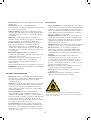 7
7
-
 8
8
-
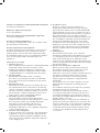 9
9
-
 10
10
-
 11
11
-
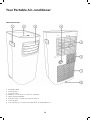 12
12
-
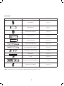 13
13
-
 14
14
-
 15
15
-
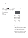 16
16
-
 17
17
-
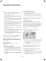 18
18
-
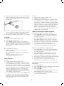 19
19
-
 20
20
-
 21
21
-
 22
22
-
 23
23
-
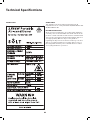 24
24
-
 25
25
-
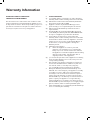 26
26
-
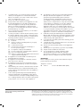 27
27
-
 28
28


Solt GGSAP2560W User manual
- Category
- Mobile air conditioners
- Type
- User manual
Ask a question and I''ll find the answer in the document
Finding information in a document is now easier with AI
Other documents
-
Inalto IAP2740W User manual
-
Midea MPPT-12CRN7 Owner's manual
-
-
Insignia NS-AC08PWH1 User guide
-
Airwell MFH - Mobile Owner's manual
-
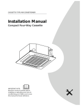 Kaisai KCA3U-18HRF32X Installation guide
-
Keystone KSTAW08INV User manual
-
Keystone KSTAW08INV-HC User manual
-
SystemAir SYSPLIT DUCT 24 LNS HP Q Owner's manual
-
Comfee 2,6kW Portable Air Conditioner User manual
