MSA Ultima Series Owner's manual
- Category
- Carbon monoxide (CO) detectors
- Type
- Owner's manual
This manual is also suitable for

Ultima
®
/Ultima
®
X
Series Controller
and Calibrator
Instruction Manual
THIS MANUAL MUST BE CAREFULLY READ BY ALL INDIVIDUALS WHO HAVE OR WILL
HAVE THE RESPONSIBILITY FOR USING OR SERVICING THE PRODUCT. Like any piece
of complex equipment, this instrument will perform as designed only if it is used and
serviced in accordance with the manufacturer’s instructions. OTHERWISE, IT COULD
FAIL TO PERFORM AS DESIGNED AND PERSONS WHO RELY ON THIS PRODUCT FOR
THEIR SAFETY COULD SUSTAIN SEVERE PERSONAL INJURY OR DEATH.
The warranties made by Mine Safety Appliances Company with respect to the product
are voided if the product is not used and serviced in accordance with the instructions
in this manual. Please protect yourself and others by following them. We encourage
our customers to write or call regarding this equipment prior to use or for any additional
information relative to use or repairs.
IN the U.S., to contact your nearest stocking location, dial toll-free 1-800-MSA-INST.
To contact MSA International, dial1-412- 967-3354
© MINE SAFETY APPLIANCES COMPANY 2010 - All Rights Reserved
This manual is available on the internet at www.msanet.com
Manufactured by
MSA NORTH AMERICA
P.O. Box 427, Pittsburgh, Pennsylvania 15230
(L) Rev 13 813379
"
WARNING

MSA Permanent Instrument Warranty
1. Warranty- Seller warrants that this product will be free from
mechanical defect or faulty workmanship for a period of two years
from date of shipment, provided it is maintained and used in
accordance with Seller's instructions and/or recommendations. This
warranty does not apply to expendable or consumable parts whose
normal life expectancy is less than one (1) year such as, but not
limited to, non-rechargeable batteries, filament units, filter, lamps,
fuses etc. The Seller shall be released from all obligations under
this warranty in the event repairs or modifications are made by
persons other than its own or authorized service personnel or if the
warranty claim results from physical abuse or misuse of the
product. No agent, employee or representative of the Seller has
any authority to bind the Seller to any affirmation, representation or
warranty concerning the goods sold under this contract. Seller
makes no warranty concerning components or accessories not
manufactured by the Seller, but will pass on to the Purchaser all
warranties of manufacturers of such components.
THIS WARRANTY IS IN LIEU OF ALL OTHER WARRANTIES,
EXPRESSED, IMPLIED OR STATUTORY, AND IS STRICTLY
LIMITED TO THE TERMS HEREOF. SELLER SPECIFICALLY
DISCLAIMS ANY WARRANTY OF MERCHANT ABILITY OR OF
FITNESS FOR A PARTICULAR PURPOSE.
2. Exclusive Remedy- It is expressly agreed that Purchaser's sole
and exclusive remedy for breach of the above warranty, for any
tortious conduct of Seller, or for any other cause of action, shall be
the repair and/or replacement at Seller's option, of any equipment
or parts thereof, which after examination by Seller is proven to be
defective. Replacement equipment and/or parts will be provided at
no cost to Purchaser, F.O.B. Seller's Plant. Failure of Seller to
successfully repair any non-conforming product shall not cause the
remedy established hereby to fail of its essential purpose.
3. Exclusion of Consequential Damage- Purchaser specifically
understands and agrees that under no circumstances will seller be
liable to purchaser for economic, special, incidental or
consequential damages or losses of any kind whatsoever, including
but not limited to, loss of anticipated profits and any other loss
caused by reason of non-operation of the goods. This exclusion is
applicable to claims for breach of warranty, tortious conduct or any
other cause of action against seller.

i
Chapter 1,
General Information . . . . . . . . . . . . . . . . . . . .1-1
Figure 1-1. Ultima Calibrator . . . . . . . . . . . . . . . . . .1-1
Three Function Operation . . . . . . . . . . . . . . . . . . . . . .1-2
Figure 1-2. Pointing the Calibrator
at the Ultima Gas Monitor Display . . . . . . . . .1-2
The Ultima/Ultima X Controller (FIGURE 1-3): . . . . . .1-3
Figure 1-3. Ultima/Ultima X Controller . . . . . . . . . . .1-3
Setting up the Controller . . . . . . . . . . . . . . . . . . . . . . . .1-4
Using the ID CODE Feature . . . . . . . . . . . . . . . . . . . .1-4
To Enable or Change the Password ID . . . . . . . . . . . .1-4
To Disable the Password ID . . . . . . . . . . . . . . . . . . . .1-4
Turning the Controller ON . . . . . . . . . . . . . . . . . . . . . .1-4
Turning the Controller OFF . . . . . . . . . . . . . . . . . . . . .1-5
Setting the Controller
for an Ultima or Ultima X Series Instrument . . . . . . . .1-5
Setting the Internal TIME of the Controller . . . . . . . . .1-5
Setting the Internal DATE of the Controller . . . . . . . . .1-6
When Sending a Command
to the Ultima/Ultima X Series Gas Monitor . . . . . . . . .1-6
Note on Resetting latched Alarms . . . . . . . . . . . . . . . .1-7
Chapter 2,
Calibration . . . . . . . . . . . . . . . . . . . . . . . . . . . .2-1
Equipment Required . . . . . . . . . . . . . . . . . . . . . . . . . .2-1
" WARNING . . . . . . . . . . . . . . . . . . . . . . . . . . . . .2-2
Span Gas Values . . . . . . . . . . . . . . . . . . . . . . . . . . . . . .2-2
" WARNING . . . . . . . . . . . . . . . . . . . . . . . . . . . . .2-2
Table 2-1. Factory-set Span Values . . . . . . . . . . . .2-3
Figure 2-1. Calibration Kit 40 Contents . . . . . . . . . .2-4
Figure 2-2. Calibration Kit 41 Contents . . . . . . . . . .2-5
Figure 2-3. Calibration Kit 54 Contents . . . . . . . . . .2-6
Table 2-2. Calibration Guide
for Combustible Gas Sensor . . . . . . . . . . . . .2-7
Ultima/Ultima X Series Gas Monitor Calibration . . . . . .2-9
" WARNING . . . . . . . . . . . . . . . . . . . . . . . . . . . . .2-9

INITIAL Calibration . . . . . . . . . . . . . . . . . . . . . . . . . . .2-10
Regular Calibration . . . . . . . . . . . . . . . . . . . . . . . . . .2-11
Zeroing . . . . . . . . . . . . . . . . . . . . . . . . . . . . . . . . . . . .2-11
Spanning . . . . . . . . . . . . . . . . . . . . . . . . . . . . . . . . . .2-13
Figure 2-5. Ultima X Unit - Apply SPAN Gas Flag 2-13
Figure 2-4. Ultima Unit - Apply SPAN Gas Flag . .2-13
Figure 2-6. Span Set-up (Ultima unit shown) . . . .2-14
Figure 2-7. Ultima X Series Unit
Calibration End Display . . . . . . . . . . . . . . . .2-15
Figure 2-8. Span Gas Connection
(Ultima unit shown) . . . . . . . . . . . . . . . . . . .2-15
OXYGEN Calibration . . . . . . . . . . . . . . . . . . . . . . . . .2-16
25% Oxygen Ultima/Ultima X Series Gas Monitor . .2-17
XIR Calibration . . . . . . . . . . . . . . . . . . . . . . . . . . . . . .2-17
" WARNING . . . . . . . . . . . . . . . . . . . . . . . . . . . .2-17
Chapter 3,
Controller - Detailed Operation . . . . . . . . . . .3-1
Viewing the Ultima Gas Monitor Display Modes . . . . . .3-1
Table 3-1. (see "Procedures") The Controller Can
Change the Display to Show: . . . . . . . . . . . . .3-1
To View the Status of the Monitor . . . . . . . . . . . . .3-2
Procedures (see TABLE 3-1) . . . . . . . . . . . . . . . . . . . . .3-3
Procedure 1. Setting the Average Time Interval . . . . .3-3
To Change the Average Time Interval . . . . . . . . . . .3-3
Procedure 2. Setting the Span Value . . . . . . . . . . . . .3-3
To Change the Calibration Span Gas Value
of the Ultima Sensor . . . . . . . . . . . . . . . . . . . . . . . .3-3
To Change the Calibration Span Gas Value
of the Ultima X Series Sensor . . . . . . . . . . . . . . . . .3-4
Procedure 3.
Setting the Range on an Ultima X Series Sensor . . . .3-5
Procedure 4
Setting the Gas Table for the Ultima XIR Sensor . . . .3-6
Procedure 5.
Setting the Three
Ultima Gas Monitor Alarm Setpoint Values . . . . . . . . .3-7
ii

To set the three levels of alarm: . . . . . . . . . . . . . . .3-7
Setting the Three Ultima X Series
Gas Monitor Alarm Setpoint Values . . . . . . . . . . . . .3-8
To set the three levels of alarm: . . . . . . . . . . . . . . .3-8
Enabling/Disabling and Setting
the Mode of the Three Ultima Alarm Setpoints . . . .3-9
Enabling/Disabling and setting the Mode
of theThree Ultima X Series Alarm Setpoints . . . .3-10
Procedure 6. Setting the Current Time . . . . . . . . . . .3-11
To update the Ultima Gas Monitor internal clock: .3-11
Procedure 7. Setting the Current Date . . . . . . . . . . .3-11
To update the Ultima Gas Monitor internal date: . .3-12
Procedure 8.
Enabling/Disabling Ultima Gas Monitor
Calibration Output Signal . . . . . . . . . . . . . . . . . . . . . .3-12
To enable or disable the calibration output signal: 3-12
Procedure 9.
Setting the Number of Days Between
Ultima Gas Monitor Auto-calibration Periods . . . . . . .3-13
Setting Time that Ultima Gas Monitor
Auto-calibration is to begin: . . . . . . . . . . . . . . . . . .3-13
Procedure 10.
Setting the Date of the Next Scheduled
Ultima Gas Monitor Calibration . . . . . . . . . . . . . . . . .3-14
Procedure 11. Changing the MUX Address . . . . . . . .3-14
To Change the Address . . . . . . . . . . . . . . . . . . . . .3-15
Procedure 12.
Viewing the Previous Successful Calibration Date . .3-15
Procedure 13.
Calibrating/Checking
the 4-20 mA Ultima X Series Outputs . . . . . . . . . . . .3-15
Procedure 14. Resetting Ultima X Series Monitors . .3-16
Procedure 15. Setting the Alert Option
on an Ultima X Series Sensor . . . . . . . . . . . . . . . . . .3-17
Table 3-2. Alert Operation Settings . . . . . . . . . . .3-17
Procedure 16.
Setting the Sensor Swap Delay
on an Ultima X Sensor . . . . . . . . . . . . . . . . . . . . . . . .3-17
iii

Procedure 17.
Setting an Unused Sensor to the Disabled Mode . . .3-18
Procedure 18. Setting the MODBUS BAUD rate. . . .3-19
Programming the Controller . . . . . . . . . . . . . . . . . . . . .3-19
Removing Existing Programs . . . . . . . . . . . . . . . . . .3-19
Adding a New Program . . . . . . . . . . . . . . . . . . . . . . .3-20
To Use Programs 1 through 4 . . . . . . . . . . . . . . . . . .3-20
To use Program #0 . . . . . . . . . . . . . . . . . . . . . . . . . .3-21
Section 4,
Maintenance . . . . . . . . . . . . . . . . . . . . . . . . . .4-1
" WARNING . . . . . . . . . . . . . . . . . . . . . . . . . . . . .4-1
Batteries . . . . . . . . . . . . . . . . . . . . . . . . . . . . . . . . . . . . .4-1
Determining a Low Battery Condition
on the Ultima Controller . . . . . . . . . . . . . . . . . . . . . . . .4-1
To Determine if Battery Replacement is Necessary . .4-1
Replacing the Batteries . . . . . . . . . . . . . . . . . . . . . . . .4-1
To Install New Batteries in the Ultima Controller . . . . .4-1
Determining a Low Battery Condition
on the Ultima Calibrator . . . . . . . . . . . . . . . . . . . . . . . .4-2
To Install New Batteries in the Ultima Calibrator . . . . .4-2
Service . . . . . . . . . . . . . . . . . . . . . . . . . . . . . . . . . . . . . .4-3
Troubleshooting Guidelines . . . . . . . . . . . . . . . . . .4-3
" WARNING . . . . . . . . . . . . . . . . . . . . . . . . . . . . .4-3
iv

1-1
Chapter 1,
General Information
This manual describes the operation and use of the Ultima Controller
and Ultima Calibrator for the Ultima Gas Monitor and the X Series Gas
Monitors. It is strongly recommended that this entire manual be read
before using the controller or the calibrator.
The controller and calibrator use an Infrared (IR) LED to transmit to an
IR receiver in the Ultima/Ultima X Series Gas Monitor.
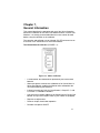
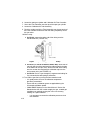
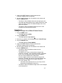
The Ultima/Ultima X Calibrator (FIGURE 1-1):
• Is a hand-held, self-contained unit powered by two internal AAA
batteries
• Allows one person, nonintrusive calibration of an Ultima/Ultima X
Series Gas Monitor, enabling the Monitor to be calibrated at the
unit without opening the enclosure
• Is listed as Intrinsically Safe for Classification I, Groups B, C, and
D, Division 1, Hazardous Locations
• Can select the multiplex address of an Ultima/Ultima X Series Gas
Monitor set up in the multiplex mode (if your monitor is equipped)
• Requires no adjustments
• Features simple, three-button operation
• Provides Auto power ON/OFF.
Figure 1-1. Ultima Calibrator

1-2
Three Function Operation
The Ultima Calibrator is equipped with three buttons for the following
functions:
1. ZERO Button:
• Performs a zero function on the Ultima/Ultima X Series Gas
Monitor; periodically, the monitor may require only a zero
adjustment.
2. CALIBRATE Button:
• Performs a zero and span calibration function on the
Ultima/Ultima X Series Monitor; During a complete calibration,
the Ultima Gas Monitor requires both a zero and span
check gas.
3. ADDRESS Button:
• Displays or changes the multiplex address on the
Ultima/Ultima X Series Monitor, if so equipped.
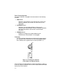
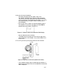
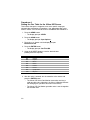
To Operate:
• All Ultima Calibrator operations are performed by simply pointing
the Calibrator at the Ultima/Ultima X Series Gas Monitor display
from a distance of no greater than six inches (FIGURE 1-2).
Communication to the Ultima/Ultima X Series Gas Monitor is made via
a one way, digitally encoded IR link to ensure tamper-proof and reliable
nonintrusive communication.
Figure 1-2. Pointing the Calibrator
at the Ultima Gas Monitor Display

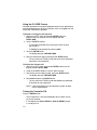
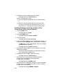
The Ultima/Ultima X Controller (FIGURE 1-3):
• Allows non intrusive calibration of an Ultima/Ultima X Series Gas
Monitor, enabling the Monitor to be calibrated at the unit without
opening the enclosure
• Is a hand-held, self-contained unit powered by
two internal AA batteries
• Is certified as Intrinsically Safe for Classification I, Groups B, C and
D, Division 1, Hazardous Locations
• Can select the following on an Ultima/Ultima X Gas Monitor:
• Set Monitor time and date
• Set the average interval
• Set/display span gas value
• Set/display alarms
• Display minimum, maximum, and average gas readings
• Enable calibration output signal
• Configure auto-calibration feature
• Display previous calibration date
• Set/display address
• Mimic Calibrator
• Set/Display Range (Ultima X Series units only)
Setting up the Controller
Figure 1-3. Ultima/Ultima X Controller
1-3

Using the ID CODE Feature
Controller operation can be password-protected to prevent operation by
unauthorized personnel. All Ultima Controller units are shipped from the
factory with Password ID disabled.
To Enable or Change the Password ID
1. With the unit OFF, press and hold the ENTER button for
approximately five seconds, until the display prompts:
ID KEY ####.
2. Use the NUMBER buttons:
• To CHANGE password ID by entering the old ID number
(go to step 3)
• To ENABLE a password ID by entering 9999.
3. Press the ENTER button.
• The display prompts: NEW KEY ####.
4. Enter the desired four-digit ID and press the ENTER button.
• The unit enters the READY mode and saves the ID password
required for future operation.
To Disable the Password ID
1. With the unit OFF, press and hold the ENTER button until the
display prompts: ID KEY ####.
2. Using the NUMBER buttons, enter the old ID number.
3. After entering the four-digit number, press the ENTER button.
• The display prompts: NEW KEY ####.
4. Enter 9999 and press the ENTER button.
• The unit enters the READY mode and disables the password
ID function for future operation.
NOTE: If the ID password is set and forgotten, contact an MSA
service representative.
Turning the Controller ON
Press the ENTER button.
• The unit performs a self-test and displays the firmware version
for several seconds
• If unit displays the Ultima READY or UltimaX READY prompt,
it is ready for use
1-4

1-5
• If unit displays the ID CODE prompt, enter the user-selected
password ID (see "Using the ID CODE Feature").
Turning the Controller OFF
• The unit turns OFF automatically approximately 100 seconds after
the last button is pressed
• To manually turn OFF the unit, press and hold the CLEAR button
for five seconds.
NOTE: A dual beep tone sounds when CLEAR button is pressed.
Setting the Controller
for an Ultima or Ultima X Series Instrument
The Ultima Controller features the capability to transmit to both the
Ultima and Ultima X Series instruments. To select the target instrument:
1. Turn unit ON to place it into the READY mode.
• Display prompts: Ultima READY or UltimaX READY.
(see "Turning the Controller ON.")
2. Press the DISPLAY button once.
• Display prompts: 0=ULTMA 1=ULTMX.
3. Enter "0" to set the controller for an Ultima instrument
or "1" to set the controller for an Ultima X Series instrument.
a. If your entry is valid, the controller will display "ULTIMA
READY" or "ULTIMAX READY".
b. If your entry is invalid, it will not be accepted. Start this
procedure again to change the controller type.
Setting the Internal TIME of the Controller
The Ultima/Ultima X Controller features an internal real time clock for
time/date stamping. To set the real time clock:
NOTE: Momentarily pressing the TIME button displays the current
hours and minutes. Press the CLEAR button to return to the
READY mode.
1. Place unit in the READY mode.
• Display prompts: "ULTIMA READY" or "ULTIMAX READY".
(see "Turning the Controller ON").
2. Press and hold TIME button until the HH:MM prompt appears.
3. Using the NUMBER buttons, enter the current time in 24-hour

format (e.g.: 4:00 P.M. = 16:00). (Leading zeros are required.)
a. If your entry is valid, press ENTER button to save this time.
b. If your entry is invalid, it will not be accepted; re-enter the
correct time or press the CLEAR button to cancel
and start over.
• The DEL button allows for correction during entry.
Setting the Internal DATE of the Controller
NOTE: Momentarily pressing the DATE button displays the
current date.
1. Place unit in the READY mode.
• Display prompts: "ULTIMA READY" or "ULTIMAX READY".
2. Press and hold the DATE button until the MM-DD-YYYY prompt
appears. (Leading zeros are required.)
3. Enter the current date using the NUMBER buttons.
a. If your entry is valid, press ENTER button to save that date.
b. If your entry is invalid, it will not be accepted; re-enter date
or press the CLEAR button to cancel and start this
procedure again.
• The DEL button allows for correction during entry.
When Sending a Command
to the Ultima/Ultima X Series Gas Monitor
1. The Controller must be READY prior to any key press.
2. To change any function on the Ultima/Ultima X Series Gas Monitor,
point the top of the controller directly at the clear face of the sensor
(FIGURE 1-2) and press the desired sequence of controller
buttons. (The controller must be pointed at the sensor when the
final button of sequence is pressed.)
• The top surface of the controller must be within six inches of
the sensor face to enable reception
• Each button pressed is acknowledged by a short beep
• The CLEAR button is acknowledged by a double beep
• When invalid responses are entered, the controller resets
to the READY mode or re-prompts user for a correct entry.
Note on Resetting latched Alarms
When an Ultima/Ultima X Gas Monitor has an active latched alarm
1-6

(indicated by a flashing alarm display):
• An infrared (IR) remote device (such as the Ultima Calibrator or
Ultima Controller) may be used to reset this alarm.
• If an Ultima/Ultima X Series Gas Monitor has an active latched
alarm, the next IR command it receives from a calibration device
will reset the latched alarm (if it is not beyond the alarm threshold).
The intended IR command will be ignored and interpreted as an
’alarm reset’. When the latching alarm function is inactive, other
valid IR commands may be use.
1-7

Chapter 2,
Calibration
The Ultima/Ultima X Series Gas Monitor provides non-intrusive
calibration through the use of the Ultima Controller/Calibrator.
When calibrating any Ultima/Ultima X Series Gas Monitor which has
any accessory attached to it, refer to the accessory manual for complete
calibration instructions. Some accessories for the Ultima/Ultima X
Series Gas Monitor include:
• Ultima Sampling Module
• Ultima Auto-Cal Module.
While factory calibration is standard practice for the Ultima/Ultima X
Series Gas Monitors, it is recommended to perform an INITIAL
calibration when first placing the unit into operation. Refer to the
"Initial Calibration" portion of this Chapter.
It is good practice to read the appropriate calibration instructions before
attempting an actual calibration. Also, identify and become familiar with
all of the calibration components. During the calibration, it is necessary
to quickly apply the span gas to the unit. Prior connection of the
calibration components will aid in ease of unit calibration.
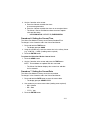
Equipment Required
Three calibration kits (numbered 40, 41, and 54; see FIGURES 2-1, 2-2,
and 2-3) are available from MSA for diffusion Ultima/Ultima X Series
Gas Monitors. Kit 40, 41, and 54 are housed in a convenient carrying
case and contain all items necessary (less gas) for a complete and
accurate calibration.
These Kits do not calibrate Ultima Sampling Modules or an
Ultima/Ultima X Series unit equipped with a flow cap. For flow or
sample module systems, refer to the Ultima Aspirated Sampling Module
Manual (P/N 710200) or to the Ultima DC Pump Sampling Module
Manual (P/N 710201).
NOTE: The calibration procedure for the sample draw Ultima XE/XA
Monitor is the same as the procedure for the diffusion version,
except calibration gas is applied to the calibration entry port of
the inlet flow block, and the cal kit for pumped units provides a
flow matching regulator.
2-1

The check or calibration gases can also be carried in the case. See
TABLE 2-1 for the appropriate zero and span gas cylinders for your
Ultima/Ultima X Series Gas Monitor.
TABLE 2-1 shows the recommended calibration kit for Ultima and
Ultima X Series Gas Monitors. Typically, Cal Kit 41 uses a 0.25 LPM
regulator and a calibration cap to contain the calibration gas.
Cal Kits 40 and 54 use a 1.5 LPM regulator and no calibration cap.
If Cal Kit 41 is recommended and the application is such that the
calibration cap cannot be used (such as for a remote sensor
application), Cal Kit 40 may be used. However, any time Cal Kit 40 is
used, ambient wind conditions must be minimized to avoid a calibration
with increased sensitivity.
NOTE: The Ultima XIR uses Cal Kit 40 and does require a calibration
cap. This calibration cap (P/N 10041533) is shipped with
the product.
These calibration kits contain zero caps to use in place of
zero calibration gas. These caps can only be used when
the ambient air does not contain the gas the monitor is
detecting. If there is any doubt, use zero gas when zeroing
the Ultima X Monitor; otherwise, improper calibration
could occur.
Span Gas Values
The Ultima/Ultima X Monitor is factory-shipped with a preset span gas
value (TABLE 2-1). This span gas value can be changed via the Ultima
Controller; otherwise, the span gas must correspond to preset
concentrations. See Section 3 to change the span gas value. The span
gas value of Ultima/Ultima X Gas Monitor catalytic combustible models
are pre-set to one of the broad categories shown in TABLE 2-1. Specific
span gas values for all combustible models are listed under each
category given in TABLE 2-2.
Always calibrate for the least sensitive gas or vapor (higher
number category) expected to be measured (TABLE 2-2);
otherwise, instrument readings may be incorrect.
"
WARNING
"
WARNING
2-2

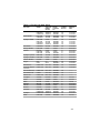
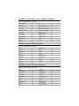
Table 2-1. Factory-set Span Values
GAS TYPE RANGE SPAN GAS MSA RP CALIBRA- WARM-UP
PRESET CYLINDER TION KIT TIME
VALUES P/N
Carbon Monoxide 0-100 PPM 60 PPM 710882 40 15 minutes
0-500 PPM 300 PPM 10027938 40 15 minutes
0-1000 PPM 400 PPM 10028048 40 15 minutes
Sulfur Dioxide 0-25 PPM 10 PPM 10028070 40 15 minutes
0-100 PPM 10 PPM 10028070 40 15 minutes
Hydrogen Sulfide 0-10 PPM 5 PPM 710414 40 15 minutes
0-50 PPM 40 PPM 10028062 40 15 minutes
0-100 PPM 40 PPM 10028062 40 15 minutes
0-500 PPM 250 PPM 10089547 40 15 minutes
Nitric Oxide 0-100 PPM 50 PPM 10028074 40 15 minutes
Nitrogen Dioxide 0-10 PPM 5 PPM 710332 41 30 minutes
Chlorine 0-5 PPM 2 PPM 710331 41 30 minutes
0-10 PPM 2 PPM 710331 41 30 minutes
0-20 PPM 10 PPM 10028066 41 30 minutes
Hydrogen Cyanide 0-50 PPM 10 PPM 10028072 41 30 minutes
Hydrogen Fluoride
(7)
0-10 PPM 8 PPM 10028070 41 30 minutes
Chlorine Dioxide
(4)
0-3 PPM 1 PPM 710331 41 30 minutes
Oxygen 0-5% 5% 493580 40 15 minutes
0-25% 20.8% 10028028
(2)
40 15 minutes
Natural Gas
(3)
0-100% LEL 25% LEL
(1)
10028034 40 15 minutes
Petroleum Vapors
(3)
0-100% LEL 40% LEL
(1)
10028034 40 15 minutes
(Gasoline)
General Solvents
(3)
0-100% LEL 55% LEL
(1)
10028034 40 ---------
Non-Methane IR 0-100% 29% LEL
(1)
10028034 40 ---------
Methane IR 0-100% LEL 50% LEL
(5)
10028032 40 ---------
Phosphine 2.0 PPM 0.5 PPM 710533 41 24 hours
Arsine 2.0 PPM 1.0 PPM 710533 41 24 hours
Silane 25 PPM 5 PPM 10014897 41 4 hours
Diborane 50 PPM 15 PPM 10014897 41 30 minutes
Fluorine 5.0 PPM 4.0 PPM 710331 41 30 minutes
Bromine 5.0 PPM 2.5 PPM 710331 41 30 minutes
Ammonia 0-50 PPM 25 PPM 10028076 40 30 minutes
0-1000 PPM 300 PPM 10044014 40 30 minutes
Hydrogen 0-1000 PPM 500 PPM 10022386 40 30 minutes
ETO
(6)
0-10 PPM 4.0 PPM 10028070 40 24 hours
2-3

GAS TYPE RANGE SPAN GAS MSA RP CALIBRA- WARM-UP
PRESET CYLINDER TION KIT TIME
VALUES P/N
Carbon Dioxide IR 0-5000 PPM 2000 PPM 479266 40 ---------
0-2% 1.5% 807386 40 ---------
0-5% 2.5% 479265 40 ---------
Hydrogen Chloride 0-50 PPM 40 PPM 10028078 54 30 minutes
NOTES:
1
Calibrated with PROPANE (.6% GAS BY VOLUME)
2
Not required for standard calibration procedure
3
For Combustible Gas, it is good practice to calibrate unit with gas to be detected
4
ClO
2
is calibrated with Cl
2
or use ClO
2
Calibrator Kit (P/N 710420)
5
Methane IR is calibrated with 50% LEL Methane
6
ETO is calibrated with SO
2
.
7
Hydrogen Fluoride (HF) is calibrated with Sulfur Dioxide (SO
2
), 10 PPM SO
2
= 8 PPM HF
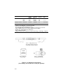
Figure 2-1. Calibration Kit 40 Contents
(Your Kit may also include one or two gas cylinders)
Item 2 - Zero Cap
(P/N 710535)
Item 3 - 1.5 LPM Flow
Controller (P/N 478358)
Item 1 - Tubing (P/N 711112)
- 3/16" ID side connects to Item 3
- 1/4" ID side connects to sensor
2-4

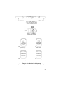
Figure 2-2. Calibration Kit 41 Contents
(Your Kit may also include one or two gas cylinders)
Item 5 - Calibration Cap
(P/N 10020030)
Item 6 - Zero Cap
(P/N 710535)
Item 3 - Calibration Cap
(P/N 710411)
Item 4 - Zero Cap
(P/N 813774)
Item 2 - .25 LPM Flow
Controller (P/N 478359)
Item 1 - Tubing (P/N 711112)
- 3/16" side connects to Item 2
- 1/4" side connects to sensor
2-5

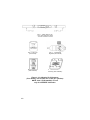
Figure 2-3. Calibration Kit 54 Contents
(Your Kit may also include one or two gas cylinders)
NOTE: Item 5 (P/N 10066581) is used
only for SAFEMTX Calibration
Item 4 - Desiccant
(P/N 10064306)
Item 5 - Calibration Cover
Assembly (P/N 10066581)
Item 2 - Zero Cap
(P/N 710535)
Item 3 - 1.5 LPM Flow
Regulator (P/N 478358)
Item 1 - Tubing (P/N 711112)
- 3/16" side connects to Item 2
- 1/4" side connects to sensor
2-6

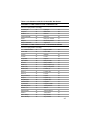
Table 2-2. Calibration Guide for Combustible Gas Sensor
CATEGORY 31: FOR CATALYTIC TYPE 1S NATURAL GAS
To detect the following gases, recalibrate with 0.6% propane
and set the span gas value accordingly:
Acetaldehyde 23 Hydrogen 16
Acetylene 24 MAPP Gas 20
Butadiene, 1, 3 25 Methane 20
Carbon Monoxide 20 Methanol 20
Ethane 24 Methylene Chloride 24
Ethylene 25 Monomethyl Amine 22
Ethylene Dichloride 22 Trigonox B 22
CATEGORY 32: FOR CATALYTIC TYPE 1S PETROLEUM VAPORS
To detect the following gases, recalibrate with 0.6% propane
and set the span gas value accordingly:
1, 1, 1-Trichloroethane 32 Ethylene Oxide 36
Acetic Acid 28 Freon 152A 28
Acetone 37 Gasoline 35
Acrolein 28 Hexane 40
Acrylonitrile 26 Isoprene 33
Allyl chloride 30 Methyl Acetate 34
Benzene 37 Methyl chloride 32
Butane (n) 36 Methyl Propene (2) 29
Butane (iso) 32 Methyl t-Butyl Ether 35
Butanol (iso) 38 Pentane (n) 36
Butene-1 34 Pentane (iso) 36
Butene-2 37 Pentene 35
Butyl Acetate (n) 28 Propane 29
Butylene 33 Propanol (n) 36
Butyraldehyde 30 Propanol (iso) 37
Chlorobenzene 38 Propylene 33
Cyclohexane 37 Propylene Oxide 33
Dimethoxyethane 26 Tetrahydrofuran 30
Dioxane, 1, 4 39 Toluene 39
Epichlorhydrin 33 Trichloroethylene 35
Ethanol 30 Triethylamine 38
Ether, Diethyl 37 Vinyl Acetate 34
Ether, Dimethyl 30 Vinyl Chloride 32
2-7
Page is loading ...
Page is loading ...
Page is loading ...
Page is loading ...
Page is loading ...
Page is loading ...
Page is loading ...
Page is loading ...
Page is loading ...
Page is loading ...
Page is loading ...
Page is loading ...
Page is loading ...
Page is loading ...
Page is loading ...
Page is loading ...
Page is loading ...
Page is loading ...
Page is loading ...
Page is loading ...
Page is loading ...
Page is loading ...
Page is loading ...
Page is loading ...
Page is loading ...
Page is loading ...
Page is loading ...
Page is loading ...
Page is loading ...
Page is loading ...
Page is loading ...
Page is loading ...
Page is loading ...
Page is loading ...
-
 1
1
-
 2
2
-
 3
3
-
 4
4
-
 5
5
-
 6
6
-
 7
7
-
 8
8
-
 9
9
-
 10
10
-
 11
11
-
 12
12
-
 13
13
-
 14
14
-
 15
15
-
 16
16
-
 17
17
-
 18
18
-
 19
19
-
 20
20
-
 21
21
-
 22
22
-
 23
23
-
 24
24
-
 25
25
-
 26
26
-
 27
27
-
 28
28
-
 29
29
-
 30
30
-
 31
31
-
 32
32
-
 33
33
-
 34
34
-
 35
35
-
 36
36
-
 37
37
-
 38
38
-
 39
39
-
 40
40
-
 41
41
-
 42
42
-
 43
43
-
 44
44
-
 45
45
-
 46
46
-
 47
47
-
 48
48
-
 49
49
-
 50
50
-
 51
51
-
 52
52
-
 53
53
-
 54
54


MSA Ultima Series Owner's manual
- Category
- Carbon monoxide (CO) detectors
- Type
- Owner's manual
- This manual is also suitable for
Ask a question and I''ll find the answer in the document
Finding information in a document is now easier with AI
Related papers
-
MSA Ultima® XIR Gas Monitor Quick start guide
-
-
-
-
-
-
-
MSA Ultima® X Series Gas Monitors Owner's manual
-
-
Other documents
-
Critical Environment Technologies CXT2 Operating instructions
-
Hach SC200 User manual
-
GBC 1710750 Datasheet
-
 BeamGrip FP Stryder™ Beam Anchor Owner's manual
-
Chord ULTIMA PRE User manual
-
Chord ULTIMA PRE 2 User manual
-
-
-
Chord Ultima 5 User manual
-
Chord ULTIMA 6 User manual
