Roland M-400 Owner's manual

Category
Audio equalizers
Type
Owner's manual

Roland M-400 is a versatile digital mixer that offers a wide range of features for both live sound and recording applications. With its 40 input channels, 24 mix buses, and 8 matrix outputs, the M-400 provides ample headroom for even the most complex productions. The built-in effects engine includes a variety of reverbs, delays, and modulation effects, while the GEQ and compressor/limiter on each channel provide precise sound shaping capabilities. The M-400 also features a built-in USB audio interface, making it easy to record and playback audio directly to and from a computer.

Roland M-400 is a versatile digital mixer that offers a wide range of features for both live sound and recording applications. With its 40 input channels, 24 mix buses, and 8 matrix outputs, the M-400 provides ample headroom for even the most complex productions. The built-in effects engine includes a variety of reverbs, delays, and modulation effects, while the GEQ and compressor/limiter on each channel provide precise sound shaping capabilities. The M-400 also features a built-in USB audio interface, making it easy to record and playback audio directly to and from a computer.

Version 2.1 Owner’s Manual Addendum
Copyright © 2010 ROLAND CORPORATION
All rights reserved. No part of this publication may be reproduced in any form without the written permission of ROLAND CORPORATION.
This document describes the features that have been added in this update.
In order to fully understand the M-400’s new features, please read this document together with the Owner’s Manual for the M-400.
M-400_v21Added_e.book 1 ページ 2010年1月28日 木曜日 午前8時56分
2
Functionality added in version 2.10
Connection to the S-400M and S-0808 is supported.(
p. 4)
.
A feature for making the input/output settings on the S-4000M has been added.
The M-400 does not support REAC EMBEDDED POWER. When you connect an S-0808, install an external battery on the S-0808 to power it via the DC IN
port. Note, however, that when the connection to the M-400 is made via an S-4000M or S-4000D, the S-0808 is powered by the S-4000M or S-4000D,
and so no external battery is required.
You can perform gate and compressor operations using the EQUALIZER area controls (
p. 10).
New functionality has been added to the user layers (
p. 14).
The user layers have been increased to three layers.
The method used to access the user layers has been changed.
Channel mute options have been added (
p. 16).
You can select whether to mute AUX sends and DIRECT OUTs when input channels are muted.
Indicators for the REAC A and B ports have been added at the top display area.
fig.REACStatus_Guide.eps
.
New functionality has been added to the user buttons.
Other Added Functionality
The port names in the top display area flash when no input has been assigned to the channel.
When “NO ASSIGN” is flashing, no input
i
s assigned to the channel.
fig.NoAssign.eps
When a port name such as “A: IN 1” is displayed, either the input/output unit at the corresponding REAC port is not connected correctly, or a
nonexistent input is assigned to the channel
fig.AIN1.eps
DD
DD
ii
ii
ss
ss
pp
pp
ll
ll
aa
aa
yy
yy
Description
Unlighted No REAC device connected
Flashing Establishing connection with REAC device
Lighted Normal connection with REAC device
FUNCTION
PARAM1 PARAM2 Button Explanation
EFFECT
EDIT GEQ
FX1
GEQ A
Lit when the specified screen is
displayed.
When FX1 through 4 are used as Dual GEQ, you access the
screen for each GEQ individually.
This is effective only for the FX using Dual GEQ.
FX1
GEQ B
FX2
GEQ A
FX2
GEQ B
FX3
GEQ A
FX3
GEQ B
FX4
GEQ A
FX4
GEQ B
M-400_v21Added_e.book 2 ページ 2010年1月28日 木曜日 午前8時56分
3
Functionality added in version 2.10
Display of the insert destination has been added to the GEQ EDIT and FX EDIT popups (Dual GEQ).
fig.GEQ_Guide.eps
A delay time indicator has been added to the "SDE-3000 x2" effect type.
This flashes in time with the delay time.
fig.Sde3000_Guide.eps
The user interface when using the top panel faders to control the GEQ have been improved.
The range of corresponding fader is displayed more clearly.
fig.GEQonFdr.eps
The user interface of the LOAD/SAVE popup have been changed.
You can move the folder on the project file list, and you can save and load project files in any desired folder.
The message “Completed.” is displayed when initialization of mixer settings finishes.
This is displayed when you have initialized the mixer settings using the INITIALIZE popup (SYSTEM screen > [F1 (INIT)]).
The patch symbols on the PATCHBAY screen have been changed to arrows.
Input patchbay patches are shown by an icon , and output patchbay patches are shown by an icon .
This makes the direction of signal flow easier to understand.
You can store scenes via the RS-232C.
For more information, refer to “RS-232C Reference Version 1.4.”
M-400_v21Added_e.book 3 ページ 2010年1月28日 木曜日 午前8時56分
4
S-4000M’s Input/Output Settings
Editing the S-4000M’s Input/Output Settings
The S-4000M has a Merge patchbay and an Output patchbay (Output
patchbay supports S-0808 8x8 I/O UNITS only). You can edit the S-4000M’s
Merge/Output patchbays using S-4000 RCS to change input/output
assignments.
Merge Patchbay
This merges the inputs of the REAC slave units (connected to the
REAC ports 1–4 of the S-4000M) into the channels to the M-400’s
REAC port.
Output Patchbay
This assigns channels from the M-400 to the outputs of the S-0808
units ( REAC ports 1–4).
You cannot edit an S-4000M’s input/output settings when the S-
4000M is set to the THRU mode.
The S-4000M input/output setup is saved to internal memory. The S-
4000M configuration window loads and displays the setup from the
connected S-4000M.
You can save/load the S-4000M input and output setups to a USB memory
as a S-4000M Input/Output Setup file (p. 9).
S-4000M’s input/output setups cannot be saved as part of scene
memory.
To edit S-4000M’s Merge/Output patchbay, use the S-4000M
CONFIGURATION popup.
fig.S4M_Config_Guide.eps
Slave device display
This part displays the REAC Slave devices connected to REAC ports 1–
4 of the S-4000M.
S-4000M Merge Patchbay
This part displays how the Slave devices are being patched through
the M-400.
PORT4 OPTION
Split Merged Inputs button
Check this button to send the merged inputs being sent to the M-400
out to REAC port 4 as well (p. 8).
The function buttons perform the following operations.
Storing Input/Output Setups
S-4000M CONFIGURATION popup
[F1 (MERGE)]
Displays MERGE tab.
[F2 (OUTPUT)] Displays OUTPUT tab.
[F4 (LOAD/SAVE)] Access the S-4000M LOAD/SAVE popup.
[F5 (AUTO MAP)] Resets the S-4000M Input/Output setup.
[F8 (CLOSE)] Closes the popup
1
2
3
1
2
3
M-400_v21Added_e.book 4 ページ 2010年1月28日 木曜日 午前8時56分
5
S-4000M’s Input/Output Settings
1.
In the SETUP section, press [SYSTEM] to access the
SYSTEM screen.
fig.System.eps
2.
Press [F2 (REAC CONFIG)].
The REAC CONFIG popup will appear.
3.
Select the target REAC port by pressing [F2 (REAC A)] or
[F3 (REAC B)].
fig.ReacConfig_S4000M.eps
4.
Press [F5 (S-4000M CONFIG)].
fig.S4M_Config1.eps
The S-4000M CONFIGURATION popup will appear.
You can reset and optimize the merge/output patchbays according to the
devices physically connected to REAC ports 1–4.
This has the same function as [AUTO MAP SLAVE UNITS] button on
S-4000M’s front panel.
1.
Access the S-4000M CONFIGURATION popup.
fig.S4M_Config1.eps
2.
Press [F5 (AUTO MAP)].
A confirmation message will ask you to confirm the operation.
3.
Press [F8 (OK)] to reset the S-4000M Input/Output setups.
Pressing [F7 (CANCEL)] will cancel the operation.
Accessing the S-4000M CONFIGURATION
popup
Resetting S-4000M Input/Output Setups
(System Reset)
M-400_v21Added_e.book 5 ページ 2010年1月28日 木曜日 午前8時56分
6
S-4000M’s Input/Output Settings
Merge Patchbay Operations
1.
Acesss the S-4000M CONFIGURATION popup.
2.
Press [F1 (MERGE)] to access the MERGE tab.
fig.S4M_Config_IN_Guide.eps
Merge Patchbay
This part displays overall view of the S-4000M’s merge patchbay.
You can move the cursor to the Merge Patchbay and press [ENTER] to
access the S-4000M MERGE PATCHBAY popup.
3.
Move cursor to the Merge Patchbay and press [ENTER].
fig.S4000MInputPatchbay.eps
The S-4000M MERGE PATCHBAY popup will appear.
Current Assign indication
This indicates the physical input source that is patched to the
channel at the cursor location.
Device indication
This indicates the REAC slave device that is selected by the function
buttons [F1 (PORT1)]–[F4 (PORT4)].
Patchbay grid
This grid lets you make patchbay settings.
fig.ScrInPatGridGuide.eps
REAC Channel indication
This indicates the number of the REAC channels being sent to the M-
400.
Input indication
This indicates the input numbers of the REAC slave device and the
signal level s.
The color indicates the signal level as follows.:
Patch symbol
A patch symbol is shown where the currently patched REAC channel
and input intersect. To change the patching, move the cursor to the
location where the desired REAC channel and input intersect, and
press [ENTER].
Unavailable area
The number area is shown in gray for inputs that cannot be used with
the currently connected REAC slave device.
The function buttons perform the following operations.
4.
Press [F1 (PORT1)]–[F4 (PORT4)] to select the desired S-
4000M’s REAC port.
5.
Move the cursor to the intersection of the desired REAC
channel and input, and press [ENTER].
1.
As described in step 1–4 of “Merge Patchbay Operations
(p. 6)”, access the S-4000M MERGE PATCHBAY popup.
2.
Press [F6 (CLEAR)].
fig.S4M_PatchChgConf.eps
A confirmation message will ask you to confirm the operation.
3.
Press [F8 (CLEAR)] to clear all assignments associated
with the currently selected S-4000M’s REAC port.
Pressing [F7 (CANCEL)] will cancel the operation.
1
1
2 34
2
3
4
1 2
3 4
Color
Signal Level
Black
Below -48dB
Green Between -48dB and -18dB
Yellow Above -18dB
[F1 (PORT1)]–
[F4 (PORT4)]
Selects the S-4000M’s REAC port
[F6 (CLEAR)] Clear all assignments of currently selected
REAC port.
[F8 (CLOSE)] Closes the popup
Clearing all assignments
1
2
3
4
M-400_v21Added_e.book 6 ページ 2010年1月28日 木曜日 午前8時56分
7
S-4000M’s Input/Output Settings
Output Patchbay Operations (S-0808)
1.
Access the S-4000M CONFIGURATION popup.
2.
Press [F2 (OUTPUT)] to access the OUTPUT tab.
fig.S4M_Config_OUT_Guide.eps
Output Patchbay
This part displays overall view of the S-4000M’s output patchbay.
You can move the cursor to the Output Patchbay and press [ENTER]
to access the S-4000M OUTPUT PATCHBAY popup.
3.
Move cursor to the desired Output Patchbay and press
[ENTER].
fig.S4000MIOutputPatchbay.eps
The S-4000M OUTPUT PATCHBAY popup will appear.
Current Assign indication
This indicates the channel that is patched to the physical output at
the cursor location.
Device indication
This indicates the REAC slave device that is that is the target of the S-
4000M OUTPUT pATCHBAY popup.
Patchbay grid
This grid lets you make patchbay settings.
fig.ScrOutPatGridGuide.eps
REAC Channel indication
This indicates the number and the signal level of the REAC channels
being sent from the M-400.
The color indicates the signal level as follows.:
Output indication
This indicates the output numbers of the REAC slave device.
Patch symbol
A patch symbol is shown where the currently patched REAC channel
and output intersect. To change the patching, move the cursor to the
location where the desired REAC channel and output intersect, and
press [ENTER].
Unavailable area
The number area is shown in gray for outputs that cannot be used
with the currently connected REAC slave device.
The function buttons perform the following operations.
4.
Move the cursor to the intersection of the desired REAC
channel and output, and press [ENTER].
1.
As described in step 1–3 of “Output Patchbay Operations
(S-0808) (p. 7)”, access the S-4000M OUTPUT PATCHBAY
popup.
2.
Press [F6 (CLEAR)].
fig.S4M_PatchChgConf.eps
A confirmation message will ask you to confirm the operation.
3.
Press [F8 (CLEAR)] to clear all assignments associated
with the currently selected S-4000M’s REAC port.
Pressing [F7 (CANCEL)] will cancel the operation.
1
1
2 34
2
3
4
1
2
3
4
Color
Signal Level
Black
Below -48dB
Green Between -48dB and -18dB
Yellow Between -18dB and 0dB
Red Above 0dB
[F6 (CLEAR)]
Clear all assignments.
[F8 (CLOSE)] Closes the popup
Clearing all assignments
1
2
3
4
M-400_v21Added_e.book 7 ページ 2010年1月28日 木曜日 午前8時56分
8
S-4000M’s Input/Output Settings
Splitting Merged Inputs (S-4000M's Split Function)
By using the S-4000M’s Split Function, you can split the merged inputs
(being sent to the M-400) to REAC port 4 of the S-4000M. It is very
convenient when splitting to a monitor console or a multi-channel
recording system.
fig.S4000MSplit.eps
When a REAC splitter (like the S-4000D) is connected to the S-
4000M’s REAC port A, the signal from the M-400 is split.
Notes About the S-4000M’s Split Function
* You can connect a REAC slave device to S-4000M’s REAC port 4
via a REAC splitter (like the S-4000D). In this case, the physical
inputs of the REAC slave device operate normally but all merged
inputs being sent to the M-400 will being sent out from the
physical outputs.
* If an M-48 is connected to the S-4000M’s REAC port 4, it is not
possible to manage/setup the M-48 from the M-400.
Using the S-4000M's split function makes it unnecessary to use the
M-400's output to REAC for stage-input splitting or recording.
1.
Access the S-4000M CONFIGURATION popup.
fig.S4M_Config1.eps
If the “Split Inputs to PORT4” button in the PORT4 OPTION is
checked, then the S-4000M’s split function is already turned on. The
following steps will not be necessary.
2.
Disconnect the REAC cable connected to REAC port 4 on
the S-4000M.
3.
Move cursor to the Split Merged Inputs button in the
PORT4 OPTION, and press [ENTER].
fig.S4M_SplitChgConf.eps
A confirmation message will ask you to confirm the operation.
4.
Press [F8 (OK)] to enable the S-4000M’s split function.
Pressing [F7 (CANCEL)] will cancel the operation.
fig.S4M_Config_Split.eps
fig.S4M_Config_Split_Out.eps
5.
Connect the REAC cable to REAC port 4 on the S-4000M.
REAC A or REAC B
MASTER
S-0808
S-4000M
SLAVE
1 1 1 1
SPLITSLAVE
S-4000S
(32-channel output)
PC Recording
S-4000D
2 3
A
1
4
Merged Inputs
Merged Inputs
(Split)
Using S-4000M’s split function
M-400_v21Added_e.book 8 ページ 2010年1月28日 木曜日 午前8時56分
9
S-4000M’s Input/Output Settings
Save/Load the S-4000M’s Input/Output Setups
You can save/load the S-4000M input and output setups to a USB memory
as a S-4000M Input/Output Setup file .
To save/load the S-4000M Input/Output Setup File, use the S-4000M
LOAD/SAVE popup.
1.
Access the S-4000M CONFIGURATION popup.
fig.S4M_Config1.eps
2.
Press [F4 (LOAD/SAVE)].
fig.S4M_LoadSave_Guide.eps
The S-4000M LOAD/SAVE popup will appear.
File list
This lists the S-4000M Input/Output Setup files that have been saved
to USB memory. You can specify the save-destination folder for the
file, or specify the file that you want to load.
The function buttons perform the following operations.
1.
Access the S-4000M LOAD/SAVE popup.
2.
Press [F2 (SAVE)].
fig.S4M_Save.eps
The S-4000M SAVE popup will appear.
3.
Edit the name of the S-4000M Input/Output Setup file in
the name edit field.
4.
When you press [F8 (SAVE)], a message indicating the
status of the save procedure will appear. When saving is
completed, the message will close.
Pressing [F7 (CANCEL)] will cancel the operation.
Do not disconnect the USB memory or switch off the M-400’s power
while data is being saved to USB memory. Doing so may destroy the
data saved in USB memory.
1.
Access the S-4000M LOAD/SAVE popup.
2.
In the file list, select the S-4000 Input/Output Setup file
that you want to load.
3.
Press [F1 (LOAD)].
fig.S4M_LoadConf.eps
A confirmation message will ask you to confirm the operation.
4.
When you press [F8 (LOAD)], a message indicating the
status of the load procedure will appear. When loading is
completed, the message will close.
Pressing [F7 (CANCEL)] will cancel the operation.
Do not disconnect the USB memory or switch off the M-400’s power
while data is being saved to USB memory. Doing so may destroy the
data saved in USB memory.
Accessing the S-4000M LOAD/SAVE
popup
[F1 (LOAD)]
Loads the S-4000M Input/Output Setup file
selected in the file list.
[F2 (SAVE)] Saves the S-4000M’s input/output setups.
[F3 (MAKE FOLDER)] Creates a folder in the file list.
[F4 (NAME EDIT)] Accesses the NAME EDIT popup where
you can edit the name of the file or folder.
[F5 (DELETE)] Deletes the selected file or folder from the
file list.
[F8 (CLOSE)] Closes the popup
1
1
Saving the S-4000M Input/Output Setup
file
Loading the S-4000M Input/Output
Setup file
M-400_v21Added_e.book 9 ページ 2010年1月28日 木曜日 午前8時56分
10
New Functionality for Dynamics
About the New Functionality for Dynamics
fig.ChEdtEQ.eps
You can now manipulate dynamics parameters using the EQUALIZER area knobs in the CHANNEL EDIT section.
When one of the following popups is displayed, you can use the Q, FREQ, and GAIN knobs for LO MID and HI MID to adjust the on-screen parameters.
GATE/EXPANDER popup
COMPRESSOR popup
LIMITER popup
In addition to the added functionality, the design of the popups has also been changed.
About the New Functionality for Dynamics
fig.LayerSectGuide.eps
TYPE select buttons
These select the gate/expander type from the following choices.
KEY-IN meter
This indicates the level of the key-in signal. For stereo-linked
channels, two meters are shown (L and R).
IN meter
This indicates the input level of the gate/expander. For stereo-linked
channels, two meters are shown (L and R).
GR meter
This indicates the amount of gain reduction produced by the gate/
expander.
Gate/expander graph
This indicates the approximate response of the gate/expander.
OUT meter
This indicates the output level of the gate/expander. For stereo-
linked channels, two meters are shown (L and R).
KEY-IN SELECT popup button
This accesses the KEY-IN SELECT popup where you can select the key-
in signal. For stereo-linked channels, there will be two (L and R). The
channel currently selected as the key-in signal is shown on the
button.
•When the GATE/EXPANDER popup is displayed, the gate/expander
can be adjusted using EQUALIZER area controls for the CHANNED
EDIT section. The FREQ, and GAIN knobs for EQ LO and HI are
disabled at this time. The parameters that you can manipulate using
the EQ area controls vary according to the state of the TYPE select
buttons, as shown below.
GATE
GATE/EXPANDER popup
GATE
Gate
EXPANDER Expander
DUCKING Ducking
1
2 3 4
5 6
7
1
2
3
4
Knob
Parameter
EQ LO-MID
Q Blink Threshold level
FREQ Blink ATTACK time
GAIN Blink RELEASE time
EQ HI-MID Q Blink RANGE
FREQ Unlit Disabled
GAIN Blink HOLD time
5
6
7
M-400_v21Added_e.book 10 ページ 2010年1月28日 木曜日 午前8時56分
11
New Functionality for Dynamics
EXPANDER
DUCKING
Gate
fig.PopGateGuide2.eps
THRESH knob
This adjusts the threshold level in a range of -80.0 dB–0.0 dB.
RANGE knob
This adjusts the RANGE in a range of -Inf dB–0.0 dB.
ATTACK knob
This adjusts the ATTACK time in a range of 0.0 ms–800.0 ms. This is
the time from when the input signal exceeds the threshold level until
the gate opens completely.
RELEASE knob
This adjusts the RELEASE time in a range of 0 ms–8000 ms. This is the
time over which the gate reaches its maximum effect after the HOLD
time has elapsed.
HOLD knob
This adjusts the HOLD time in a range of 0 ms–8000 ms. This is the
time from when the input signal falls below the threshold level until
the gate begins closing.
Expander
fig.PopExpGuide.eps
THRESH knob
This adjusts the threshold level in a range of -80.0 dB–0.0 dB.
RATIO knob
This adjusts the RATIO in a range of 1.00:1–INF:1 (14 steps).
KNEE knob
This adjusts the KNEE in a range of HARD or SOFT1–SOFT9 (ten steps).
The way in which the expander is applied to the region near the
threshold level can be adjusted between steep (HARD) and gentle
(SOFT9).
ATTACK knob
This adjusts the ATTACK time in a range of 0.0 ms–800.0 ms. This is
the time from when the input signal exceeds the threshold level until
the expander effect disappears.
RELEASE knob
This adjusts the RELEASE time in a range of 0 ms–8000 ms. This is the
time from when the input signal falls below the threshold level until
the expander effect reaches its maximum.
Ducking
fig.PopDuckGuide.eps
THRESH knob
This adjusts the threshold level in a range of -80.0 dB–0.0 dB.
RANGE knob
This adjusts the RANGE in a range of -Inf dB–0.0 dB.
ATTACK knob
This adjusts the ATTACK time in a range of 0.0 ms–800.0 ms. This is
the time from when the input signal exceeds the threshold level until
the ducking effect reaches its maximum.
Knob
Parameter
EQ LO-MID
Q Blink Threshold level
FREQ Blink ATTACK time
GAIN Blink RELEASE time
EQ HI-MID Q Blink RATIO
FREQ Blink KNEE
GAIN
Unlit
Disabled
Knob
Parameter
EQ LO-MID
Q Blink Threshold level
FREQ Blink ATTACK time
GAIN Blink RELEASE time
EQ HI-MID Q Blink RANGE
FREQ
Unlit
Disabled
GAIN Blink HOLD time
1 2
3
4 5
1
2
3
4
5
1 2
3
4
5
1
2
3
4
5
1 2
3
4 5
1
2
3
M-400_v21Added_e.book 11 ページ 2010年1月28日 木曜日 午前8時56分
12
New Functionality for Dynamics
RELEASE knob
This adjusts the RELEASE time in a range of 0 ms–8000 ms. This is the
time over which the ducking effect disappears after the HOLD time
has elapsed.
HOLD knob
This adjusts the HOLD time in a range of 0 ms–8000 ms. This is the
time from when the input signal falls below the threshold level until
the ducking effect begins to disappear.
fig.PopCompGuide.eps
KEY-IN meter
This indicates the level of the key-in signal. For stereo-linked
channels, two meters (L and R) are shown.
IN meter
This indicates the input level to the compressor. For stereo-linked
channels, two meters (L and R) are shown.
GR meter
This indicates the amount of gain reduction produced by the
compressor.
Compressor graph
This indicates the approximate response of the compressor.
OUT meter
This indicates the output level of the compressor. For stereo-linked
channels, two meters (L and R) are shown.
KEY-IN SELECT popup button
This accesses the KEY-IN SELECT popup window where you can select
the key-in signal. For stereo-linked channels, there are two buttons (L
and R). The channel currently selected as the key-in signal is shown
on the button.
THRESH knob
This adjusts the threshold level in a range of -40.0 dB–0.0 dB.
RATIO knob
This adjusts the RATIO in a range of 1.00:1–INF:1(14 steps).
KNEE knob
This adjusts the KNEE in a range of HARD to SOFT1–SOFT9 (ten steps).
The way in which the compressor applies to the region near the
threshold level can be adjusted between steep (HARD) and gradual
(SOFT9).
ATTACK knob
This adjusts the ATTACK time in a range of 0.0 ms–800.0 ms. This is
the time from when the input signal exceeds the threshold level until
the compressor reaches its maximum effect.
RELEASE knob
This adjusts the RELEASE time in a range of 0 ms–8000 ms. This is the
time from when the signal falls below the threshold level until the
compressor is no longer applied.
GAIN knob
This adjusts the GAIN in a range of -40.0 dB–+40.0 dB. This adjusts the
output level of the compressor.
If AUTO GAIN is on, the GAIN will have an effective range of -40.0
dB–+6.0 dB. If the GAIN value is outside the effective range, the
value will be shown in red.
When the COMPRESSOR popup is displayed, the compressor can be
adjusted using the EQ area controls for the CHANNEL EDIT section.
The FREQ, and GAIN knobs for EQ LO and HI are disabled at this
time. The parameter that you can manipulate using the EQ area is as
follows.
COMPRESSOR popup
4
5
1 2 3 4
5
7
8
9
10
11
6
12
1
2
3
4
5
6
7
8
9
Knob
Parameter
EQ LO-MID
Q Blink Threshold level
FREQ Blink ATTACK time
GAIN Blink RELEASE time
EQ HI-MID Q Blink RATIO
FREQ Blink KNEE
GAIN Blink GAIN
10
11
12
M-400_v21Added_e.book 12 ページ 2010年1月28日 木曜日 午前8時56分
13
New Functionality for Dynamics
fig.PopLmtGuide.eps
IN meter
This indicates the input level of the limiter. For stereo-linked
channels, two meters (L and R) are shown.
GR meter
This indicates the amount of gain reduction produced by the limiter.
Limiter graph
This indicates the approximate response of the limiter.
OUT meter
This indicates the output level of the limiter. For stereo-linked
channels, two meters (L and R) are shown.
THRESH knob
This adjusts the threshold level in a range of -40.0 dB–0.0 dB.
KNEE knob
This adjusts the KNEE in a range of HARD to SOFT1–SOFT9 (ten steps).
The way in which the limiter applies to the region near the threshold
level can be adjusted between steep (HARD) and gradual (SOFT9).
ATTACK knob
This adjusts the ATTACK time in a range of 0.0 ms–800.0 ms. This is
the time from when the input signal exceeds the threshold level until
the limiter reaches its maximum effect.
RELEASE knob
This adjusts the RELEASE time in a range of 0 ms–8000 ms. This is the
time from when the signal falls below the threshold level until the
limiter is no longer applied.
When the LIMITER popup is displayed, the limiter can be adjusted
using the EQ area controls for the CHANNEL EDIT section. The FREQ,
and GAIN knobs for EQ LO and HI are disabled at this time. The
parameter that you can manipulate using the EQ area is as follows.
LIMITER popup
1 2 3 4
5
7
8
6
1
2
3
4
5
6
7
8
Knob
Parameter
EQ LO-MID
Q Blink Threshold level
FREQ Blink ATTACK time
GAIN Blink RELEASE time
EQ HI-MID Q
Unlit
Disabled
FREQ Blink KNEE
GAIN
Unlit
Disabled
M-400_v21Added_e.book 13 ページ 2010年1月28日 木曜日 午前8時56分
14
New Functionality for User Faders
The user faders have been increased to three layers.
The way you access the user faders has also been changed.
About the New Functionality for User Faders
1.
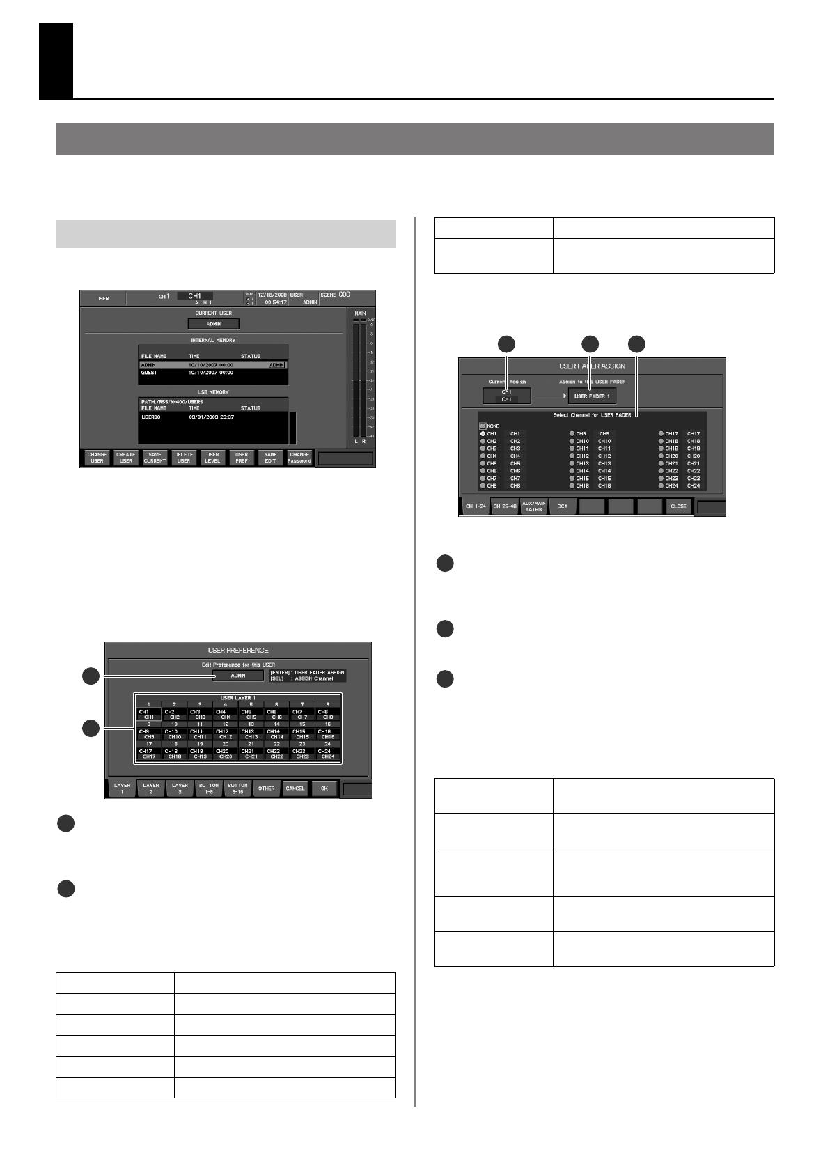
In the USER section, press [DISP].
fig.ScrUser.eps
The USER screen will appear.
2.
From the user list, select the desired user.
3.
Press [F6 (USER PREF)].
The USER PREFERENCE popup will appear.
4.
Press the button from [F1 (LAYER 1)] through [F3 (LAYER
3)] that matches the user layer whose settings you want
to make, displaying the LAYER tab.
ig.ScrUserFaderGuide.eps
Applicable user indication
This indicates the user settings to which the USER PREFERENCE
popup applies.
User fader assign 1–12
This area indicates the channels that are assigned to user faders 1–12
In the USER PREFERENCE popup, the function buttons perform the
following operations.
5.
Move the cursor to the desired user fader assignment,
and press [ENTER].
fig.ScrUserFdrAsgn.eps
The USER FADER ASSIGN popup will appear.
Applicable user fader
This indicates the user fader to which the USER FADER ASSIGN setting
applies.
Current assignment
This indicates the channel that is currently assigned to the user fader.
Assignment channel select buttons
Here you can select the channel that will be assigned to the user
fader. The selected channel will be assigned to the user fader.
In the USER FADER ASSIGN popup, the function buttons perform the
following operations.
6.
Use [F1 (CH 1–24)], [F2 (CH 25–48)], [F3 (AUX/MATRIX)],
or [F4 (DCA)] to access the tab that contains the desired
channel.
7.
Move the cursor to the desired channel, and press
[ENTER] to select it.
Editing the user fader assignments
[F1 (LAYER 1)] Accesses the LAYER 1 tab.
[F2 (LAYER 2)] Accesses the LAYER 2 tab.
[F3 (LAYER 3)] Accesses the LAYER 3 tab.
[F4 (BUTTON 1-8)] Accesses the BUTTON 1–8 tab.
[F5 (BUTTON 9–16)] Accesses the BUTTON 9–16 tab.
[F6 (OTHER)] Accesses the OTHER tab.
1
2
1
2
[F7 (CANCEL)]
Cancels the changes and closes the popup.
[F8 (OK)] Confirms the changes and closes the pop-
up.
[F1 (CH 1–24)] Displays CH1–CH24 as the assignment
channel select buttons.
[F2 (CH 25–48)] Displays CH25–CH48 as the assignment
channel select buttons.
[F3 (AUX/MAIN/
MATRIX)]
Displays AUX1–AUX16, MATRIX1–
MATRIX8, MAIN C as the assignment
channel select buttons.
[F4 (DCA)] Displays DCA1–DCA8 as the assignment
channel select buttons.
[F8 (CLOSE)] Confirms the changes and closes the pop-
up.
3
4
5
3
4
5
M-400_v21Added_e.book 14 ページ 2010年1月28日 木曜日 午前8時56分
15
New Functionality for User Faders
8.
Press [F8 (CLOSE)] to finalize the changes and close the
USER FADER ASSIGN popup.
9.
Press [F8 (OK)] to finalize the changes and close the USER
PREFERENCE popup.
If you press [F7 (CANCEL)], the changes will be cancelled and the
USER PREFERENCE popup will close.
As an alternative to pressing [ENTER] in step 5, you can use the value
dial to edit the user fader assignment.
fig.LayerSectGuide.eps
1.
Press the USER layer button in the LAYER section.
The USER layer button lits, and the USER layer mode is activated.
2.
Press the layer button that corresponds to the user layer
you want to switch to.
The selected layer button lits.
The layer buttons correspond to the user layers as shown below.
3.
Press the USER layer button.
The USER layer mode is switched off.
Switching to the user layer
AUX/DCA layer button
User layer 3
CH25-48 layer button User layer 2
CH1-24 layer button User layer 1
USER layer button
User Layer 3
User Layer 2
User Layer 1
M-400_v21Added_e.book 15 ページ 2010年1月28日 木曜日 午前8時56分
16
New Functionality for the Input Channels
A channel mute option has been added.
You can select whether to mute out AUX SENDs and DIRECT OUTs when muting CH1–48.
Sends from POST FADER are always muted by the channel muting, regardless of the channel mute option settings.
New Functionality for the Input Channels
PRE EQ PRE FADER POST FADER
MUTE FADER
CH 1–48
4BAND
EQ
PA N
PRE EQ
SW SEND
SOLO
PRE EQ
AFL(R)
PFL(R)
AFL(L)
PFL(L)
SW SEND
AFL SW
PRE EQ
AUX SEND 1–16
PRE FADER
POST FADER
PA N
PRE FADER
POST FADER
PRE FADER
POST FADER
TO MAIRIX 1–8,
TO OUTPUT PATCHBAY
AUX
LINK
DIRECT OUT
POINT
MUTE
MUTE
1.
Press [SYSTEM] to access the SYSTEM screen.
fig.System.eps
CH-MUTE OPTION selection buttons
These buttons make the settings for the channel mute options.
Mutes AUX SENDS
If this is checked, muting input channel also mutes AUX SENDs.
Mutes DIRECT OUTS
If this is checked, muting input channel also mutes DIRECT OUTs.
2.
Use the CH-MUTE OPTION selection buttons to make the
settings for the channel mute options.
The settings you make here are applied to all input channels.
Setting the Channel Mute Options
1
1
1PS
M-400_v21Added_e.book 16 ページ 2010年1月28日 木曜日 午前8時56分
  • Page 1 1
  • Page 2 2
  • Page 3 3
  • Page 4 4
  • Page 5 5
  • Page 6 6
  • Page 7 7
  • Page 8 8
  • Page 9 9
  • Page 10 10
  • Page 11 11
  • Page 12 12
  • Page 13 13
  • Page 14 14
  • Page 15 15
  • Page 16 16

Roland M-400 Owner's manual

Category
Audio equalizers
Type
Owner's manual

Roland M-400 is a versatile digital mixer that offers a wide range of features for both live sound and recording applications. With its 40 input channels, 24 mix buses, and 8 matrix outputs, the M-400 provides ample headroom for even the most complex productions. The built-in effects engine includes a variety of reverbs, delays, and modulation effects, while the GEQ and compressor/limiter on each channel provide precise sound shaping capabilities. The M-400 also features a built-in USB audio interface, making it easy to record and playback audio directly to and from a computer.

Ask a question and I''ll find the answer in the document

Finding information in a document is now easier with AI