Page is loading ...

The Shure Model M64A Stereo Preamplifier provides
the proper input and output impedances, voltage gain
and equalization necessary to operate magnetic phono
cartridges and tape playback heads with audio ampli-
fiers having no equalization. A low-noise and
low-
distortion device, the M64A permits further signal pro-
cessing without appreciable degradation in signal-to-
noise ratio. In addition, the preamp can be used without
equalization for a microphone input or as a buffer
amplifier.
222
HARTREY AVENUE
SIIUmB
EvANsToN. ILLINOIS
60202-3696
U.S.A.
ME
SOUND
OF
ME R)(XEYIONALl@
UK)RLWIM
MICROPHONES
AND
ELECTRONIC
COMPONENTS
A
Typical Applications
Permits turntable to be used with PA mixers and
amplifiers without phono inputs
DATA SHEET
MODEL M64A
STEREO PREAMPLIFIER
L
Converting stereo record pickup systems from
ceramic to magnetic cartridges
Microphone preamplifier
Low-gain buffer amplifier (where long cable lengths
are extended to a preamp input)
The
M64A has a single three-position slide switch for
selecting Phono, Tape or Flat frequency compensation.
The Phono position provides the standard RIAA
equalization for phonograph records. In this mode,
magnetic phono cartridges can operate into auxiliary
level inputs, inputs without
RIAA equalization, or
ceramic phono cartridge inputs. The Tape position pro-
vides playback heads on tape recorders with standard
7-112 ips NARTB equalization. In the Flat position, the
M64A can be used as a flat-response microphone
preamplifier, or as
a buffer (isolation) amplifier for
magnetic phono cartridges when long cable lengths or
switching systems are necessary between the turntable
and main equalized amplifier (note that the low-level
outputs should be used when operating the
M64A as a
buffer amplifier).
The
M64A's inputs and outputs are standard phono
pin jacks. Both high- and low-level outputs are provided,
so that the
M64A can be connected to either high-level
auxiliary inputs or low-level microphone inputs (or
equalized phono or tape head inputs in buffering appli-
cations). A grounding screw is provided for hum pickup
reduction.
The
M64A as supplied operates on 120 Vac, 50160 Hz.
An internal selector switch (qualified service personnel
only) permits operation from 240
Vac, 50160 Hz sources.
The unit can also be modified for balanced line output.
The
M64A is listed by Underwriters Laboratories, Inc.
SPECIFICATIONS
Gain
(Measured at 1 kHz; input through 680 ohms; output
terminated in 47 kilohms)
Switch
High-Level Low-Level
Position Output
Output
Phono
+
34.5 dB +11 dB
Flat
+
27.5 dB
+
4 dB
Tape
+37 dB
+
13.5 dB
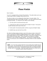
Frequency Response
Phono:
+
2 dB of Standard RIAA curve from 40 Hz to
15 kHz
Flat:
20 Hz to 20 kHz,
+2 dB
Tape:
*
2 dB of 7-1/2 ips NARTB curve from 50
Hz
to
15
kHz
60
$
Y2
0
40
-
30
20
20
100 1000
FREQUENCY
IN
HERTZ
10,000 20.000
TYPICAL FREQUENCY RESPONSE
FIGURE
1
Total Harmonic Distortion
Less than 1% with 2V output at 1 kHz in all switch
positions. Phono position only: less than
l0/o
at 30
Hz with 2V output.
Clipping Level
(at 1 kHz)
Phono: 100
mV minimum
Flat: 250
mV minimum
Tape: 80
mV minimum
Channel Separation
(at 1 kHz)
50 dB or more
Channel Balance
(at 1 kHz)
Within 2 dB
Hum and Noise
(20 Hz to 20 kHz)
Phono:
Better than 71 dB below 10
mV input
Flat:
Better than 64 dB below 10
mV input
Copyright
1989.
Shure Brothers
Inc.
27A8086
(IF)

OPERATION
lnput lmpedance (at 1 kHz)
Resistance: 50
kilohms
Capacitance: 160 picofarads
Output Impedance (at 1 kHz)
High Level: Less than 2000 ohms (minimum recom-
mended load is 22,000 ohms)
Low Level: 600 ohms (any load on Low Level output
will not affect input clipping level)
Power Consumption
5 watts
Operating Voltage
120 or 240 volts ac
+
1O0/0, 50160 Hz (internally selec-
table)
Temperature Range
Operating:
-7" to 57" C (20" to 135"
F)
Storage: -29" to 71
"
C (-20" to 160"
F)
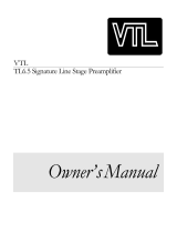
Dimensions
See Figure 2
Net Weight
986 grams (1
Ib 2-112 oz)
144mm 104mm
r(5-9/16
IN.
)
1
(4-3/32 IN.I~
OVERALL DIMENSIONS
FIGURE
2
INSTALLATION
To reduce the risk of fire or electric shock, do
not expose this appliance to rain or extreme
moisture.
The
M64A can be operated on any flat surface, or
(with adequate space) be mounted to an amplifier
chassis or cabinet using screws through the
M64A's
mounting flanges. The unit can be mounted in any posi-
tion for normal operation, but for best results, it should
be located away from motors, lighting dimmers, or other
hum-producing power sources and away from intense
heat sources.
Should hum be encountered in a sound system or
installation, one or more of the equipment power plugs
may be reversed to reduce hum. If the turntable has a
grounding lead, this wire can be connected to the
M64A
Ground screw to reduce hum pickup.
WARNING
Use of the M64A with power amplifiers of the
transformerless (ac-dc) type may result in a
shock hazard. A suitable power line isolation
transformer should be used with such equip-
ment.
1. Set the selector switch to the desired function
(Phono, Flat or Tape). This automatically selects the
proper equalization (frequency response) for both
channels.
2. For the equalized Phono
(RIAA) or Tape (NARTB) posi-
tions, connect the signal leads from the phono car-
tridge or tape head to the
M64A jacks marked Chan-
nel
1
lnput and Channel 2 Input. Note that the Flat
position can be used for phono cartridge or tape
head buffering applications in which the
M64A out-
put is connected to an equalized amplifier input.
3. For the Flat position using two high-impedance
microphones, connect each microphone cable to
one of the
M64A lnput connectors. If a single high-
impedance microphone is used, connect it to either
lnput connector. NOTE: If low-impedance
microphones are to be used, a suitable line match-
ing transformer such as Shure's A95 Series should be
used.
4. Refer to the phono cartridge, tape head or
microphone data sheet
for details on connections,
phasing and grounding.
5. Connect the Channel 1 and Channel 2 Output jacks
(High or Low Level) to the corresponding input jacks
of the power amplifier, preamplifier, tape recorder or
mixer. The High Level outputs can be connected to
high-level auxiliary inputs, and the Low Level out-
puts can be connected to low-level microphone in-
puts (or equalized phono or tape head inputs in buf-
fering applications).
6. If grounding is necessary, the associated equipment
ground lead can be attached to the
M64A Ground
screw.
7.
Insert the M64A power line cord into a proper power
outlet (120
Vac +lo%, 50160 Hz), preferably one
controlled by the power amplifier's on-off switch.
Make certain the
M64A Power switch is turned on if
the unit is to be remotely turned on and off.
SERVICE
WARNING
Voltages in this equipment are hazardous to life.
Refer servicing to qualified service personnel.
Balanced Line Output
For professional low-impedance balanced-line use
such as broadcast systems or recording consoles, an
external line matching transformer such as Shure's A95
Series can be added to each
M64A High Level output.
The resultant output level is approximately -32
dBm. If
2

a higher output is required (-20 dBm), the following
modification can be made to increase the output level
by approximately
12 dB.
1.
Unplug the
ac
power line cord.
2. Remove the two screws securing the top cover and
remove the top cover.
3.
Locate the vertically mounted main printed circuit
attached to the front panel. Resistors R13 and R14
(1 k, 114W, 10%) are soldered to the foil side of the
board.
4. Carefully wrap and solder the leads of 330-ohm,
114W resistors across (in parallel with) the leads of
R13 and R14. Use a low-wattage soldering iron and
avoid contact with the circuit board or other com-
ponents.
5. Replace and secure the top cover.
240
Vac Operation
The M64A as supplied will operate from a 120 Vac
10%, 50160
Hz
power source. For operation from a 240
Vac
k
lo%, 50160
Hz
power source, perform the follow-
ing steps.
1. Unplug the ac line cord and remove the two black
self-tapping screws securing the top cover.
2. Remove the top cover.
3.
Locate the voltage selector switch and move it to
the 240 position.
4.
Replace the ac line cord and plug (if necessary) with
one designed for the 240
Vac source. If the M64A
is to be used outside the U.S. and Canada, local
regulations may require replacing the line cord with
one having wire insulation colors as follows:
"Live" or
"Hot" Neutral Earth or Ground
NOTE: The above modification decreases the input
clipping level to approximately 25
mV. This means that
U.S., Canada Black
White Green
Europe
Brown
Blue
GreenlYellow
if
high-Out~ut cartridges
Or
very
modulated
5.
Replace the top cover and mark the rear panel to
records are used, the M64A may tend to clip on loud
reflect the new operating voltage.
Dassaaes. If a gain increase of less than 12 dB is
desire& use the following resistor values instead of 330
ohms.
Gain Resistor
3
dB 2.2k
6 dB lk
9
dB 560 ohms
PRINTED CIRCUIT BOARDS
COMPONENT SIDE
M-64
TOP
SILK

REPLACEMENT PARTS LIST
REFERENCE
DESCRIPTION
C 1
C2-C3
C8-C9
C14-C15
C16-C17
C24
C26
Dl -D2
J
1
J
2
Q1 -Q2
Q3-Q4
R1
R3-R4
R5-R6
R13-R14
S 1
S2
S3
TI
W1
DESCRIPTION
Capacitor, Electrolytic, 22 pF, 35V
Capacitor, Electrolytic, 4.7
pF,
25V
Capacitor, Electrolytic, 100
pF, 25V
Capacitor, Electrolytic, 4.7
pF, 35V
Capacitor, Electrolytic, 47
pF, 16V
Capacitor, Electrolytic, 220
pF, 50V
Capacitor, Electrolytic, 470 pF, 50V
Diode, Silicon Rectifier,
100V, 112A
Connector Assembly, Input
Connector Assembly, Output
Transistor, Silicon, NPN
Transistor, Silicon, PNP
Resistor, Metal Oxide,
1.3k, 112W
Resistor, Metal Film,
68k, 1/4W, 1%
Resistor, Metal Film,
180k, 114W, 1%
Resistor, Metal Film, lk,
114W, 1%
Switch, Slide,
DP3T, Equalizer
Switch, Slide, DPDT, Power
Switch, Slide, DPDT, Voltage Selector
Transformer, Power
Line Cord, Ac, 3-Conductor, 2.1 m (7
ft)
I
COMMERCIAL ALTERNATE
Sprague 503D226F035MB
Nichicon UKBl E4R7KAA
Nichicon UKBl H100KAA
Sprague 503D475F035KA
Mallory VTL-47S16
Mal lory VTL-220S50
Mallory VTL-470S50
Shure RKC21*, Motorola 1 N4002
None
None
None*
None*
RCA 830047
TRWllRC TO-60
TRWllRC TO-60
TRWllRC TO-60
None
None
Switchcraft
46206LFR
None
Shure
95A8015
Parts listed as "None" should be ordered from Shure Brothers Inc. listing product model number, reference designation, and part description.
'Supplied in multiples of four only.
"When replacing transistors
Q1-Q4,
pay close attention to lead configurations.
CIRCUIT DIAGRAM
A5011-11-1
/