Page is loading ...

40
AMP
1
DC
PHASE
Art # A-09347_AE
PLASMA CUTTING SYSTEM
42
CUTMASTER
™
Rev. AA Date: October 15, 2010 Manual # 0-5141
Operating Features:
Operating Manual

WE APPRECIATE YOUR BUSINESS!
Congratulations on your new Thermal Dynamics product. We
are proud to have you as our customer and will strive to provide
you with the best service and reliability in the industry. This
product is backed by our extensive warranty and world-wide
service network. To locate your nearest distributor or service
provider visit us on the web at www.cigweld.com.au (Asia
Pacific) www.thermal-dynamics.com (Americas and Europe).
This Operating Manual has been designed to instruct you on the
correct use and operation of your Thermal Dynamics product. Your
satisfaction with this product and its safe operation is our ultimate
concern. Therefore please take the time to read the entire manual,
especially the Safety Precautions. They will help you to avoid
potential hazards that may exist when working with this product.
YOU ARE IN GOOD COMPANY!
The Brand of Choice for Contractors and Fabricators Worldwide.
Thermal Dynamics is a Global Brand of manual and automation
Plasma Cutting Products for Thermadyne Industries Inc.
We distinguish ourselves from our competition through market-
leading, dependable products that have stood the test of time.
We pride ourselves on technical innovation, competitive prices,
excellent delivery, superior customer service and technical support,
together with excellence in sales and marketing expertise.
Above all, we are committed to developing technologically
advanced products to achieve a safer working environment within
the welding industry.

!
WARNINGS
Read and understand this entire Manual and your employer’s safety practices before installing, operat-
ing, or servicing the equipment.
While the information contained in this Manual represents the Manufacturer's best judgement, the
Manufacturer assumes no liability for its use.
Plasma Cutting Power Supply
CutMaster™ 42
SL40 Torch™
Operating Manual Number 0-5141
Published by:
Thermal Dynamics Corporation
82 Benning Street
West Lebanon, New Hampshire, USA 03784
(603) 298-5711
www.thermal-dynamics.com
Copyright 2010 by
Thermadyne Corporation
All rights reserved.
Reproduction of this work, in whole or in part, without written permission of the publisher is
prohibited.
The publisher does not assume and hereby disclaims any liability to any party for any loss or
damage caused by any error or omission in this Manual, whether such error results from negli-
gence, accident, or any other cause.
Printed in the United States of America
Publication Date: October 15, 2010
Record the following information for Warranty purposes:
Where Purchased:_______________________________ __________________
Purchase Date:__________________________________ __________________
Power Supply Serial #:___________________________ ___________________
Torch Serial #:___________________________________ _________________
i

TABLE OF CONTENTS
SECTION 1:GENERAL INFORMATION ........................................................................................................ 1-1
1.01 Notes, Cautions and Warnings ................................................................................. 1-1
1.02 Important Safety Precautions ................................................................................... 1-1
1.03 Publications .............................................................................................................. 1-3
1.04 Note, Attention et Avertissement ..............................................................................1-4
1.05 Precautions De Securite Importantes ....................................................................... 1-4
1.06 Documents De Reference ......................................................................................... 1-6
1.07 Declaration of Conformity......................................................................................... 1-7
1.08 Statement of Warranty ............................................................................................. 1-8
SECTION 2 SYSTEM:INTRODUCTION ...................................................................................................... 2-1
2.01 Working Principle .....................................................................................................
2-1
2.02 Power Supply Specifications ....................................................................................2-1
2.03 Input Wiring Specifications ...................................................................................... 2-2
2.04 Power Supply Features ............................................................................................. 2-3
SECTION 2 TORCH:INTRODUCTION ...................................................................................................... 2T-1
2T.01 Scope of Manual
..................................................................................................... 2T-1
2T.02 Specifications ........................................................................................................ 2T-1
2T.03 Introduction to Plasma ........................................................................................... 2T-2
SECTION 3 SYSTEM:INSTALLATION ........................................................................................................ 3-1
3.01 Unpacking ................................................................................................................ 3-1
3.02 Lifting Options .......................................................................................................... 3-1
3.03 Primary Input Power Connections ............................................................................ 3-2
3.04 Air Supply Connections ............................................................................................3-2
SECTION 4 SYSTEM:OPERATION .............................................................................................................. 4-1
4.01 Control Panel ............................................................................................................
4-1
4.02 Preparations for Operating ....................................................................................... 4-2
4.03 Sequence of Operation ............................................................................................. 4-4
4.04 Cut Quality ................................................................................................................ 4-6
4.05 General Cutting Information ..................................................................................... 4-7
SECTION 5 SYSTEM:SERVICE .................................................................................................................. 5-1
5.01 General Maintenance ................................................................................................ 5-1
5.02 Basic Troubleshooting Guide .................................................................................... 5-2
SECTION 5 TORCH:SERVICE
...................................................................................................................
5T-1
5T.01 General Maintenance ..............................................................................................
5T-1
5T.02 Inspection and Replacement of Consumable Torch Parts ....................................... 5T-1
SECTION 6:PARTS LISTS .......................................................................................................................... 6-1
6.01 Introduction ..............................................................................................................
6-1
6.02 Power Supply Replacement Parts ............................................................................ 6-2
APPENDIX 1:CIRCUIT DIAGRAM .............................................................................................................A-1
GLOBAL CUSTOMER SERVICE CONTACT INFORMATION ............................................................ Rear Cover

cutmaster 42
Manual 0-5141 1-1 GENERAL INFORMATION
SECTION 1:
GENERAL INFORMATION
1.01 Notes, Cautions and Warnings
Throughout this manual, notes, cautions, and warnings are used to
highlight important information. These highlights are categorized as
follows:
NOTE
An operation, procedure, or background information
which requires additional emphasis or is helpful in ef-
ficient operation of the system.
CAUTION
A procedure which, if not properly followed, may cause
damage to the equipment.
!
WARNING
A procedure which, if not properly followed, may cause
injury to the operator or others in the operating area.
1.02 Important Safety Precautions
!
WARNING
OPERATION AND MAINTENANCE OF PLASMA ARC
EQUIPMENT CAN BE DANGEROUS AND HAZARDOUS
TO YOUR HEALTH.
Plasma arc cutting produces intense electric and magnet-
ic emissions that may interfere with the proper function
of cardiac pacemakers, hearing aids, or other electronic
health equipment. Persons who work near plasma arc
cutting applications should consult their medical health
professional and the manufacturer of the health equip-
ment to determine whether a hazard exists.
To prevent possible injury, read, understand and follow
all warnings, safety precautions and instructions before
using the equipment. Call 1-603-298-5711 or your local
distributor if you have any questions.
GASES AND FUMES
Gases and fumes produced during the plasma cutting process can be
dangerous and hazardous to your health.
• Keep all fumes and gases from the breathing area. Keep your
head out of the welding fume plume.
• Use an air-supplied respirator if ventilation is not adequate to
remove all fumes and gases.
• The kinds of fumes and gases from the plasma arc depend on
the kind of metal being used, coatings on the metal, and the
different processes. You must be very careful when cutting
or welding any metals which may contain one or more of the
following:
Antimony Chromium Mercury
Arsenic Cobalt Nickel
Barium Copper Selenium
Beryllium Lead Silver
Cadmium Manganese Vanadium
• Always read the Material Safety Data Sheets (MSDS) that should
be supplied with the material you are using. These MSDSs
will give you the information regarding the kind and amount of
fumes and gases that may be dangerous to your health.
• For information on how to test for fumes and gases in your
workplace, refer to item 1 in Subsection 1.03, Publications in
this manual.
• Use special equipment, such as water or down draft cutting
tables, to capture fumes and gases.
• Do not use the plasma torch in an area where combustible or
explosive gases or materials are located.
• Phosgene, a toxic gas, is generated from the vapors of chlo
-
rinated solvents and cleansers. Remove all sources of these
vapors.
• This product, when used for welding or cutting, produces
fumes or gases which contain chemicals known to the State
of California to cause birth defects and, in some cases, cancer.
(California Health & Safety Code Sec. 25249.5 et seq.)
ELECTRIC SHOCK
Electric Shock can injure or kill. The plasma arc process uses and
produces high voltage electrical energy. This electric energy can cause
severe or fatal shock to the operator or others in the workplace.
• Never touch any parts that are electrically “live” or “hot.”
• Wear dry gloves and clothing. Insulate yourself from the work
piece or other parts of the welding circuit.
• Repair or replace all worn or damaged parts.
• Extra care must be taken when the workplace is moist or
damp.
• Install and maintain equipment according to NEC code, refer to
item 9 in Subsection 1.03, Publications.
• Disconnect power source before performing any service or
repairs.
• Read and follow all the instructions in the Operating Manual.
FIRE AND EXPLOSION
Fire and explosion can be caused by hot slag, sparks, or the plasma
arc.
• Be sure there is no combustible or flammable material in the
workplace. Any material that cannot be removed must be
protected.
• Ventilate all flammable or explosive vapors from the work
-
place.
• Do not cut or weld on containers that may have held combus
-
tibles.

cutmaster 42
GENERAL INFORMATION 1-2 Manual 0-5141
• Provide a fire watch when working in an area where fire hazards
may exist.
• Hydrogen gas may be formed and trapped under aluminum
workpieces when they are cut underwater or while using a water
table. DO NOT cut aluminum alloys underwater or on a water
table unless the hydrogen gas can be eliminated or dissipated.
Trapped hydrogen gas that is ignited will cause an explosion.
NOISE
Noise can cause permanent hearing loss. Plasma arc processes can
cause noise levels to exceed safe limits. You must protect your ears
from loud noise to prevent permanent loss of hearing.
• To protect your hearing from loud noise, wear protective ear
plugs and/or ear muffs. Protect others in the workplace.
• Noise levels should be measured to be sure the decibels (sound)
do not exceed safe levels.
• For information on how to test for noise, see item 1 in Subsec
-
tion 1.03, Publications, in this manual.
PLASMA ARC RAYS
Plasma Arc Rays can injure your eyes and burn your skin. The plasma
arc process produces very bright ultra violet and infrared light. These
arc rays will damage your eyes and burn your skin if you are not
properly protected.
• To protect your eyes, always wear a welding helmet or shield.
Also always wear safety glasses with side shields, goggles or
other protective eye wear.
• Wear welding gloves and suitable clothing to protect your skin
from the arc rays and sparks.
• Keep helmet and safety glasses in good condition. Replace
lenses when cracked, chipped or dirty.
• Protect others in the work area from the arc rays. Use protective
booths, screens or shields.
• Use the shade of lens as suggested in the following per ANSI/
ASC Z49.1:
Minimum Protective Suggested
Arc Current Shade No. Shade No.
Less Than 300* 8 9
300 - 400* 9 12
400 - 800* 10 14
*These values apply where the actual arc is clearly
seen. Experience has shown that lighter filters may
be used when the arc is hidden by the workpiece.
LEAD WARNING
This product contains chemicals, including lead, or otherwise produces
chemicals known to the State of California to cause cancer, birth defects
and other reproductive harm. Wash hands after handling. (California
Health & Safety Code § 25249.5 et seq.)
Eye protection filter shade selector for welding or cutting
(goggles or helmet), from AWS A6.2-73.
Welding or Cutting
Operation
Electrode Size
Metal Thickness
Filter
Shade
Welding or Cutting
Operation
Electrode Size
Metal Thickness
Filter
Shade
Torch soldering 2
Gas metal-arc
welding (MIG)
Torch brazing 3 or 4 Non-ferrous base metal All 11
Oxygen Cutting Non-ferrous base metal All 12
Light Under 1 in., 25 mm 3 or 4 Gas tungsten arc welding All 12
Medium 1 to 6 in., 25-150 mm 4 or 5 (TIG) All 12
Heavy Over 6 in., 150 mm 5 or 6 Atomic hydrogen welding All 12
Gas welding Carbon arc welding All 12
Light Under 1/8 in., 3 mm 4 or 5 Plasma arc welding
Medium 1/8 to 1/2 in., 3-12 mm 5 or 6 Carbon arc air gouging
Heavy Over 1/2 in., 12 mm 6 or 8 Light 12
Shielded metal-arc
welding
(stick) electrodes
Under 5/32 in., 4 mm 10 Heavy 14
5/32 to 1/4 in.,
4 to 6.4 mm
12 Plasma arc cutting
Over 1/4 in., 6.4 mm 14 Light Under 300 Amp 9
Medium 300 to 400 Amp 12
Heavy Over 400 Amp 14
Table 1-1

cutmaster 42
Manual 0-5141 1-3 GENERAL INFORMATION
1.03 Publications
Refer to the following standards or their latest revisions for more
information:
1.
OSHA, SAFETY AND HEALTH STANDARDS, 29CFR 1910, obtain-
able from the Superintendent of Documents, U.S. Government
Printing Office, Washington, D.C. 20402
2. ANSI Standard Z49.1, SAFETY IN WELDING AND CUTTING, ob
-
tainable from the American Welding Society, 550 N.W. LeJeune
Rd, Miami, FL 33126
3. NIOSH, SAFETY AND HEALTH IN ARC WELDING AND GAS
WELDING AND CUTTING, obtainable from the Superintendent of
Documents, U.S. Government Printing Office, Washington, D.C.
20402
4. ANSI Standard Z87.1, SAFE PRACTICES FOR OCCUPATION AND
EDUCATIONAL EYE AND FACE PROTECTION, obtainable from
American National Standards Institute, 1430 Broadway, New York,
NY 10018
5. ANSI Standard Z41.1, STANDARD FOR MEN’S SAFETY-TOE
FOOTWEAR, obtainable from the American National Standards
Institute, 1430 Broadway, New York, NY 10018
6. ANSI Standard Z49.2,
FIRE PREVENTION IN THE USE OF CUTTING
AND WELDING PROCESSES, obtainable from American National
Standards Institute, 1430 Broadway, New York, NY 10018
7. AWS Standard A6.0,
WELDING AND CUTTING CONTAINERS
WHICH HAVE HELD COMBUSTIBLES, obtainable from American
Welding Society, 550 N.W. LeJeune Rd, Miami, FL 33126
8. NFPA Standard 51,
OXYGEN-FUEL GAS SYSTEMS FOR WELD-
ING, CUTTING AND ALLIED PROCESSES, obtainable from the
National Fire Protection Association, Batterymarch Park, Quincy,
MA 02269
9. NFPA Standard 70, NATIONAL ELECTRICAL CODE, obtainable
from the National Fire Protection Association, Batterymarch Park,
Quincy, MA 02269
10. NFPA Standard 51B, CUTTING AND WELDING PROCESSES,
obtainable from the National Fire Protection Association, Bat-
terymarch Park, Quincy, MA 02269
11. CGA Pamphlet P-1, SAFE HANDLING OF COMPRESSED GASES
IN CYLINDERS, obtainable from the Compressed Gas Association,
1235 Jefferson Davis Highway, Suite 501, Arlington, VA 22202
12. CSA Standard W117.2, CODE FOR SAFETY IN WELDING AND
CUTTING, obtainable from the Canadian Standards Association,
Standards Sales, 178 Rexdale Boulevard, Rexdale, Ontario, Canada
M9W 1R3
13. NWSA booklet, WELDING SAFETY BIBLIOGRAPHY obtainable
from the National Welding Supply Association, 1900 Arch Street,
Philadelphia, PA 19103
14. American Welding Society Standard AWSF4.1, RECOMMENDED
SAFE PRACTICES FOR THE PREPARATION FOR WELDING AND
CUTTING OF CONTAINERS AND PIPING THAT HAVE HELD HAZ-
ARDOUS SUBSTANCES, obtainable from the American Welding
Society, 550 N.W. LeJeune Rd, Miami, FL 33126
15. ANSI Standard Z88.2, PRACTICE FOR RESPIRATORY PROTEC
-
TION, obtainable from American National Standards Institute, 1430
Broadway, New York, NY 10018

cutmaster 42
GENERAL INFORMATION 1-6 Manual 0-5141
1.06 Documents De Reference
Consultez les normes suivantes ou les révisions les plus récentes
ayant été faites à celles-ci pour de plus amples renseignements :
1. OS HA, NOR MES DE SÉ C URI TÉ D U T RAVAI L E T D E
PROTECTION DE LA SANTÉ, 29CFR 1910, disponible auprès du
Superintendent of Documents, U.S. Government Printing Office,
Washington, D.C. 20402
2. Norme ANSI Z49.1, LA SÉCURITÉ DES OPÉRATIONS DE COUPE
ET DE SOUDAGE, disponible auprès de la Société Américaine de
Soudage (American Welding Society), 550 N.W. LeJeune Rd.,
Miami, FL 33126
3. NIOSH, LA SÉCURITÉ ET LA SANTÉ LORS DES OPÉRATIONS
DE COUPE ET DE SOUDAGE À L’ARC ET AU GAZ, disponible
auprès du Superintendent of Documents, U.S. Government
Printing Office, Washington, D.C. 20402
4. Norme ANSI Z87.1, PRATIQUES SURES POUR LA PROTECTION
DES YEUX ET DU VISAGE AU TRAVAIL ET DANS LES ECOLES,
disponible de l’Institut Américain des Normes Nationales
(American National Standards Institute), 1430 Broadway, New
York, NY 10018
5. Norme ANSI Z41.1, NORMES POUR LES CHAUSSURES
PROTECTRICES, disponible auprès de l’American National
Standards Institute, 1430 Broadway, New York, NY 10018
6. Norme ANSI Z49.2, PRÉVENTION DES INCENDIES LORS DE L’
EMPLOI DE PROCÉDÉS DE COUPE ET DE SOUDAGE, disponible
auprès de l’American National Standards Institute, 1430
Broadway, New York, NY 10018
7. Norme A6.0 de l’Association Américaine du Soudage (AWS), LE
SOUDAGE ET LA COUPE DE CONTENEURS AYANT RENFERMÉ
DES PRODUITS COMBUSTIBLES, disponible auprès de la
American Welding Society, 550 N.W. LeJeune Rd., Miami, FL
33126
8. Norme 51 de l’Association Américaine pour la Protection
contre les Incendies (NFPA), LES SYSTEMES À GAZ AVEC
ALIMENTATION EN OXYGENE POUR LE SOUDAGE, LA COUPE
ET LES PROCÉDÉS ASSOCIÉS, disponible auprès de la National
Fire Protection Association, Batterymarch Park, Quincy, MA
02269
9. Norme 70 de la NFPA, CODE ELECTRIQUE NATIONAL,
disponible auprès de la National Fire Protection Association,
Batterymarch Park, Quincy, MA 02269
10. Norme 51B de la NFPA, LES PROCÉDÉS DE COUPE ET DE
SOUDAGE, disponible auprès de la National Fire Protection
Association, Batterymarch Park, Quincy, MA 02269
11. Brochure GCA P-1, LA MANIPULATION SANS RISQUE DES
GAZ COMPRIMÉS EN CYLINDRES, disponible auprès de l’
Association des Gaz Comprimés (Compressed Gas Association),
1235 Jefferson Davis Highway, Suite 501, Arlington, VA 22202
12. Norme CSA W117.2, CODE DE SÉCURITÉ POUR LE SOUDAGE
ET LA COUPE, disponible auprès de l’Association des Normes
Canadiennes, Standards Sales, 178 Rexdale Boulevard, Rexdale,
Ontario, Canada, M9W 1R3
13. Livret NWSA, BIBLIOGRAPHIE SUR LA SÉCURITÉ DU SOUDAGE,
disponible auprès de l’Association Nationale de Fournitures de
Soudage (National Welding Supply Association), 1900 Arch
Street, Philadelphia, PA 19103
14. Norme AWSF4.1 de l’Association Américaine de Soudage,
RECOMMANDATIONS DE PRATIQUES SURES POUR LA
PRÉPARATION À LA COUPE ET AU SOUDAGE DE CONTENEURS
ET TUYAUX AYANT RENFERMÉ DES PRODUITS DANGEREUX
, disponible auprès de la American Welding Society, 550 N.W.
LeJeune Rd., Miami, FL 33126
15. No rme AN S I Z 8 8 . 2 , PRAT I Q U E S D E P RO TECT I O N
RESPIRATOIRE, disponible auprès de l’American National
Standards Institute, 1430 Broadway, New York, NY 10018

cutmaster 42
Manual 0-5141 1-7 GENERAL INFORMATION
1.07 Declaration of Conformity
Manufacturer: Thermadyne Company
Address: 82 Benning Street
West Lebanon, New Hampshire 03784
USA
The equipment described in this manual conforms to all applicable aspects and regulations of the ‘Low Voltage Directive’ (European Council Directive
73/23/EEC as amended by Council Directive 93/68/EEC) and to the National legislation for the enforcement of this Directive.
The equipment described in this manual conforms to all applicable aspects and regulations of the "EMC Directive" (European Council Directive
89/336/EEC) and to the National legislation for the enforcement of this Directive.
Serial numbers are unique with each individual piece of equipment and details description, parts used to manufacture a unit and date of manufacture.
National Standard and Technical Specifications
The product is designed and manufactured to a number of standards and technical requirements. Among them are:
* CSA (Canadian Standards Association) standard C22.2 number 60 for Arc welding equipment.
* UL (Underwriters Laboratory) rating 94VO flammability testing for all printed-circuit boards used.
* CENELEC EN50199 EMC Product Standard for Arc Welding Equipment.
* ISO/IEC 60974-1 (BS 638-PT10) (EN 60 974-1) (EN50192) (EN50078) applicable to plasma cutting equipment and associated accessories.
* AS60974.1 Arc Welding Equipment Welding Power Sources.
For environments with increased hazard of electrical shock, Power Supplies bearing the
S
mark conform to EN50192 when used in
conjunction with hand torches with exposed cutting tips, if equipped with properly installed standoff guides.
* Extensive product design verification is conducted at the manufacturing facility as part of the routine design and manufacturing process.
This is to ensure the product is safe, when used according to instructions in this manual and related industry standards, and performs as
specified. Rigorous testing is incorporated into the manufacturing process to ensure the manufactured product meets or exceeds all design
specifications.
Thermadyne has been manufacturing products for more than 30 years, and will continue to achieve excellence in our area of manufacture.
Manufacturers responsible representative in Europe: Steve Ward
Operations Director
Thermadyne Europe
Europa Building
Chorley N Industrial Park
Chorley, Lancashire,
England PR6 7BX

cutmaster 42
GENERAL INFORMATION 1-8 Manual 0-5141
1.08 Statement of Warranty
LIMITED WARRANTY: Subject to the terms and conditions established below, Thermadyne Company warrants to the original retail purchaser that new
Thermal Dynamics CUTMASTER
®
plasma cutting systems sold after the effective date of this warranty are free of defects in material and workmanship.
Should any failure to conform to this warranty appear within the applicable period stated below, Thermadyne Company shall, upon notification thereof and
substantiation that the product has been stored operated and maintained in accordance with Thermadyne’s specifications, instructions, recommendations
and recognized industry practice, correct such defects by suitable repair or replacement.
This warranty is exclusive and in lieu of any warranty of merchantability or fitness for a particular purpose.
Thermadyne will repair or replace, at its discretion, any warranted parts or components that fail due to defects in material or workmanship within the
time periods set out below. Thermadyne Company must be notified within 30 days of any failure, at which time Thermadyne Company will provide
instructions on the warranty procedures to be implemented.
Thermadyne Company will honor warranty claims submitted within the warranty periods listed below. All warranty periods begin on the date of sale
of the product to the original retail customer or 1 year after sale to an authorized Thermadyne Distributor.
LIMITED WARRANTY PERIOD
Product
Power Supply Components
(Parts and Labor)
Torch and Leads
(Parts and Labor)
CUTMASTER 42 4 Year 1 Year
This warranty does not apply to:
1. Consumable Parts, such as tips, electrodes, shield cups, o - rings, starter cartridges, gas distributors, fuses, filters.
2. Equipment that has been modified by an unauthorized party, improperly installed, improperly operated or misused based upon industry standards.
In the event of a claim under this warranty, the remedies shall be, at the discretion of Thermadyne Company:
1. Repair of the defective product.
2. Replacement of the defective product.
3. Reimbursement of reasonable costs of repair when authorized in advance by Thermadyne.
4. Payment of credit up to the purchase price less reasonable depreciation based on actual use.
These remedies may be authorized by Thermadyne and are FOB West Lebanon, NH or an authorized Thermadyne service station. Product returned
for service is at the owner’s expense and no reimbursement of travel or transportation is authorized.
LIMITATION OF LIABILITY: Thermadyne Company shall not under any circumstances be liable for special or consequential damages such as, but not
limited to, damage or loss of purchased or replacement goods or claims of customer of distributors (hereinafter “Purchaser”) for service interruption.
The remedies of the Purchaser set forth herein are exclusive and the liability of Thermadyne with respect to any contract, or anything done in
connection therewith such as the performance or breach thereof, or from the manufacture, sale, delivery, resale, or use of the goods covered by or
furnished by Thermadyne whether arising out of contract, negligence, strict tort, or under any warranty, or otherwise, shall not, except as expressly
provided herein, exceed the price of the goods upon which liability is based.
This warranty becomes invalid if replacement parts or accessories are used which may impair the safety or performance of any Thermadyne
product.
This warranty is invalid if the Thermal Dynamics product is sold by non - authorized persons.
Effective October 15, 2010

cutmaster 42
Manual 0-5141 2-1 INTRODUCTION
SECTION 2 SYSTEM:
INTRODUCTION
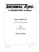
2.01 Working Principle
Rectifier
Inverter
Transformer
Rectifier
Reduce pressure, filter
Gas valve Cutting torch
Workpiece
Compressed air
Art # A-09204_AB
2.02 Power Supply Specifications
CUTMASTER 42 Power Supply Specifications
Input Power 120 VAC (+
-
10%), 1Phase, 50/60Hz
208-230 VAC (+
-
10%), 1Phase, 50/60Hz
Output Current 20 Amps @ 120VAC, 15A
20-27 Amps @ 120VAC, 20A
20-40 Amps @ 230VAC, 20A
CUTMASTER 42 Power Supply Duty Cycle (Note 1)
Ambient Temperature 104° F (40° C)
Duty Cycle 30% @ 120VAC, 40% @ 230VAC
Rated Current 27 Amps @ 120VAC, 40 Amps @ 230V
SL40 Torch Gas Requirements (see section 2T.03)
Notes
1. Duty Cycle is the percentage of time the system can be operated without overheating. Duty cycle is re-
duced if primary input voltage (AC) is low or the DC voltage is higher than shown in this chart.
2. Air supply must be free of oil, moisture, and other contaminants. Excessive oil and moisture may cause
double-arcing, rapid tip wear, or even complete torch failure. Contaminants may cause poor cutting perfor-
mance and rapid electrode wear. Optional filters provide increased filtering capabilities.
NOTE
IEC Rating is determined as specified by the International Electro-Technical Commission. These specifica-
tions include calculating an output voltage based upon power supply rated current. To facilitate comparison
between power supplies, all manufacturers use this output voltage to determine duty cycle.
TDC Rating is determined using an output voltage representative of actual output voltage during cutting
with a TDC torch. This voltage may be more or less than IEC voltage, depending upon choice of torch,
consumables, and actual cutting operation.

cutmaster 42
INTRODUCTION 2-2 Manual 0-5141
Art# A-09333_AC
26lb / 11.8kg
7" (177mm)
18.5" (469.9mm)
9" (228.6mm)
CUTMAST
ER
®
42
120V 15A
120V 20A
230V 20A
A
24
40
20
20
30
27
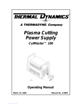
Figure 2-1 Power Supply Dimensions & Weight
NOTE
Weight includes torch & leads, input power cord, and work cable with clamp.
CAUTION
Provide clearance for proper air flow through the power supply. Operation without proper air flow will
inhibit proper cooling and reduce duty cycle.
2.03 Input Wiring Specifications
CUTMASTER 42 Input Power Requirements
Input Power Input Current Input Current Input Suggested Sizes (See Note)
Voltage Freq. (kVA) Max (Amps) Ieff (Amps) Fuse (Amps)
(Volts-AC) (Hz) 1-Ph 1-Ph 1-Ph 1-Ph
120 50/60 3.3 27.5 15 25
208 50/60 5.0 24 15.4 23
230 50/60 5.0 21.4 13.5 20
240 50/60 5.0 20.8 13 20
Line Voltages with Suggested Circuit Protection
Motor start fuses or thermal circuit breakers are recommended for this application. Check local requirements for your situation
in this regard.
NOTE
Refer to Local and National Codes or local authority having jurisdiction for proper wiring requirements.
Cable size is de-rated based on the Duty Cycle of the equipment.
The suggested sizes are based on flexible power cable with power plug installations.
Cable conductor temperature used is 167° F (75° C).

cutmaster 42
Manual 0-5141 2-3 INTRODUCTION
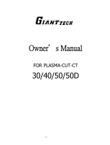
2.04 Power Supply Features
Air Inlet
Control Panel
Torch Lead
120/230 VAC Power Source
Work Cable and Clamp
Art # A-09334_AC
CUT
MAST
E
R
®
42
120V 15A
120V 20A
230V 20A
A
24
40
20
20
30
27
Art# A-09335
Air Inlet
On/Off
Switch
Power Cord

This Page left blank intentionally.

cutmaster 42
Manual 0-5141 2T-1 INTRODUCTION
SECTION 2TORCH:
INTRODUCTION
2T.01 Scope of Manual
This manual contains descriptions, operating instruc-
tions and maintenance procedures for the SL40 Plasma
Cutting Torch. Service of this equipment is restricted
to properly trained personnel; unqualified personnel are
strictly cautioned against attempting repairs or adjust-
ments not covered in this manual, at the risk of voiding
the Warranty. Read this manual thoroughly. A complete
understanding of the characteristics and capabilities of
this equipment will assure the dependable operation for
which it was designed.
2T.02 Specifications
A. Torch Configurations
1. Hand Torch, Model SL40
The hand torch head is at 75° to the torch handle.
The hand torches include a torch handle and torch
trigger assembly.
8.3" (210.82mm)
2.6"
(66.04mm)
3"
(66.04mm)
Radnor Version
.96" (24.38mm)
Art # A-09336
B. Torch Leads Lengths
Hand Torches are available as follows:
• 15 ft / 4.6 m.
C. Torch Parts
Starter Cartridge, Electrode, Tip, Shield Cup
D. Parts - In - Place (PIP)
Torch has built-in switch.
12 vdc circuit rating
E. Type Cooling
Combination of ambient air and gas stream through
torch.
F. Torch Ratings
SL40 Torch Ratings
Ambient
Temperature
104° F
40° C
Duty Cycle 100% @ 40 Amps @ 250 scfh
Maximum Current 40 Amps
Voltage (V
peak
) 500V
Arc Striking Voltage 500V
G. Current Ratings
SL40 Current Ratings
SL40 Torch & Leads
Up to 40 Amps, DC,
Straight Polarity
NOTE
Power Supply characteristics will determine
material thickness range.
H. Gas Requirements
SL40 Torch Gas Specications
Gas (Plasma and Secondary) Compressed Air
Minimum Input Pressure
85 psi
5.9 bar
Maximum Input Pressure 125 psi / 8.6 bar
Gas Flow
193 scfh
91 lpm
!
WARNING
This torch is not to be used with oxygen (O
2
).
This torch is not to be use with high frequency
starting systems.

CUTMASTER 42
INTRODUCTION 2T-2 Manual 0-5141
2T.03 Introduction to Plasma
A. Plasma Gas Flow
Plasma is a gas which has been heated to an extremely
high temperature and ionized so that it becomes electri-
cally conductive. The plasma arc cutting and gouging
processes use this plasma to transfer an electrical arc
to the workpiece. The metal to be cut or removed is
melted by the heat of the arc and then blown away.
While the goal of plasma arc cutting is separation of
the material, plasma arc gouging is used to remove
metals to a controlled depth and width.
In a Plasma Cutting Torch a cool gas enters Zone B,
where a arc between the electrode and the torch tip
heats and ionizes the gas. The main cutting arc then
transfers to the workpiece through the column of
plasma gas in Zone C.
By forcing the plasma gas and electric arc through a
small orifice, the torch delivers a high concentration
of heat to a small area. The stiff, constricted plasma
arc is shown in Zone C. Direct current (DC) straight
polarity is used for plasma cutting, as shown in the
illustration.
Zone A channels a secondary gas that cools the torch.
This gas also assists the high velocity plasma gas in
blowing the molten metal out of the cut allowing for a
fast, slag - free cut.
A-00002
Workpiece
Power
Supply
+
_
C
B
A
Typical Torch Head Detail
B. Gas Distribution
The single gas used is internally split into plasma and
secondary gases.
The plasma gas flows into the torch through the
negative lead, through the starter cartridge, around
the electrode, and out through the tip orifice.
The secondary gas flows down around the outside
of the torch starter cartridge, and out between the tip
and shield cup around the plasma arc.
C. Pilot Arc
When the torch is started a pilot arc is established
between the electrode and cutting tip. This pilot
arc creates a path for the main arc to transfer to the
work.
D. Main Cutting Arc
DC power is also used for the main cutting arc. The
negative output is connected to the torch electrode
through the torch lead. The positive output is con-
nected to the workpiece via the work cable and to the
torch through a pilot wire.
E. Parts - In - Place (PIP)
The torch includes a 'Parts - In - Place' (PIP) circuit.
When the shield cup is properly installed, it closes
a switch. The torch will not operate if this switch is
open.
Torch Trigge
r
PIP Switch
Shield Cup
To Control
Cable Wiring
Torch Switch
A-09595
Parts - In - Place Circuit Diagram for Hand Torch

cutmaster 42
Manual 0-5141 3-1 INSTALLATION
SECTION 3:
INSTALLATION
3.01 Unpacking
1. Use the packing lists to identify and account for each item.
A. Contents List
Description Quantity
CM42 Power source 1
10ft power input cable (installed) 1
120VAC Adapter Pigtail 15A 1
120VAC Adapter Pigtail 20A 1
Work cable and clamp (installed) 1
SL40 Torch (15ft(4.6m)) w/consumables 1
Carry case 1
40A Tip Drag 2
20A Tip Drag 2
40A Tip, Standoff 2
Electrode 2
Gloves 1
Cutting Glasses 1
2. Inspect each item for possible shipping damage. If damage is evident, contact your distributor and / or shipping
company before proceeding with the installation.
3. Record Power Supply and Torch model and serial numbers, purchase date and vendor name, in the information
block at the front of this manual.
3.02 Lifting Options
The Power Supply includes a handle for hand lifting only. Be sure unit is lifted and transported safely and securely.
WARNING
Do not touch live electrical parts.
Disconnect input power cord before moving unit.
FALLING EQUIPMENT can cause serious personal injury and can damage equipment.
HANDLE is not for mechanical lifting.
• Only persons of adequate physical strength should lift the unit.
• Lift unit by the handle, using two hands. Do not use straps for lifting.
• Use optional cart or similar device of adequate capacity to move unit.
• Place unit on a proper skid and secure in place before transporting with a fork lift or other vehicle.

cutmaster 42
INSTALLATION 3-2 Manual 0-5141
3.03 Primary Input Power Connections
Power Cords Included With Power Supply
Attached to the power supply is an input power cord with a 230 Volt 50 Amp NEMA 6-50P for plug. Supplied adapters
allow for connection of the power supply input cable plug for when using 120V input power.
Art# A-09432_AB
Figure 3-1 120VAC Adapter Pigtail
CAUTION
Check your power source for correct voltage before plugging in or connecting the unit. The primary power
source, fuse, and any extension cords used must conform to local electrical code and the recommended
circuit protection and wiring requirements as specified in Section 2.
Input Voltage (VAC) Rated Output
Amps (RMS) input at rated
output, 60 Hz, single-phase
kVA
120V, 15A Circuit 20A, 88V 20.4 2.5
120V, 20A Circuit 27A, 91V 28.5 3.5
120V, 30A Circuit 27A, 91V 28.5 3.5
208-230V, 20A Circuit 40A, 96V 23-21.4 4.8
3.04 Air Supply Connections
A. Connecting Air Supply to Unit
The connection is the same for compressed air or industrial compressed air in gas cylinders.
1. Connect the gas line to the compressed air inlet port at the appropriate pressure.

cutmaster 42
Manual 0-5141 3-3 INSTALLATION
Art# A-09337
Air Inlet
On/Off
Switch
Figure 3-2 Gas Connection to Compressed Air input
B. Using Industrial Compressed Air In Gas Cylinders
When using Industrial compressed air in gas cylinders as the gas supply:
1. Refer to the manufacturer’s specifications for installation and maintenance procedures for high pressure gas
regulators.
2. Examine the cylinder valves to be sure they are clean and free of oil, grease or any foreign material. Briefly open
each cylinder valve to blow out any dust which may be present.
3. The cylinder must be equipped with an adjustable high - pressure regulator capable of outlet pressures up to 100
psi (6.9 bar) maximum and flows of at least 250 scfh (120 lpm).
4. Connect gas supply hose to the cylinder.
NOTE
Pressure should be set at 100 psi (6.9 bar) at the high pressure gas cylinder regulator.
Supply hose must be at least 1/4 inch (6 mm) I.D.
For a secure seal, apply thread sealant to the fitting threads, according to manufacturer's instructions. Do
Not use Teflon tape as a thread sealer, as small particles of the tape may break off and block the small gas
passages in the torch.

This page left blank intentionally.
/