Page is loading ...

omega.com
e-mail: [email protected]
For latest product manuals:
omegamanual.info
User’s Guide
D5000M SERIES
Four Channel
Modbus Digital Transmitters
MADE IN
Shop online at
Extended Warranty
Program
SM

Servicing North America:
U.S.A.: Omega Engineering, Inc., One Omega Drive, P.O. Box 4047
ISO 9001 Certified
Stamford, CT 06907-0047
Toll-Free: 1-800-826-6342 Tel: (203) 359-1660
FAX: (203) 359-7700 e-mail: [email protected]
Canada: 976 Bergar
Laval (Quebec), H7L 5A1 Canada
Toll-Free: 1-800-826-6342 TEL: (514) 856-6928
FAX: (514) 856-6886 e-mail: [email protected]
For immediate technical or application assistance:
U.S.A. and Canada: Sales Service: 1-800-826-6342/1-800-TC-OMEGA
®
Customer Service: 1-800-622-2378/1-800-622-BEST
®
Engineering Service: 1-800-872-9436/1-800-USA-WHEN
®
Mexico En Español: 001 (203) 359-7803 FAX: 001 (203) 359-7807
Latin America [email protected] e-mail: [email protected]
Servicing Europe:
Benelux: Managed by the United Kingdom Office
Toll-Free: 0800 099 3344 TEL: +31 20 347 21 21
FAX: +31 20 643 46 43 e-mail: [email protected]
Czech Republic: Frystatska 184
733 01 Karviná, Czech Republic
Toll-Free: 0800-1-66342 TEL: +420-59-6311899
FAX: +420-59-6311114 e-mail: [email protected]
France: Managed by the United Kingdom Office
Toll-Free: 0800 466 342 TEL: +33 (0) 161 37 29 00
FAX: +33 (0) 130 57 54 27 e-mail: [email protected]
Germany/Austria: Daimlerstrasse 26
D-75392 Deckenpfronn, Germany
Toll-Free: 0800 6397678 TEL: +49 (0) 7056 9398-0
FAX: +49 (0) 7056 9398-29 e-mail: [email protected]
United Kingdom: OMEGA Engineering Ltd.
ISO 9001 Certified
One Omega Drive, River Bend Technology Centre, Northbank
Irlam, Manchester M44 5BD United Kingdom
Toll-Free: 0800-488-488 TEL: +44 (0) 161 777-6611
FAX: +44 (0) 161 777-6622 e-mail: [email protected]
OMEGAnet
®
Online Service Internet e-mail
omega.com [email protected]
It is the policy of OMEGA Engineering, Inc. to comply with all worldwide safety and EMC/EMI
regulations that apply. OMEGA is constantly pursuing certification of its products to the European New
Approach Directives. OMEGA will add the CE mark to every appropriate device upon certification.
The information contained in this document is believed to be correct, but OMEGA accepts no liability for any
errors it contains, and reserves the right to alter specifications without notice.
WARNING: These products are not designed for use in, and should not be used for, human applications.

D5000M SERIES USERS MANUAL
REVISED: 02/01/11
Omega Engineering
One Omega Drive
PO Box 4047
Stamfoord, CT 06907
Phone: 1-800-DAS-IEEE
Fax: 2033--359-7990
email: [email protected]
www.omega.com
The information in this publication has been carefully checked and is
believed to be accurate; however, no responsibility is assumed for possible
inaccuracies or omissions. Applications information in this manual is in-
tended as suggestions for possible use of the products and not as explicit
performance in a specific application. Specifications may be subject to
change without notice.
D5000M modules are not intrinsically safe devices and should not be used
in an explosive environment unless enclosed in approved explosion-proof
housings.

TABLE OF CONTENTS
CHAPTER 1 Getting Started
Default Mode 1-1
Quick Hook-Up 1-2
Software Quick Start 1-4
CHAPTER 2 Functional Description
Block Diagram 2-2
CHAPTER 3 Communications
Data Format 3-2
RS-232 3-2
Software Considerations 3-4
RS-485 3-4
RS-485 Multidrop System 3-4
CHAPTER 4 Command Set
Modbus Function Codes 4-3
Modbus Exception Responses 4-5
Table of ASCII Commands 4-10
User Commands 4-11
Error Messages 4-16
CHAPTER 5 Setup Information and Command
Command Syntax 5-1
Setup Hints 5-11
CHAPTER 6 Power Supply
CHAPTER 7 Troubleshooting
CHAPTER 8 Calibration
Appendix A (ASCII TABLE )
Appendix B D5000M Specifications
Appendix C Modbus Scaling Table
WARNING
The circuits and software contained in D5000M series modules are
proprietary. Purchase of these products does not transfer any rights
or grant any license to the circuits or software used in these products.
Disassembling or decompiling of the software program is explicitly
prohibited. Reproduction of the software program by any means is
illegal.

Chapter 1
Getting Started
Default Mode
All D5000M modules contain an EEPROM (Electrically Erasable Program-
mable Read Only Memory) to store setup information and calibration
constants. The EEPROM replaces the usual array of switches and pots
necessary to specify baud rate, address, parity, etc. The memory is
nonvolatile which means that the information is retained even if power is
removed. No batteries are used so it is never necessary to open the module
case.
The EEPROM provides tremendous system flexibility since all of the
module’s setup parameters may be configured remotely through the com-
munications port without having to physically change switch and pot
settings. There is one minor drawback in using EEPROM instead of
switches; there is no visual indication of the setup information in the module.
It is impossible to tell just by looking at the module what the baud rate,
address, parity and other settings are. It is difficult to establish communica-
tions with a module whose address and baud rate are unknown. To
overcome this, each module has an input pin labeled DEFAULT*. By
connecting this pin to Ground, the module is put in a known communications
setup called Default Mode.
The Default Mode setup is: 300 baud, one start bit, eight data bits, one
stop bit, no parity, any address is recognized.
Grounding the DEFAULT* pin does not change any of the setups stored in
EEPROM. The setup may be read back with the Read Setup (RS) command
to determine all of the setups stored in the module. In Default Mode, all
commands are available.
Each channel of the D5000M has its own channel address and all four
channels are enabled in Default Mode. The addresses assigned to a module
must be four consecutive ASCII values, such as 0, 1, 2, 3. A module in
Default Mode will respond to any address except the six identified illegal
values (NULL, CR, $, #, {, }). A dummy address must be included in every
command for proper responses. The ASCII value of the module's first
channel address may be read back with the RS command. A properly
addressed channel can read data values and can modify calibration values,
such as trim span in the Default Mode. However it must be noted that in
Default Mode a module that is addressed with any value other than the four
proper addresss values assigned to it will always respond with the data from
its first channel. For example if a module as described above is addresses
with any character other than 0, 1, 2, 3, it will respond with or modify data
from channel 0.

Getting Started 1-2
Setup information in a module may be changed at will with the SetUp (SU)
command. Baud rate and parity setups may be changed without affecting
the Default values of 300 baud and no parity. When the DEFAULT* pin is
released, the module automatically performs a program reset and config-
ures itself to the baud rate and parity stored in the setup information.
The Default Mode is intended to be used with a single module connected to
a terminal or computer for the purpose of identifying and modifying setup
values. In most cases, a module in Default Mode may not be used in a string
with other modules.
RS-232 & RS-485 Quick Hook-Up
Software is not required to begin using your D5000M module. We recom-
mend that you begin to get familiar with the module by setting it up on the
bench. Start by using a dumb terminal or a computer that acts like a dumb
terminal. Make the connections shown in the quick hook-up drawings,
Figures 1.1 or 1.2. Put the module in the Default Mode by grounding the
Default* terminal. Initialize the terminal communications package on your
computer to put it into the “terminal” mode. Since this step varies from
computer to computer, refer to your computer manual for instructions.
Begin by typing $1RD and pressing the Enter or Return key. The module will
respond with an * followed by the data reading at the input. The data includes
sign, seven digits and a decimal point. For example, if you are using a
thermocouple module and measuring room temperature your reading might
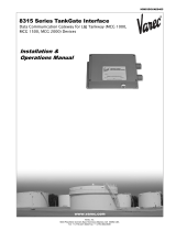
Figure 1.1 RS-232C Quick Hook-Up.
D5121M

Getting Started 1-3
Figure 1.2 RS-485 Quick Hook-Up.
be *+00025.00. The temperature reading will be in °C. Once you have a
response from the module you can turn to the Chapter 4 and get familiar with
the command set.
All modules are shipped from the factory with a setup that includes a channel
address of 1, 300 baud rate, no linefeeds, no parity, alarms off and two-
character delay. Refer to the Chapter 5 to configure the module to your
application.
RS-485 Quick Hook-up to a RS-232 port
An RS-485 module may be easily interfaced to an RS-232C terminal for
evaluation purposes. This connection is only suitable for benchtop operation
and should never be used for a permanent installation. Figure 1.3 shows the
hook-up. This connection will work provided the RS-232C transmit output is
current limited to less than 50mA and the RS-232C receive threshold is
greater than 0V. All terminals that use 1488 and 1489 style interface IC’s will
satisfy this requirement. With this connection, characters generated by the
terminal will be echoed back. To avoid double characters, the local echo on
the terminal should be turned off.
If the current limiting capability of the RS-232C output is uncertain, insert a
100Ω to 1kΩ resistor in series with the RS-232 output.
In some rare cases it may be necessary to connect the module’s DATA
pin to ground through a 100Ω to 1kΩ resistor.
D5122M

Getting Started 1-4
Figure 1.3 RS-485 Quick Hook-Up with RS-232C Port.
D5122M
Software Quick Start
The D5000M series modules are initialized at the factory to communicate
using the D5000M ASCII protocol. This allows for all setup and configura-
tions to be easily performed using the setup software. After the setup
process has been completed the D5000M can be placed in Modbus RTU
protocol mode using the “MBR” command. Disable the Modbus RTU mode
using the Modbus Disable (“MBD”) command.
Windows Quick-Start Steps:
1. Locate the Utility Software CD-ROM and place it in your computer
CD-ROM drive.
2. Using Windows 95 or higher operating systems, click on the “Start”
button in the lower left hand corner. When the menu pops up, select
“Run” and the “Browse” to the CD-ROM drive in your machine.
3. Select the “Setup.exe” file and “Run” it. This will begin installation of the
Windows Utility Software.

Getting Started 1-5
4. The installation program will run and you can select the default instal-
lation settings by pressing the “Next” button thru most of the prompt
screens.
5. Once the installation is completed, you can review the “readme.txt” file.
Or simply “Finish” the process.
6. A “Utility Software” icon will be placed on your Windows desktop. Click
on this icon to run the Utility Software.
7.All Users Manuals were installed during the Utility Software
installation process. The Users Manuals can be found on a new menu
by pressing the Windows “Start” button and selecting “Programs”. Next,
select “Data Acquisition” and then select “Manuals”. Click on the
D5000M Users Manual to open it.
8. Connect a power supply to the D5000M between the +VS terminal and
the GND terminal. The power supply voltage must be between +10 and
+30Vdc.
9. Properly connect the D5000M to a computer serial port using the “Quick
Hook-Up” diagrams in Chapter #1 of this manual using either an RS-232
or RS-485 Serial port.
10. An optional CA-3 serial cable and wiring diagram may be used to
connect an RS-232 module to a DB-9 serial port.
11. At the Utility Software main menu, select “Setup” and then select
“Modules”. A new dialog screen will open.
12. Using the drop down list box screen object, select the proper serial port
that the module is connected to.
13. Press the “Settings” button to display the serial port settings. Select the
proper COM port, set the baud rate for ‘300’. Press the “Advanced”
button and ensure that the Parity Type is set to “Mark”, Data bits is
“Seven”, Flow Control is “RTS Only” and the Stop Bits are “One”. Press
the “Open” or “Update” button.
14. Select the proper device Model Number from the drop down list box
screen object. Use only the four digits. For example, a D5121M should
be a “5121”.
15. Specify the device address. If the “Default*” terminal on the module is
connected to the “GND” terminal then any device address is acceptable.
If the “Default*” terminal is not connected to the “GND” terminal then you
must select the correct device address in the “Address” list box.

Getting Started 1-6
16. Press the “Read Setup” button at the bottom of the dialog screen. If no
errors were detected then a new dialog screen will appear with all the
current module setup values.
17. To configure the device for a Modbus system, the only values that need
to be changed are the Baud Rate, possibly the Parity type and the
Modbus Slave Address. Most Modbus systems use No Parity.
18. Set the Baud rate to the same baud rate as the Modbus master device
that this module will be connected to.
19. Select the new Modbus Slave address and check the “Enable” box.
Then press the “Apply” button to download the changes to the module.
The setup is complete.
Modbus Installation/Verification:
1. The module is now configured for the proper Baud Rate and
Modbus Slave Address. The module can now be connected directly
to the Modbus Master. Or it can be functionally checked.
2. To functionally verify the operation of the Modbus protocol make
sure that the “Default*” terminal is no longer connected to the “GND”
terminal.
3. From the Utility Software main menu select “Tools” and then select
“Evaluation Screens” and then “Modbus I/O Screen”.
4. Click on the “Settings” button and change the Baud Rate to the value
that the module is configured for.
5. Press the “Advanced” button. Select “8 Data bits”, “RTS Only”, “No
Parity” and “2 Stop Bits”. Press the “Update” or “Open” button.
6. Select the Modbus Slave Address to the same value as the module
is configured for.
7. Select Modbus function ‘04’ and register ‘000’.
8. Press the “Transmit” button.
9. Hexadecimal numbers will appear in the “Response” box. These
numbers are hexadecimal between the values of ‘0000’ and ‘ffff’.
They represent a percentage of the full scale value. If your getting
readings back that move as your input moves then the Modbus
protocol is working successfully. For more information how to
compute these values consult the Users Manual for your product.

Getting Started 1-7
DOS Quick start steps:
1. Connect a power supply to the D5000M between +Vs terminal and GND
terminal. The supply voltage must be between +10 and +30Vdc.
2. Properly connect the D5000M series to a computer using the “quick
hook-up” diagrams in chapter #1 of this manual using either an RS-232
or RS-485 serial port.
3. Locate the S1000 Utility software diskette and copy files from the S1000
sub-directory on the computer hard drive and run the 1000.bat file.
4. Configure the main menu “Host” RS-232 Port settings and correct
COMx: port baud rate. Note: If the “Default*” pin on D1000M is
connected to GND then select 300 baud as host computer baud rate and
select no parity.
5. Select main menu “Setup” and enter the D5000M device address and
four digit model number. For example, enter 5112 for a D5112M analog
input module.
6. At the next configuration screen make alterations to Baud Rate, Parity
type and any other required parameters. Press the <F10> function key
to transmit the new setup values. Once the values have been transmit-
ted press the <ESC> key back to the program main menu.
7. Select “Misc” followed by “Enable Modbus Mode” to specify the Modbus
Slave address. Using the <+><-> keys, or left mouse button, increment
the screen address value to desired Modbus Slave address and press
<F10> to transmit the value.
8. Remove the connection between “Default*” and GND, which performs
internal reset, to enable Modbus RTU mode. If there was no connection
between “Default*” and GND then cycle the power on device to force a
reset and enable Modbus Mode.
The device is now configured for Modbus RTU mode and can be connected
to a RS-485 based Modbus master system.

Getting Started 1-8
Modbus Installation/Verification:
1. The D5000M module is now configured for the proper Baud Rate and
Modbus Slave Address. The module can now be connected directly to
the Modbus Master. Or it can be functionally checked.
2. To functionally verify the operation of the Modbus protocol make sure
that the “Default*” terminal is no longer connected to the “GND” terminal.
3. From the Utility Software main menu select “Tools” and then select
“Evaluation Screens” and then “Modbus I/O Screen”.
4. Click on the “Settings” button and change the Baud Rate to the value
that the module is configured for.
5. Press the “Advanced” button. Select “8 Data bits”, “RTS Only”, “No
Parity” and “2 Stop Bits”. Press the “Update” or “Open” button.
6. Select the Modbus Slave Address to the same value as the module is
configured for.
7. Select Modbus function ‘04’ and register ‘000’.
8. Press the “Transmit” button.
9. Hexadecimal numbers will appear in the “Response” box. These
numbers are hexadecimal between the values of ‘0000’ and ‘ffff’. They
represent a percentage of the full scale value. If your getting readings
back that move as your input moves then the Modbus protocol is
working successfully. For more information on how to compute these
values consult the Users Manual for your product. For more information
D5000M Modbus portocol and scaling of data see Chapter 4 and
Appendix C respectively.

A functional diagram of a typical module is shown in Figure 2.1. It is a useful
reference that shows the data path in the module and to explain the function
of many of the module’s commands.
The first step is to acquire the sensor signal and convert it to digital data. In
Figure 2.1, all the signal conditioning circuitry has been lumped into one
block, the analog/digital converter (A/D). Autozero and autocalibration is
performed internally and is transparent to the user.
The full-scale output of each channel may be trimmed using the Trim Span
(TS) command. The TS command adjusts the calibration values for each
channel that stored in the internal EEPROM. The TS command should only
be used to trim the accuracy of the unit with a laboratory standard reference
applied to the sensor input.
The trimmed data flows into either of two digital filters. The filter selection is
performed automatically by the microprocessor after every A/D conversion.
The filter selection depends on the difference of the current A/D output data
and the previous data stored in the output data register. If the least significant
decimal digit from the A/D differs from the old output data by more than 10
counts, the large signal filter is selected. If the change is less than 10 counts,
the small signal filter is used.
The two-filter system allows for different degrees of filtering depending on
the rate of the input change. For steady-state signals, the small-signal filter
averages out noise and small input changes to give a stable steady-state
output. The large-signal filter is activated by step changes or very noisy input
signals. The time constants for the two filters can be specified independently
with the SetUp (SU) command. The filter values are stored in nonvolatile
memory. Typically, the small-signal filter is set to a larger time constant than
the large-signal filter. This gives very good noise rejection along with fast
response to step inputs.
The scaled data is summed with data stored in the Output Offset Register
to obtain the final output value. The output offset is controlled by the user and
has many purposes. The data in the Output Offset Register may be used to
trim any offsets caused by the input sensor. It may be used to null out
undesired signal such as a tare weight. The Trim Zero (TZ) command is used
to adjust the output to any desired value by loading the appropriate value in
the offset register. The offset register data is nonvolatile.
The output data may be read with the Read Data (RD) command.
Chapter 2
Functional Description

Functional Description 2-2

Introduction
The D5000M modules has been carefully designed to be easy to interface
to all popular computers and terminals. All communications to and from the
modules are performed with printable ASCII characters. This allows the
information to be processed with string functions common to most high-level
languages such as BASIC. For computers that support RS-232C, no special
machine language software drivers are necessary for operation. The
modules can be connected to auto-answer modems for long-distance
operation without the need for a supervisory computer. The ASCII format
makes system debugging easy with a dumb terminal.
This system allows multiple modules to be connected to a communications
port with a single 4-wire cable. Up to 30 RS-485 modules may be strung
together on one cable.
The modules communicate with the host on a polling system; that is, each
module responds to its own unique address and must be interrogated by the
host. A module can never initiate a communications sequence. A simple
command/response protocol must be strictly observed to avoid communi-
cations collisions and data errors.
Communications to the D5000M modules is performed with two-character
ASCII command codes such as RD to Read Data from the analog input. A
complete description of all commands is given in the Chapter 4. A typical
command/response sequence would look like this:
Command: $1RD
Response: *+00123.00
A command/response sequence is not complete until a valid response is
received. The host may not initiate a new command until the response from
a previous command is complete. Failure to observe this rule will result in
communications collisions. A valid response can be in one of three forms:
1) a normal response indicated by a ‘ * ‘ prompt
2) an error message indicated by a ‘ ? ‘ prompt
3) a communications time-out error
When a module receives a valid command, it must interpret the command,
perform the desired function, and then communicate the response back to
the host. Each command has an associated delay time in which the module
is busy calculating the response. If the host does not receive a response in
an appropriate amount of time specified in Table 3.1, a communications
time-out error has occurred. After the communications time-out it is as-
sumed that no response data is forthcoming. This error usually results when
Chapter 3
Communications

Communications 3-2
an improper command prompt or address is transmitted. The table below
lists the timeout specification for each command:
Mnemonic Timeout
RD 10 mS
All other commands 100 mS
Table 3.1 Response Timeout Specifications.
The timeout specification is the turn-around time from the receipt of a
command to when the module starts to transmit a response.
Data Format
All modules communicate in standard NRZ asynchronous data for-
mat. This format provides one start bit, seven data bits, one parity bit
and one stop bit for each character.
RS-232C
RS-232C is the most widely used communications standard for information
transfer between computing equipment. RS-232C versions of the D5000 will
interface to virtually all popular computers without any additional hardware.
The advantages offered by the RS-232C standard are:
1) widely used by all computing equipment
2) no additional interface hardware in most cases
3) separate transmit and receive lines ease debugging
4) compatible with dumb terminals
However, RS-232C suffers from several disadvantages:
1) low noise immunity
2) short usable distance
3) greater communications delay in multiple-module systems
4) less reliable–loss of one module; communications are lost
5) wiring is slightly more complex than RS-485
6) host software must handle echo characters
RS-232 Module Connection
Figure 1.1 shows the connections necessary to attach one module to a host.
Use the Default Mode to enter the desired address, baud rate, and other
setups (see Setups).

Communications 3-3
Software Considerations
If the host device is a computer, it must be able to handle the echoed
command messages on its Receive input along with the responses from the
module. This can be handled by software string functions by observing that
a module response always begins with a ‘ * ‘ or ‘ ? ‘ character and ends with
a carriage return.
RS-485
RS-485 is a communications standard to satisfy the need for multidropped
systems that can communicate at high data rates over long distances. RS-
485 is similar to RS-422 in that it uses a balanced differential pair of wires
switching from 0 to 5V to communicate data. RS-485 receivers can handle
common mode voltages from -7V to +12V without loss of data, making them
ideal for transmission over great distances. RS-485 differs from RS-422 by
using one balanced pair of wires for both transmitting and receiving. Since
an RS-485 system cannot transmit and receive at the same time it is
inherently a half-duplex system. RS-485 offers many advantages over RS-
232C:
1) balanced line gives excellent noise immunity
2) can communicate with D5000M modules at 115200 baud
3) communications distances up to 4,000 feet.
4) true multidrop; modules are connected in parallel
5) can disconnect modules without losing communications
6) up to 247 modules on one line using RS-485 repeaters
7) no communications delay due to multiple modules
8) simplified wiring using standard telephone cable
RS-485 does have disadvantages. Very few computers or terminals have
built-in support for this new standard. Interface boards are available for the
IBM PC and compatibles and other RS-485 equipment will become avail-
able as the standard gains popularity. An RS-485 system usually requires
an interface.
We offer the A1000 and A2000 interface converters that will convert RS-232
signals to RS-485 or repeat RS-485 signals. The A1000 converters also
include a +24Vdc, one amp power supply for powering D5000M series
modules. The A1000 or A2000 connected as an RS-485 repeater can be
used to extend an existing RS-485 network on one serial port.
RS-485 Multidrop System
Figure 3.1 illustrates the wiring required for multiple-module RS-485 sys-
tem. Notice that every module has a direct connection to the host system.
Any number of modules may be unplugged without affecting the remaining
modules. Each module must be setup with a unique address and the

Communications 3-4
addresses can be in any order. All RS-485 modules must be setup for no
echo to avoid bus conflicts (see Setup). Also note that the connector pins on
each module are labelled with notations (B), (R), (G), and (Y). This
designates the colors used on standard 4-wire telephone cable:
Label Color
(B) GND Black
(R) V+ Red
(G) DATA* (-) Green
(Y) DATA (+) Yellow
This color convention is used to simplify installation. If standard 4-wire
telephone cable is used, it is only necessary to match the labeled pins with
the wire color to guarantee correct installation.
DATA* on the label is the complement of DATA (negative true).
To minimize unwanted reflections on the transmission line, the bus should
be arranged as a line going from one module to the next. ‘Tree’ or random
structures of the transmission line should be avoided. When using long
transmission lines and/or high baud rates, the data lines should be termi-
nated at each end with 200 ohm resistors. Standard values of 180 ohms or
220 ohms are acceptable.
During normal operation, there are periods of time where all RS-485 drivers
are off and the communications lines are in an 'idle' high impedance
condition. During this condition, the lines are susceptible to noise pickup
which may be interpreted as random characters on the communications
line. To prevent noise pickup, all RS-485 systems should incorporate 1K
ohm bias resistors as shown in Figure 3.1. The resistors will maintain the
data lines in a 'mark' condition when all drivers are off.
A1000 series converter boxes have the 1KΩ resistors built-in. The resistors
are user-selectable via dip switch located on the rear panel of the A1000.
Special care must be taken with very long busses (greater than 1000 feet)
to ensure error-free operation. Long busses must be terminated as de-
scribed above. The use of twisted cable for the DATA and DATA* lines will
greatly enhance signal fidelity. Use parity and checksums along with the ‘#’
form of all commands to detect transmission errors. In situations where
many modules are used on a long line, voltage drops in the power leads
becomes an important consideration. The GND wire is used both as a power

Communications 3-5
connection and the common reference for the transmission line receivers in
the modules. Voltage drops in the GND leads appear as a common-mode
voltage to the receivers. The receivers are rated for a maximum of -7V. of
common-mode voltage. For reliable operation, the common mode voltage
should be kept below -5V.
To avoid problems with voltage drops, modules may be powered locally
rather than transmitting the power from the host. Inexpensive 'calculator'
type power supplies are useful in remote locations. When local supplies are
used, be sure to provide a ground reference with a third wire to the host or
through a good earth ground. With local supplies and an earth ground, only
two wires for the data connections are necessary.
Communications Delay
All D5000M modules with RS-485 outputs are setup at the factory to provide
two units of communications delay after a command has been received (see
Chapter 5). This delay is necessary when using host computers that transmit
a carriage return as a carriage return-linefeed string. Without the delay, the
linefeed character may collide with the first transmitted character from the
module, resulting in garbled data. If the host computer transmits a carriage
return as a single character, the delay may be set to zero to improve
communications response time.

Communications 3-6
/