Page is loading ...

1
MODEL TA-4/170-H
DC
Welding Generator
INSTRUCTION MANUAL
• STICK
• TIG-Scratch Start
• Auxiliary Power
August 2,2002
Manual No. 0-2625/CSA
MI118-06-01-06

2
ref. TAF4170.TIF
TA-4/170-H
DC
Welding generator

3
Proposition 65
WARNING: This product, when used for welding or cutting,
produces fumes or gases which contain chemicals known to the
State of California to cause birth defects and, in some cases,
cancer. (California Health & Safety Code Sec.25249.5 et seq.)

4
WARNING
Read and understand this entire Instruction Manual and your employer’s safety practices before
installing, operating, or servicing the equipment.
WARNING
While the information contained in this Instruction Manual represent our best judgement, Thermal
Arc assumes no liability for its use.
Thermal Arc DC Welding Generator Model TA-4/170-H
Instruction Manual Number 0-2625/CSA
Published by:
Thermal Arc
2200 Corporate Drive
Troy OH
USA 45373
Ph: (1) 937 440 0100
Copyright 1997 by
Thermal Arc
All right reserved.
Reproduction of this work, in whole or in part, without written permission of the publisher is
prohibited.
The publisher does not assume and hereby disclaims any liability to any part for any loss or damage
caused by any error or omission in the Thermal Arc DC Welding Generator Model TA-4/170-H
Instruction Manual, whether such error results from negligence, accidental, or any other cause.
August 1, 1997

5
TABLE OF CONTENTS
1. GENERAL INFORMATION.....................................................................................................6
1.01 Notes, Cautions and Warnings.........................................................................................................................6
1.02 Important Safety Precautions ...........................................................................................................................6
1.03 Publications......................................................................................................................................................8
1.04 Note, Attentions et Avertissement....................................................................................................................9
1.05 Precations De Securite Importantes .................................................................................................................9
1.06 Publications....................................................................................................................................................11
2. STATEMENT OF WARRANTY.............................................................................................13
3. TECHINICAL SPECIFICATIONS.........................................................................................15
4. FRONT PANEL DESCRIPTION............................................................................................16
5. OVERAL DIMENSIONS WEIGHT BASE MOUNTING....................................................18
6. SPECIFICATIONS ...................................................................................................................19
7. INSTALLING WELDING GENERATOR.............................................................................20
8. WARNING .................................................................................................................................21
9. GENERATOR AUXILIARY POWER SYSTEM..................................................................22
9.01 SELECTING EQUIPMENT..........................................................................................................................22
10. WIRING OPTIONAL 230 VOLT PLUG................................................................................23
11. GROUNDING THE GENERATOR TO A TRUCK OR A TRAILER FRAME................24
12. GROUNDING THE GENERATOR WHEN CONNECTING TO HOME, SHOP, OR
FARM WIRING ........................................................................................................................24
13. SELECTING AND PREPARING WELD OUTPUT CABLES............................................25
14. TYPICAL PROCESS CONNECTIONS .................................................................................26
15. POWER REQUIRED TO START MOTOR..........................................................................26
16. SELECTING WELD CABLES SIZES ...................................................................................27
17. WELD OUTPUT CONNECTION...........................................................................................28
18. SEQUENCE OF OPERATION................................................................................................29
18.01 STARTING....................................................................................................................................................29
18.02 SHELDED METAL ARC WELDING (SMAW) ..........................................................................................30
18.03 STOPPING THE ENGINE............................................................................................................................31
19. ROUTINE MAINTENANCE...................................................................................................32
20. PARTS LIST..............................................................................................................................35
20.01 TROLLEY 4 : TWO WHEELS TROLLEY WITH HANDLES (Optional accessory) .................................38
21. WIRING DIAGRAM ................................................................................................................40

6
1. GENERAL INFORMATION
GASES AND FUMES
1.01 Notes, Cautions and Warnings
Gases and fumes produced during the Arc
welding/cutting process can be dangerous and
hazardous to your healt.
Throughout this manual,notes,cautions,and
warnings are used to highlight important
information. These highlights are categorized as
follows:
• Keep all fumes and gases from the breathing
area. Keep your head out of the welding fume
plume.
NOTE
• Use an air-supplied respirator if ventilation is
not adeguate to remove all fumes and gases.
An operation, procedure, or background
information wich requires additional emphasis or
is helpful in efficent operation of the system
.
• The kinds of fumes and gases from the arc
welding/cutting depend on the kind of metal
being used coatings on the metal, and the
different process. You must be very careful
when cutting or welding any metals which may
contain one or more of the following:
CAUTION
A procedure which, if not properly followed, may
cause damage to the equipment.
Antimony Chromium Mercury
Arsenic Cobalt Nickel
Barium Copper Selenium
Beryllium Lead Silver
Cadmium Manganese
WARNING
A procedure which, if not properly followed, may
cause injury to the operator or others in the
operating area.
• Always read the Material Safety data Sheets
(MSDS) that should be supplied with the
material you are using. These MSDS will give
you the information regarding the kind and
amount of fumes and gases that may dangerous
to your healt.
1.02 Important Safety Precautions
• For information on how to test for fumes and
gases in your workplace, refer to item 1 in
Subsection 1.03, Publication in this manual.
WARNING
• Use special equipment, such as water or down
draft welding/cutting tables, to capture fumes
and gases.
OPERATION AND MAINTENANCE OF
WELDING EQUIPMENT CAN BE DANGEROUS
AND HAZARDOUS TO YOUR HEALT.
• Do not use the welding torch in an area where
combustible or explosive gases or materials
are located.
To prevent possible injury, read, understand, and
follow all warnings, safety precautions and
instructions bedore using the equipment. Call 1-
603-298-5711 or your local distributor if you have
any questions.
• Phosgene, a toxic gas, is generated from the
vapors of chlorinated solvents and cleansers.
Remove all sources of these vapors.
GENERAL INFORMATION

7
ELECTRIC SHOCK
Electric Shock can injure or kill. The arc welding
process uses and produces high voltage electrical
energy. This electric energy can cause severe or
fatal shock to the operator or others in the
workplace
• Never touch any parts that are electrically
“live” or “hot”.
• Wear dry gloves and clothing. Insulate
yourself from the work piece or other parts of
the welding circuit.
• Repair or replace all worn ar damage parts.
• Extra care must be taken when the workplace
is moist or damp.
• Install and mantain equipment according to
NEC code, refer to item 4 in Subsection 1.03,
Publications.
• Disconnect power source before performing
any service or repairs.
• Read and follow all the instruction in the
Operating Manual.
FIRE AND EXPLOSION
Fire and explosion can be caused by hot slag,
sparks or the arc weld.
• Be sure there is no combustible or flammable
material in the workplace. Any material that
cannot be removed must be protected.
• Ventilate all flammable or explosive vapors
from the workplace.
• Do not cut or weld on containers that may
have held combustibles.
• Provide a fire watch when working in an area
where fire hazards may exist.
• Hydrogen gas may be formed and trapped
under aluminium workpieces when they
are cut underwater or while using a water
table. DO NOT cut aluminium alloys
underwater or on a water table unless the
hydrogen gas can be eliminated or
dissipated. Trapped hydrogen gas that is
ignited will cause an explosion.
NOISE
Noise can cause permanent hearing loss. Arc
welding/cutting processes can cause noise levels
to exceed safe limits. You must protect your ears
from loud noise to prevent permanent loss of
hering.
• To protect your hearing from loud noise wear
protective ear plugs and/or ear muffs. Protect
others in the workplace.
• Noise levels should be measured to be sure the
decibels (sound) do not exceed safe levels.
•
For information on how to test for noise,
see item 1 in Subsection 1.03, Publications,
in this manual.
ARC WELDING RAYS
Arc Welding/Cutting Rays can injure your
eyes and burn your skin. The arc welding
cutting process produces very bright ultra
violet and infra red light. These arc rays will
damage your eyes and burn your skin if you
are not properly protected.
• To protect your eyes, always wear a welding
helmet or shield. Also always wear safety
glasses with side shields goggles or other
protective eye wear.
• Wear welding gloves and suitable clothing to
protect your skin from the arc rays and sparks
GENERAL INFORMATION

8
Keep helmet and safety glasses in good condition.
replace lenses when cracked, chipped or dirty.
• Protect others in the work area from the arc
rays. Use protective booths, screens or shields.
• Use the shade of lens as raccomanded in
Subsection 1.03, item 4.
1.03 Publications
Refer to the following standards or their latest
revisions for more information:
1. OSHA, SAFETY AND HEALTH
STANDARDS, 29CFR 1910, obtainable from
the Superintendent of Documents, U.S.
Government Printing Office, Washington,
D.C. 20402.
2. ANSI Standard Z49.1, SAFETY IN
WELDING AND CUTTING, obtainable from
the American Welding Society, 550 N.W.
LeJeune Rd, Miami, FL 33126.
3. NIOSH, SAFETY AND HEALTH IN ARC
WELDING AND GAS WELDING AND
CUTTING, Obtainable from the
Superintendent of Documents, U.S.
Government Printing Office, Washington,
D.C. 20402.
4. ANSI Standard Z87.1, SAFE PRACTICES
FOR OCCUPATION AND EDUCATIONAL
EYE AND FACE PROTECTION, Obtainable
from American National Standard Institute,
1430 Broadway, New York, NY 10018.
5. ANSI Standard Z41.1, STANDARD FOR
MEN’S SAFETY-TOE FOOTWEAR,
obtainable from the American National
Standards Institute, 1430 Broadway, New
York, NY 1018.
6. ANSI Standard Z49.2, FIRE PREVENTION
IN THE USE OF CUTTING AND WELDING
PROCESSES, Obtainable from American
National Standard Institute, 1430 Broadway,
New York, NY 10018.
7. AWS Standard A6.0, WELDING AND
CUTTING CONTAINERS WICH HAVE
HELD COMBUSTIBLES, obtainable from
American Welding Society, 550 N.W. Lejeune
Rd, Miami, FL33126.
8. NFPA Standard 51, OXYGEN-FUEL GAS
SYSTEMS FOR WELDING, CUTTING AND
ALLIED PROCESSES, obtainable from the
National Fire Protection Association,
Batterymarch Park, Quincy, MA 02269.
9. NFPA Standard 70, NATIONAL
ELECTRICAL CODE; obtainable from the
National Fire Protection Association,
Batterymarch Park, Quincy, MA 02269
10. NFPA Standard 51B, CUTTING AND
WELDING PROCESSES, obtainable from the
National Fire Protection Association,
Batterymarch Park, Quincy, MA 02269.
11. CGA Pamphlet P-1, SAFE HANDLING OF
COMPRESSED GASES IN CYLINDERS,
obtainable from the Compressed Gas
Association, 1235 Jefferson Davis Highway,
Suite 501 Arlington, VA 22202.
12. CSA Standard W117.2, CODE FOR SAFETY
IN WELDING AND CUTTING, obtainable
from the Canadian Standards Association,
Standards Sales, 178 Rexdale Boulevard,
Rexdale, Ontario, Canada M9W 1R3.
13. NWSA booklet, WELDING SAFETY
BIBLIOGRAPHY obtainable from the
National Welding Supply Association, 1900
Arch Street, Philadelphia PA 19103.
14. American Welding Society Standard
AWSF4.1, RECOMMENDED SAFE
PRACTICES FOR THE PREPARATION
FOR WELDING AND CUTING OF
CONTAINERS AND PIPING THAT HAVE
HELD HAZARDOUS SUBSTANCES
obtainable from the American Welding
Society, 550 N.W. LeJeune Rd, Miami, FL
33126.
GENERAL INFORMATION

11
BRUIT
Le bruit peut provoquer une perte permanente de
l’ouie. Les procédés de soudage à l’arc de plasma
peuvent provoquer des niveaux sonores
supérieures aux limites normalement acceptables.
Vous dùvez vous protéger les oreilles contre les
bruits forts afin d’éviter une perte permanente de
l’ouïe.
• Pour protéger votre ouïe contre les bruits forts,
portez des taòpons protecteurs st/ou des
protections auriculaires. Protégez également
les autres personnes se trouvant sur le lieu de
travail.
• Il faut measurer les niveaux sonores afin
d’assurer que les décibels (le bruit) ne
dépassent pas les niveaux sûrs.
• Pour des renseignements sur la manière de
tester le bruit, consultez l’article 1, page 5.
1.06 Publications
Consultez les normes suivents ou les révisions les
plus récentes ayant été faites à celles-ci pour de
plus amples renseignements:
1. OSHA, NORMES DE SÉCURITÉ DU
TRAVAIL ET DE LA PROTECTION DE LA
SANTÉ, 29CFR 1910, disponible auprès du
Superintenent of documents, U.S. Government
Printing Office, Washington, D.C. 20402.
2. Norme ANSI Z49.1, LA SÉCURITÉ DES
OPÉRATIONS DE COUPE ET DE
SOUDAGE, disponible auprésde la Société
Americaine de Soudage (American Welding
Society, 550 N.W. LeJeune Rd, Miami, FL
33126.
3. NIOSH LA SÉCURITÉ ET LA SANTÉ LORS
DES OPÉRATIONS DE COUPE ET DE
SOUDAGE A L’ARC ET AU GAZ,
disponible auprès du Superintendent of
Documents, U.S. Government Printing Office,
Washington, D.C. 20402.
4. Norme ANSI Z87.1, PARTIQUES SURES
POUR LA PROTECTION DES YEUX ET
DU VISAGE AU TRAVAIL ET DANS LES
ECOLES, disponible de l’ Institute Américain,
des Normes Nationales (American National
Standard Institute), 1430 Broadway, New
York, NY 10018.
5. Norme ANSI Z41.1, NORMES POUR LES
CHAUSSURES PROTECTRICES, disponible
auprès de l’American National Standards
Institute, 1430 Broadway, New York, NY
1018.
6. Norme ANSI Z49.2, PRÉVENTION DES
INCENDIES LORS DE L’EMPLOI DE
PROCÉDÉS DE COUPE ET DE SOUDAGE,
disponible aupres de l’American National
Standard Institute, 1430 Broadway, New York,
NY 10018.
7. Norme A6.0 de l’Association Américaine du
Soudage (AWS), LE SOUDAGE ET LA
COUPE DE CONTENEURS AYANT
RENFERMÉ DES PORDUITS
COMBUSTIBLES disponible auprès de la
American Welding Society, 550 N.W. Lejeune
Rd, Miami, FL33126.
8. Norme 51 de l’Association Américaine pour la
Protection contre les Incendies (NFPA), LES
SYSTEMS A GAZ AVEC ALIMENTATION
EN COUPE ET LES PROCÉDÉS ASSOCIÉS,
disponible auprès de la National Fire
Protection Association, Batterymarch Park,
Quincy, MA 02269.
9. Norme 70 de la NFPA,CODE ELECTRIQUE
NATIONAL, disponible aupres de la National
Fire Protection Association, Batterymarch
Park, Quincy, MA 02269
10. Norme 51B de la NFPA, LES PROCÉDÉS DE
COUPE ET DE SOUDAGE, disponible aupres
de la National Fire Protection Association,
Batterymarch Park, Quincy, MA 02269.
11. Brochure CGA P-1, LA MANIPULATION
SANS RISQUE DES GAZ COMPRIMÉS EN
CYLINDRES, disponible aupres de
l’Association des Gaz Comprimes
(Compressed Gas Association), 1235 Jefferson
Davis Highway, Suite 501 Arlington, VA
22202.
GENERAL INFORMATION

12
12. Norme CSA W117.2, CODE DE SÉCURITÉ
POUR LE SOUDAGE ET LA COUPE,
disponible aupres de l’Association des Normes
Canadiennes, Standards Sales, 178 Rexdale
Boulevard, Rexdale, Ontario, Canada M9W
1R3.
13. Invret NWSA, BIBLIOGRAPHIE SUR LA
SÉCURITÉ DU SOUDAGE, disponible
auprès de l’Association Nationale de
Fournitures de Soudage (National Welding
Supply Association), 1900 Arch Street,
Philadelphia PA 19103.
14. Norme AWSF4.1 de l’Association Américaine
de soudage , RECOMMANDATIONS DE
PRATIQUES SURES POUR LA
PRÉPARATION A LA COUPE ET AU
SOUDAGE DE CONTENEURS ET
TUYAUX AYANT RENFERMÉ DES
PRODUITS DANGEREUX, disponible auprès
de l’American Welding Society, 550 N.W.
LeJeune Rd, Miami, FL 33126.
15. Norme ANSI Z88.2, PRATIQUES DE
PROTECTION RESPIRATOIRE, disponible
auprès de l’American National Standards
Instiute, 1430 Broadway, New York, NY
10018.
GENERAL INFORMATION

13
2. STATEMENT OF WARRANTY
LIMITED WARRANTY: Thermal Arcâ, Inc. A Thermadine Company, warrants that its products will be free of
defects in workmanship or material. Should any failure to conform to this warranty appear within the time period
applicable to the Thermal Arc products as stated below, Thernal Arc shall, upon notification thereof and substantiation
that the product has been stored, installed, operated, and manteined in accordance with Thermal Arc’s specifications,
instructions, recomandations and recognized standard industry practice, and not subjet to misuse, repair, neglet,
alteration, or accident, correct such defects by suitable repair or replacement, at Thermal Arc’s sole option, of any
components or parts of the product determinated by Thermal Arc to be defective.
THERMAL ARC MAKES NO OTHER WARRANTY, EXPRESS OR IMPLIED. THIS WARRANTY IS
EXCLUSIVE AND IN LIEU OF ALL OTHERS, INCLUDING, BUT NOT LIMITED TO ANY WARRANTY
OF MERCHANTABILITY OR FITNESS FOR ANY PARTICULAR PURPOSE.
LIMITATION OF LIABILITY: Thermal Arc shall not under any circumstances be liable for special or consequential
damages, such us, but not limited to, damage or loss of purchased or replacement goods, or claims of customers of
distributor (hereinafter “Purchaser”) for service interruption. The remedies of the Purchaser set forth herein are
exclusive and the liability of Thermal Arc with respect to any contract, or anything done in connection therewith such as
the performance or breach thereof, or from the manufacture, sale, delivery, resale, or use of any goods covered by or
furnished by Thermal Arc whether arising out of contract, negligence, strict tort, or under any warranty, or otherwise,
shall not, except as expressly provided herein, exceed the price of the goods upon which such liability is based. No
employee, agent, or rapresentative of Thermal Arc is authorized to change this warranty in any way or grant any other
warranty.
PURCHASER’S RIGHTS UNDER THIS WARRANTY ARE VOID IF REPLACEMENT PARTS OR
ACCESSORIES ARE USED WHICH IN THERMAL ARC’S SOLE JUDGEMENT MAY IMPAIR THE
SAFETY OR PERFORMANCE OF ANY THERMAL ARC PRODUCT.
PURCHASER’S RIGHTS UNDER THIS WARRANTY ARE VOID IF THE PRODUCT IS SOLD TO
PURCHASER CY NONAUTHORIZED PERSONS.
Except with regards to the products listed below, this warranty shall remain effective there (3) years from from the date
Thermal Arc’s authorized distributor delivers the product to Purchaser, but in no event more than (4) years from the date
Thermal Arc delivers the product to the authorized distributor.
Shorter warranty periods apply to the products listed below. On these products, the warranty is effective for the time
stated below beginning on the date that the authorized distributor delivers the products to the Purchaser.
Notwithstanding the foregoing, in no event shall the warranty period extend more that the time stated plus one year from
the date Thermal Arc delivered the product to the authorized distributor.
ALL OTHER
P-WEE, PRO-LITE
POWER SUPPLIES POWER SUPPLIES INVERTERS LABOR
MAIN POWER MAGNETICS (STATIC & ROTATING) 3 YEARS 2 YEARS 1 YEAR
ORIGINAL MAIN POWER RECTIFIER 3 YEARS 2 YEARS 1 YEAR
CONTROL PC BOARD 3 YEARS 2 YEARS 1 YEAR
ALL OTHER CIRCUITS AND COMPONENTS INCLUDING
BUT NOT LIMITED TO, CONTACTORS, RELAYS,
SOLENOIDS, PUMPS, POWER SWITCHING SEMI-
CONDUCTORS.
1 YEAR 1 YEAR 1 YEAR
ENGINES: ENGINES ARE NOT WARRANTED BY THERMAL ARC, ALTHOUGH MOST ARE
WARRANTED BY THE ENGINE MANUFACTURER. SEE THE ENGINE MANUFACTURES WARRANTY
FOR THE DETAILS.
CONSOLES, CONTROL EQUIPMENT, HEAT
1 YEAR 1 YEAR 1 YEAR
EXCANGES, AND ACCESSORY EQUIPMENT
TORCH AND LEADS
180 DAYS 180 DAYS
180 DAYS
REPAIR/ REPLACEMENT PARTS
90 DAYS 90 DAYS
90 DAYS
GENERAL INFORMATION

14
Warranty repairs or replacement claims under this limited warranty must be submitted to Thermal Arc by an authorized
Thermal Arcâ repair facility within thirty (30) days of the repair. No transportation costs of any kind will be paid under
this warranty. Transportation charges to send products to an authorized warranty repair facility shall be the
responsability of the customer. All returned goods shall be at the customer’s risk and expense. This warranty supersedes
all previous Thermal Arc warranties.
Thermal Arcâ is a Registred trademark of Thermadyne Industries Inc.
Effective January 1,1998
GENERAL INFORMATION

15
3. TECHINICAL SPECIFICATIONS
WELDING GENERATOR DC
DC amperage range 40÷170 of continuous control stepless
DC welding current 170A 60% duty cycle
DC welding current 140A 100% duty cycle
VOLTAGE
CC 90V OCV
AUXILIARY POWER
60Hz Single phase 115V 2kVA - 230 4kVA
ENGINE
Make/Type HONDA
Model series GX 270
Number of cylinders 1
Displacement 270 cc.
Power 9 HP
Engine speed 3600 r.p.m.
Cooling system Air
Starting system Manual recoil
Oil capacity 1,1 l. - 0,3 gl.
Fuel capacity 6 l. - 1,6 gl.
Fuel consumption 2,9 l/h - 0,76 gl./h

16
4. FRONT PANEL DESCRIPTION
1 GFCI 115V Duplex Receptacle - Ground fault interrupt protection receptacles for 115V 60Hz
power source
2 115V 20A Circuit Breakers - Push to reset. Controls 115V power source for the 115V duplex
GFCI receptacle.
3 230V 15A Circuit Breakers - Push to reset. Controls 230V power source for the 230V
receptacle.
4 230V/115V Single Phase Receptacle - Supplies 60Hz single-phase power at weld/power
speed
5 Hourmeter
ref. TA1170C1.DWG

17
FRONT PANEL DESCRIPTION
1 Earth Ground connection
2 Welding socket : Work - Negative connection 120/170A
3 Welding socket : Work - Negative connection 80/130A
4 Fine adjustment - controls throttle for fine welding control of current CC. Rotating this
control in a clockwise direction increases the amperage or voltage output. The scale
surrounding the control represents approximate actual amperage.
5 Welding socket : Work - Negative connection 40/90A
6 Welding socket : Electrode - Positive connection
7 Serial number
ref. TA41702C.DWG

18
5. OVERAL DIMENSIONS WEIGHT BASE
MOUNTING
OVERALL DIMENSION
MAXIMUM WELDING GENERATOR OPERATING ANGLES
Do not exceed operating amgles while running or engine damage will occur.
Dimensions
Height 510 mm 20.07 in
Width 490 mm 19.29 in
Lenght 730 mm 28.74 in
Weight 93 Kg 205 lb
ref. T41701.TIF
ref. TA41702.TIF

19
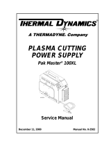
6. SPECIFICATIONS
DESCRIPTION
The Thermal Arc TA-4/170 H is a gasoline
engine driven DC welding generator. This
unit is designed for use with Shielded Metal
Arc Welding (SMAW) processes.
NOTE
Volt-ampere curves show the voltage and
amperage output capabilities of the welding
power source. Curves of other settings will
fall between the curves shown.
DUTY CYCLE
The duty cycle of a welding generator is the
percentage of a ten minute period that welding
generator can be operated at a given output
without causing overheating and damaging of
the unit. This unit is rated at 60 percent duty
cycle when operated at 170 amperes. The unit
can be operated at 170 amperes for six
consecutives minutes, but it must operate at
no load for the remaining four minutes to
allow proper cooling. If the welding amperes
decrease, the duty cycle increases. If the
welding amperes are increased beyond rated
output, the duty cycle will decrease.
CAUTION
EXCEEDING DUTY CYCLE RATINGS
will cause the thermal overload protection
circuit to become energized and shut down
output until the cools to normal operating
temperature.
CAUTION
CONTINUAL EXCEEDING OF DUTY
CYCLE RATINGS can cause damage to the
welding power source.
• Do not exceed indicated duty cycles.
NOTE: Full output may not be
achived before Engine break-in time.
Engine break-in time is Approx. 80
hours.
Ref. TA4170.TIF
Volt-Ampere Curves

20
7. INSTALLING WELDING GENERATOR
1. Lifting forks.
2. Trailer
Install unit on trailer according to trailer manufacturing.
Movement
Do not lift unit from
1
OR
Location
Airflow Clearance
ref.TA41703.TIF
OR
2
Ref. TA41705.TIF
Ref. TA41704.TIF
500mm 19.7 in
500mm 19.7 in
500mm 19.7 in
500mm 19.7 in

21
8. WARNING
ENGINE FUEL CAN CAUSE FIRE OR EXPLOSION.
- Stop engine before fueling.
- Do not fuel while smoking or near sparks or flames.
- Do not overfill tank-clean up any spilled fuel.
REMOVE FUEL CAP SLOWLY-FUEL SPRAY MAY CAUSE INJURY.
FUEL MAY BE UNDER PRESSURE.
Rotate fuel cap slowly and wait until hissing stops before removing cap.
Check all fluids daily. Engine must be cold and on a level surface.
Add fresh fuel starting engine the first time.
Wipe dipstick clean and check oil : if oil is not up to full mark, add oil.
ref. TA500D8.TIF
Full
Full
Ref. TA41706.TIF
Gasoline onl
y

22
9. GENERATOR AUXILIARY POWER SYSTEM
9.01 SELECTING EQUIPMENT
WARNING
1. Auxiliary power receptacles.
- Neutral bonded to frame.
2. 3-Prong plug from case.
Grounded equipment.
3. 2-Prong plug from double insulated equipment.
Simultaneous welding and auxiliary power
(Fine Current Control set at Maximum)
Weld current DC Auxiliary power single phase 115/230V
170 A / 26.8 V 0.5 kVA
120 A / 24.8 V 2 kVA
70 A / 22.8 V 3.5 kVA
0 A / 0 V 4 KVA
Be sure equipment
has this symbol
and/or wordin
g
.
Double
insulation
Proper equipment to use
ref. TA500D9.TIF
/