
Middleby Cooking Systems Group 1400 Toastmaster Drive Elgin, IL 60120 (847)741-3300 FAX (847)741-4406
© 1999 Toastmaster, A Middleby Company.
is a registered trademark of Toastmaster, A Middleby Company. All rights reserved.
TC14/TC18
English
P/N 39289
Price $2.50
Rev. C V1 10/99
WARNING: IN CASE OF FIRE
Disconnect the toaster from its power source IMMEDI-
ATELY. This allows the unit to cool, making it easier to
put out the fire.
WARNING
FOR YOUR SAFETY DO NOT STORE OR USE GASO-
LINE OR OTHER FLAMMABLE VAPORS OR LIQUIDS
IN THE VICINITY OF THIS OR ANY OTHER APPLI-
ANCE
WARNING
IMPROPER INSTALLATION, ADJUSTMENT, ALTER-
ATION, SERVICE OR MAINTENANCE CAN CAUSE
PROPERTY DAMAGE, INJURY OR DEATH. READ
THE INSTALLATION AND OPERATING INSTRUC-
TIONS THOROUGHLY BEFORE INSTALLING OR
SERVICING THIS EQUIPMENT.
WARNING
DO NOT OPERATE THE CONVEYOR TOASTER ON
EITHER OF ITS SIDES, ON ITS REAR SURFACE, OR
WITHOUT LEGS. PREMATURE FAILURE OF THE
HEATING ELEMENTS WILL OCCUR.
WARNING
DISCONNECT THE TOASTER FROM ITS ELECTRICAL
POWER SUPPLY BEFORE CLEANING OR SERVICING.
CAUTION
Using any parts other than genuine Toastmaster factory parts relieves
the manufacturer of all liability.
IMPORTANT
Contact your authorized service agent to perform maintenance and
repairs. A service agency directory is supplied with your toaster.
IMPORTANT
Toastmaster (manufacturer) reserves the right to change specifica-
tions and product design without notice. Such revisions do not entitle
the buyer to corresponding changes, improvements, additions or
replacements for previously purchased equipment.
RETAIN THIS MANUAL FOR FUTURE REFERENCE
This manual provides detailed information for the installation and
operation of your toaster. It also contains information to assist the
operator in diagnosing problems in the event of a malfunction. This
manual is an important tool for the operator and should be kept readily
available.
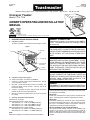
I. DESCRIPTION AND SPECIFICATIONS
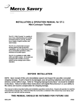
A. Component Location
The major components of the toaster are shown in Figure 1 below.
6. Return tray
1. Product
selection knob
5. Conveyor
2. Conveyor speed
control knob
B. Component Function (see Figure 1)
1-2. Toaster control knobs - see Section III, Operation.
3. Crumb tray - Collects crumbs from the toasted product. The tray
can be removed for cleaning.
4. Entry rack - Loaded with the bakery product to be toasted. The
product then slides onto the conveyor. The entry rack can be
removed for cleaning.
5. Conveyor - Transports the bakery product through the toaster,
between the top and bottom heating elements.
6. Return tray - Collects the toasted product. The tray can be removed
for cleaning.
C. Operating and Electrical Specifications
Pre-Heat Time: 20 minutes
Electrical Specifications/TC14 toaster models:
120V, 50/60 Hz, 1 Ph, 1.7kW, 14.3A, NEMA 5-20P plug
208V, 50/60 Hz, 1 Ph, 2.1kW, 10.2A, NEMA 6-15P plug
240V, 50/60 Hz, 1 Ph, 2.1kW, 8.8A, NEMA 6-15P plug
Electrical Specifications/TC18 toaster models:
208V, 50/60 Hz, 1 Ph, 2.65kW, 12.8A, NEMA 6-20P plug
240V, 50/60 Hz, 1 Ph, 2.65kW, 11.1A, NEMA 6-20P plug
NOTE
Electrical wiring diagrams are provided at the back of this Manual.
Figure 1
Conveyor Toaster
Models TC14, TC18
OWNER'S OPERATING AND INSTALLATION
MANUAL
3. Crumb tray
4. Entry rack

II. INSTALLATION
IMPORTANT
IT IS THE CUSTOMERS RESPONSIBILITY TO REPORT ANY
CONCEALED OR NON-CONCEALED DAMAGE TO THE FREIGHT
COMPANY.
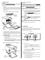
A. Assembly
1. Thread the 4 (102mm) legs into the four holes on the bottom of the
toaster. See Figure 2. Then, place the toaster in the desired location.
2. Install the entry rack and crumb tray into the front of the toaster, as
shown in Figure 2.
Figure 2 - Basic assembly and front-exit configuration
Legs (4)
thread into holes
in bottom of
toaster
Entry rack
hanger rods fit
into holes on
toaster body
Crumb tray
slides into opening
in front of toaster
Return tray
slides underneath
toaster
Figure 3 - Electrical connection and rear-exit configuration
3. TOASTERS INTENDED FOR FRONT-EXIT OPERATION ONLY:
Position the return tray underneath the toaster, as shown in Figure
2. Note that the return tray extends past the FRONT of the toaster
during front-exit operation.
4. TOASTERS INTENDED FOR STRAIGHT-THROUGH, REAR-
EXIT OPERATION ONLY:
Remove the CENTER screw from the rear panel of the toaster,
as shown in Figure 3.
Push the rear panel forward into the toaster.
Position the return tray underneath the toaster as shown in
Figure 3. Note that the return tray extends past the REAR of
the toaster during rear-exit operation.
2. Adjust
panel
1. Remove
screw
Return tray
slides underneath
toaster
B. Electrical Utility Connection
IMPORTANT
THE ELECTRICAL CONNECTION TO THE TOASTER REQUIRES A
CIRCUIT BREAKER/FUSED DISCONNECT. ELECTRICAL SPECIFI-
CATIONS ARE LISTED ON THE SERIAL PLATE (SHOWN IN FIGURE
3), AND IN THE ELECTRICAL SPECIFICATIONS ON PAGE 1 OF THIS
MANUAL.
CONSULT ALL APPLICABLE NATIONAL AND LOCAL CODES FOR
FURTHER ELECTRICAL CONNECTION REQUIREMENTS.
1. Before proceeding with the electrical connection, check the following:
a. Check that the electrical supply matches the toasters
requirements. Refer to the toasters serial plate (Figure 3)
and to the Electrical Specifications on Page 1.
b. Check that the appropriate receptacle is available for the power
cord plug.
WARNING
ENSURE THAT BOTH THE CIRCUIT BREAKER/FUSED DIS-
CONNECT AND THE PRODUCT SELECTION KNOB ARE IN
THE OFF (0) POSITION BEFORE PROCEEDING.
WARNING
ENSURE THAT ANY PACKING MATERIAL RESIDUE HAS
BEEN REMOVED FROM INSIDE THE TOASTING CHAMBER.
3. Insert the power cord plug into its receptacle.
Serial plate
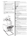
III. OPERATION
A. Location and Function of Controls
This section provides a basic description of the toaster controls, their
location, and the functions they perform. The operator MUST be familiar
with the controls. Refer to Figure 4.
Figure 4
1. Product
selection knob
2. Conveyor
speed control
knob
1. Product Selection knob
When set to TOAST ( ), switches on the conveyor, the
upper heating element, and one lower heating element.
When set to OFF (O), switches off the conveyor and all heating
elements.
When set to BUNS/BAGELS ( ), switches on the conveyor
and both of the lower heating elements.
2. Conveyor Speed Control knob
Adjusts the speed of the conveyor. This controls the amount of
toasting that the bakery product receives.
1 is the minimum speed setting, which produces a darker
toasting of the bakery product.
9 is the maximum speed setting, which produces a lighter
toasting of the bakery product.

C. Shutdown Procedure
1. Switch the Product Selection knob to the OFF (O) position.
2. Disconnect electrical power to the toaster at the circuit breaker/
fused disconnect.
3. Allow the toaster to cool.
D. Clearing Jams
WARNING
NEVER INSERT YOUR HANDS INTO THE TOASTING CHAM-
BER TO CLEAR A JAM. SERIOUS INJURY MAY RESULT.
CAUTION
NEVER use a plastic object to clear a jam. If the toaster is not com-
pletely cool, damage to the toaster may result.
CAUTION
When clearing a jam, use care to avoid damaging the heating elements.
1. Switch the Product Selection knob to the OFF (O) position.
2. Disconnect electrical power to the toaster at the circuit breaker/
fused disconnect.
3. Allow the toaster to cool.
CAUTION - HOT SURFACES
DO NOT ATTEMPT TO CLEAR THE JAM UNTIL THE TOASTER
HAS COOLED THOROUGHLY.
4. Carefully clear the jam using a long object as a probe. This object
should preferably be made of wood, which is less likely to damage
the heating elements.
E. Daily Cleaning
WARNING
WHEN CLEANING THE TOASTER, NEVER APPLY ENOUGH
LIQUID TO STAND IN PLACE ON THE UNIT. DO NOT SPRAY,
RINSE, OR SUBMERGE THE TOASTER. EXCESSIVE MOIS-
TURE IN THE UNIT WILL CAUSE A SEVERE ELECTRICAL
HAZARD AND MAY OTHERWISE DAMAGE THE TOASTER.
CAUTION
DO NOT clean your toaster using abrasive cleaners or pads. Both will
scratch and dull the finish.
1. With the conveyor running, use a brush to clean any crumbs off the
conveyor into the crumb tray.
2. Switch the Product Selection knob to the OFF (O) position.
3. Disconnect electrical power to the toaster at the circuit breaker/
fused disconnect.
4. Allow the toaster to cool.
CAUTION - HOT SURFACES
DO NOT TOUCH HOT SURFACES ON THE TOASTER, OR
REACH INTO THE TOASTING CHAMBER, UNTIL THE UNIT
HAS COOLED THOROUGHLY.
5. Wipe the exterior of the toaster with a sponge or cloth soaked in hot
or warm detergent water. Wipe with a clean, damp cloth to remove
the excess detergent, and then wipe again to dry the toaster.
6. Remove the crumb tray and the return tray from the toaster, and
empty them. Wash the trays in warm detergent water, and rinse
them.
CAUTION
Never remove the crumb tray while the conveyor is moving.
7. Remove the entry rack from the toaster. Wash the rack in warm
detergent water, and rinse it.
8. Towel the trays and entry rack dry. Reassemble all parts onto the
toaster.
Load buns/bagels
CUT SIDE DOWN
for proper toasting
Product selection
knob in BUNS/
BAGELS position
Figure 5
B. Operation Procedure
1. Restore electrical power to the toaster at the circuit breaker/fused
disconnect.
2. Switch the Product Selection knob to either TOAST ( ) or BUNS/
BAGELS ( ), depending on the product to be toasted.
3. Allow the toaster to pre-heat for at least 20 minutes.
4. Adjust the toasting time (if necessary) by turning the conveyor speed
control knob.
5. Load the entry rack with the bakery product to be toasted. The
product will slide off the entry rack and onto the conveyor.
IMPORTANT
If the Product Selection knob is set to BUNS/BAGELS ( ), load
the bakery product CUT SIDE DOWN for proper toasting. Refer to
Figure 5.
6. After toasting, remove the product from the return tray.
7. During inactive periods, switch the Product Selection knob to the
BUNS/BAGELS ( ) position. This leaves only the lower heating
elements on, allowing a quicker recovery to normal toasting
temperatures.

A Middleby Company
Toastmaster 1400 Toastmaster Drive Elgin, IL 60120 USA (847)741-3300 FAX (847)741-4406
Middleby Corp 24-Hour Service Hotline 1-800-238-8444
www.middleby.com
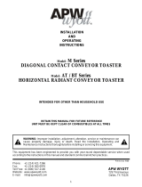
Wiring Diagram
Model TC14 120V
Toasters
Wiring Diagram
Model TC14 208V
and 240V Toasters
Wiring Diagram
Model TC18 208V
and 240V Toasters
Switch
Configuration
All Model TC14 and
TC18 Toasters
TOP ELEMENT
BTM ELEMENT 1
BTM ELEMENT 2
CONVEYOR
SPEED
CONTROL
PRODUCT
SELECTION
SWITCH
TERMINAL
BLOCK
GND
MOTOR
FAN
FUSE
RED
BLACK
TOP ELEMENT
BTM ELEMENT 1
BTM ELEMENT 2
CONVEYOR
SPEED
CONTROL
PRODUCT
SELECTION
SWITCH
TERMINAL
BLOCK
GND
MOTOR
FAN
FUSE
RED
BLACK
TRANSFORMER
230V p
115V s
CONVEYOR
SPEED
CONTROL
PRODUCT
SELECTION
SWITCH
TERMINAL
BLOCK
GND
MOTOR
FAN
FUSE
RED
BLACK
TRANSFORMER
230V p
115V s
TOASTOFF
BUNS/
BAGELS
TOP ELEMENT
BTM ELEMENT 1
BTM ELEMENT 2
-
 1
1
-
 2
2
-
 3
3
-
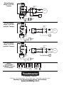 4
4


Toastmaster TC-14 User manual
- Category
- Toasters
- Type
- User manual
Ask a question and I''ll find the answer in the document
Finding information in a document is now easier with AI
Related papers
-
Toastmaster TC18A User manual
-
-
-
-
Toastmaster TB240 User manual
-
-
-
-
-
Other documents
-
 Merco Savory Toaster ST-1 User manual
-
Middleby Marshall TC18 User manual
-
Hatco TOAST-QWIK TQ-10 Series Installation guide
-
 APW Wyott M-95-2 User manual
-
-
Star HCT13 Owner's manual
-
Vollrath Toaster, Conveyor, Model JT2/JT2H/JT3/JT3H User manual
-
-
-
Merco RT-2T User manual

