Page is loading ...

L8542518
06/2012 rev 3
CP.ZED230-E
UNIONE NAZIONALE COSTRUTTORI
AUTOMATISMI PER CANCELLI, PORTE
SERRANDE ED AFFINI

3
230Vac
50Hz
L
N
COM
24Vac
1A max
AUX
ANT
SHIELD
ANT
1
2
GND
3
4
5
6
7
8
17
18
19
20
21
22
23
24
LAMP.
230VAC
Light Service
Light Service
M2
M1
8k2
DAS
SWO
SWC
STOP
PHOT
OPEN
COM
CLOSE
P.P.
9
10
11
12
13
14
15
16
M2 M1
12
GND
U5
ENCODER
F2
230V:F5A
115V:F10A
RADIO
F1
315mA
CM CM
1

4
2
3
)!'
%(+!
)!'
%(+!
24Vac 24Vac
COM
NC
RX TX
17
18
19
20
9
10
11
12
13
14
15
16
17
18
19
20
SCA
3W max
19
20
N.O.
AUX:0
17
18
19
20
AUX:3
AUX:1
AUX:2
24Vac
1A max
PHOT
COM
L N
Service Light
230Vac
Relè
24Vac
LAMP
24 Vdc
17
18
19
20
AUX:4
SCA II° CH RADIO
PHOTO TEST
LAMP SERVICE LIGHT

12
WARNINGS
This manual has been especially written to be use by
qualified fitters.
None of the information provide in this manual can be
considered as being of interest for the end users.
Preserve this manual for future needs.
The technician has to furnish all the information related to
the step by step function, the manual and the emergency
function of the operator, and to deliver the manual to the
final user.
;
Foresee on the supply net an onnipolar switch or
selector with distance of the contacts equal or
superior to 3 mms.
Verify that of the electrical system there is an awry diffe-
rential interrupter and overcurrent protection.
Some typologies of installation require the connection of
the shutter to be link at a conductive mass of the ground
according to the regulations in force.
The electrical installation and the operating logic must
comply with the regulations in force.
The leads fed with different voltages must be physically
separate, or they must be suitably insulated with additional
insulation of at least 1 mm.
The leads must be secured with an additional fixture near
the terminals.
During installation, maintenance and repair, interrupt the
power supply before opening the lid to access the elec-
trical parts
Check all the connections again before switching on the
power.
The unused N.C. inputs must be bridged.
The descriptions and the present illustrations in this manual
are not binding. Leaving the essential characteristics of the
product unchanged, the manufacturer reserves himself
the right to bring any change of technical, constructive
or commercial character without undertaking himself to
update the present publication.
EC Declaration of conformity
Declaration pursuant to Directives 2004/108/EC(EMC); 2006/95/EC(LVD)
Manufacturer:
Automatismi Benincà SpA
Address:
Via Capitello, 45 - 36066 Sandrigo (VI) - Italy
Declares that the product:
Control unit CP.ZED230-E
is compliant with the conditions of the following EC Directives:
• DIRECTIVE 2004/108/EC OF THE EUROPEAN PARLIAMENT AND COUNCIL of December 15 2004 regarding
the approximation of the legislations of the member States relative to electromagnetic compatibility and that repeals directive
89/336/CEE, according to the following concurred norms:
EN 61000-6-2:2005, EN 61000-6-3:2007.
• DIRECTIVE 2006/95/EC OF THE EUROPEAN PARLIAMENT AND THE COUNCIL of December 12 2006 concer-
ning the approximation of the legislations of the member States relative to electrical material destined to be used within certain
voltage limits, according to the following concurred regulations:
EN 60335-1:2002 + A1:2004 + A11:2004 + A12:2006 + A2:2006 + A13:2008; EN 60335-2-103:2003.
if applicable :
• DIRECTIVE 1999/5/EC OF THE EUROPEAN PARLIAMENT AND THE COUNCIL of March 9 1999 regarding radio
devices and terminal and telecommunications devices and the reciprocal recognisances of their conformity, according to the
following concurred regulations: ETSI EN 301 489-3 V1.4.1 (2002) + ETSI EN 301 489-1 V1.4.1 (2002) + ETSI EN 300 220-3
V1.1.1 (2000) + EN 60950-1 (2001)
Benincà Luigi, Legal manager.
Sandrigo, 02/11/2010.

13
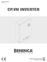
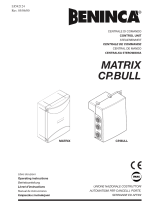
CP.ZED230-E CONTROL UNIT
WIRE DIAGRAM
Wire connections shown in Fig. 1 are described hereunder:
Terminal No. Function Description
1-2 Power supply Input, 230VAC 50Hz (1-Phase/2-Neutral)
3-4 Flashing light Connection of flashing light, 230Vac 40W max.
4-5 Motor light Connection to the courtesy light (230VAC 40+40W max.).
6-7-8 Motor 1/2
Connection to motor 1/2 : (6-speed/7-Com/8-speed)*
Should 2 motors be used, connect the second motor in parallel.
9 COM Common for limit switch and all control inputs.
10 SWO Input, OPEN limit switch (N.C. contact)
11 SWC Input, CLOSE limit switch (N.C. contact)
12 STOP Input, STOP push button (N.C. contact)
13 PHOT
Input, connection to safety devices, N.C. contact
(e.g. Photocells)
14 OPEN Input, OPEN push button (N.O. contact)
15 CLOSE Input, CLOSE push button (N.O. contact)
16 Step-by-Step Input, step-by-step push button (N.O. contact)
17-18 24 Vac Output, power supply of accessories, 24Vac/1A max.
19-20 AUX Normally Open (N.O.) contact, not powered, configurable as SCA/II°CH/PHOTO TEST.
21-22 COSTA
Input, safety edge contact
Resistive edge: Closed “DAS” jumper
Mechanical edge: Open “DAS” jumper
If the safety edge is activated in the opening phase, the gate stops.
In the closing phase, the gate stops and the performs a movement reversion (opens) for 3s.
23-24 Aerial Connection to the radio receiver card of the aerial (23-screen/24-signal).
CM-CM Capacitor Connected to motor capacitor
J3 Radio receiver Built-in radio receiver
IMPORTANT:
Should two motors be used, connect the limit switches of one single motor to the control unit.
The connection between CP.ZED230-E and the ZED.SC card is shown in Fig.3.
FUSES
F1 Output protection fuse of accessories and signals
F2 Motor protection fuse
PROGRAMMING
The programming of the various functions of the control unit is carried out using the LCD display on the control unit and setting the
desired values in the programming menus described below.
The parameters menu allows you to assign a numerical value to a function, in the same way as a regulating trimmer.
TECHNICAL DATA
Contol unit supply
230 Vac 50/60 Hz or 115Vac 50/60Hz according to the version
Output supply
1/2 motor 230Vac
Power maximum motor
300+300 W
Output supply accessories
24Vac 1Amax.
Protection level
IP54
Operating temp.
-20°C / +70°C
Radio receiver
built in 433,92 MHz confgurabile (rolling-code or programmable + rolling-code)
Rolling code transmitters supported
64 rolling-code

14
The logic menu allows you to activate or deactivate a function, in the same way as setting a dip-switch.
Other special functions follow the parameters and logic menus and may vary depending on the type of control unit or the software
release.
USE OF PROGRAMMING KEYS
Press <PG> key to gain access to the Main Menu. These keys can be selected by pressing # and $ keys.
t*G#> is pressed, the Function Menu can be scrolled from top to bottom.
t*G$> is pressed, the Function Menu can be scrolled from bottom to top.
t*G1(LFZJTQSFTTFEQSFTFUUJOHUPCFNPEJmFEDBOCFFOUFSFE
t5IFQSFTFUWBMVFTDBOCFNPEJmFECZVTJOH#> and <$> keys.
t5IFWBMVFJTQSPHSBNNFEJG1(LFZJTQSFTTFEBHBJO5IFXPSEi13(wBQQFBSTPOUIFEJTQMBZ
See paragraph “Programming Example”.
NOTES:
Simultaneously pressing <#> and <$> from inside a function menu allows you to return to the previous menu without making any
changes.
If the push-button <$> is pressed with display off, this is like giving a step-by-step control.
When the board is switched on, the software version is displayed for around 5 sec
Hold down the <#> key or the <$> key to accelerate the increase/decrease of the values.
After waiting 60s the control unit quits programming mode and switches off the display.
PARAMETERS, LOGICS AND SPECIAL FUNCTIONS
In the tables hereunder the single functions available in the control unit are shown.
PARAMETERS (PAR)
MENU FUNCTION
MIN-MAX-(Default)
MEMO
TCA
Automatic closure time. It is activated only with “TCA”=ON logic.
At the end of the preset time, the control unit controls a closure operation.
1-240-(40s)
TM
Motor operating time. The total stroke time in the motor opening and closing phases
is adjusted.
With the ENC:ON logics, this value is automatically preset by the parameter self-
adjustment procedure (AUTO).
2-180-(60s)
Tsm
The space covered by the dooe leaf during braking in the closing phase is adjusted.
Braking in the opening phase is automatically preset at 1/4 of the closing space.
0 = braking is disabled.
With ENC:OFF logics the value is expressed in seconds. Braking after the triggering of
the limit switch is adjusted.
0-99-(10%)
PMo
The torque applied to the motor in the opening phase is adjusted.* 1-99-(40%)
PMC
The torque applied to the motor in the closing phase is adjusted *. 1-99-(40%)
Pso
The torque applied to the motor during braking in the closing phase is adjusted.* 1-99-(40%)
Psc
The torque applied to the motor during braking in the opening phase is adjusted * 1-99-(40%)
TLS
The activation time of the service light is adjusted.
With parameter :0, the area light function is activated. The light is switched on when
the motor is moving and during the TCA dwell time. The light switches off when the
motor stops.
0-240-(60s)
SEAV
The triggering threshold of the anti-crash device (Encoder) during the normal speed
phase.*
99: maximum sensitivity - 0: minimum sensitivity
0-99-(0%)
SEAR
The triggering threshold of the anti-crash device (Encoder) during braking.*
99: maximum sensitivity - 0: minimum sensitivity
0-99-(0%)
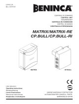
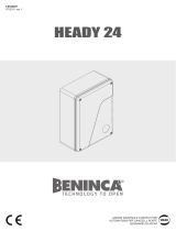
AUX
The operating mode of the auxiliary output to terminals 19/20 is preset. See wire con-
nections in figure 2.
0: output configurated as SCA (open gate indicator light): Off with closed door, on
with open door, slow flash during opening, rapid flash during closing.
1: output configurated as radio channel II integrated receiver.
2: output configurated as PHOT TEST (photocell test).
3: output configurated as flashing light.
4: output configurated as service light additional to the light on the geared motor. Its
activation time is adjusted by TLS parameter.
0-4-(0)
* WARNING:
An incorrect setting of these parameters may cause danger.
Please comply with regulations in force!

15
LOGIC (LOG)
MENU FUNCTION
ON-OFF-
(Default)
MEMO
TCA
The automatic closure is enabled or disabled
On: enabled automatic closure
Off: disabled automatic closure
(OFF)
IbL
The multi-flat function is enabled or disabled.
On: enabled multi-flat function. The P.P. (Step-by-step) impulse or the impulse of the tran-
smitter have no effect in the opening phase.
Off: disabled multi-flat function.
(OFF)
PP
The operating mode of “P.P. Push button” and of the transmitter are selected.
On: Operation : OPEN > CLOSE > OPEN >
Off: Operation: OPEN > STOP > CLOSE > STOP >
(OFF)
PRE
Forewarning flashing light enabled or disabled.
On: enabled forewarning flashing light. The flashing light is activated 3 s before the starting of
the motor.
Off: disabled forewarning flashing light.
(OFF)
blc
The lock function in the closing phase is enabled or disabled.
See paragraph “Operating mode with Enabled/Disabled encoder”.
On: Lock function is enabled.
Off: Lock function is disabled.
(ON)
ltca
During the TCA time, the blinker is enabled or disabled.
On: Activated blinker.
Off: De-activated blinker.
(OFF)
spn
The pick-up function with ENC:OFF logics is activated or deactivated.
On: the function is enabled. The first two seconds of operation are carried out at maximum
torque.
With ENC:ON logics, pick-up is automatically adjusted by the control unit.
(OFF)
htr
The Operator function is enabled or disabled.
On: Operator function enabled.
During operation, the OPEN/CLOSE push-buttons must be kept pressed.
Off: Automatic/semiautomatic operation.
(OFF)
IBCA
During the TCA phase, the PP and PED controls are enabled or disabled.
On: PP and PED controls are disabled.
Off: PP and PED controls are enabled.
(OFF)
ENC
The Encoder is enabled or disabled.
On: Enabled encoder.
Off: Disabled encoder (to be used with ZED series motors that are not equipped with built-in
Encoder).
NB: The Encoder can be possibly reset (from OFF to ON). A new self-calibration procedure is
required (AUTO menu).
(ON)
CVAR
The code programmable transmitters is enabled or disabled.
On: Radio receiver enabled only for rolling-code transmitters.
Off: Receiver enabled for rolling-code and programmable code transmitters (self-learning and
Dip Switch).
(OFF)
PHTo
The operating mode of the PHOT input is selected.
On: PHOT input is activated in both opening and closing.
In the opening phase: when the contact is opened, the motor stops. When the photocell is
released, the motor restarts with an opening movement.
In the closing phase: when the contact is opened, the motor stops. When the photocell is
released, the motor inverts its movement direction (opens).
Off: PHOT input is activated only in the closing phase.
In the closing phase: when the contact is opened, the motor stops and the movement direc-
tion is immediately reversed (opens).
(OFF)
rem
The remote storage of the radio transmitter codes is enabled or disabled (see par. REMOTE
LEARNING).
On: Enabled remote storage
Off: Disabled remote storage.
(OFF)

16
RADIO (RAD)
MENU FUNZIONE
PP
By selecting this function, the receiver awaits (Push) for a transmitter code to be assigned to the step-by-step fun-
ction.
Press the transmitter key to be assigned to this function.
If the code is valid, it is stored in memory and OK appears.
If the code is not valid, the wording Err is displayed.
2Ch
With AUX:1 parameter, the radio channel II function to terminals 19/20 is activated.
With AUX:0 e AUX:2 parameter, the service light is activated according to the time preset by TLS parameter.
By selecting this function, the receiver awaits (Push) the pressure of the key to be matched with that function.
If the code is valid, the same is memorised and the OK message is displayed.
If the code is not valid, the Err message is displayed.
CLR
By selecting this function, the receiver awaits (Push) for a transmitter code to be erased from memory.
If the code is valid, it is erase and OK appears.
If the code is not valid or is not in memory, the wording Err is displayed.
RTR
Completely erase the receiver memory. Confirmation of operation is required.
CYCLES NUMBER (Nman)
Displays the number of complete cycles (open+close) carried out by the automation.
When the <PG> button is pressed for the first time, it displays the first 4 figures, the second time it shows the last 4. Example <PG>
0012 >>> <PG> 3456: made 123.456 cycles.
MAINTENANCE CYCLES (maci)
This function enables to activate the maintenance request notice after a number of manoeuvres determined by the installer.
To activate and select the number of manoeuvres, proceed as follows:
Press button <PG>, the display will show OFF, which indicated that the function is disabled (default value).
With the buttons <+> and <-> select one of the numeric values proposed (from OFF to 100). The values are intended as hundreds
of cycles of manoeuvres (for example: the value 50 indicates 5000 manoeuvres).
Press the OK button to activate the function. The display will show the message PROG.
The maintenance request is indicated to the user by keeping the indicator lamp lit up for other 10 sec after the conclusion of the
opening or closing operation.
The warning of maintenance required is indicated to the user through the flashing of the courtesy light LEDs during the opening and
closing phases.
RESET (RES)
RESET of the control unit. ATTENTION!: Returns the control unit to the default values.
Pressing the <PG> button for the first time causes blinking of the letters RES, pressing the <PG> button again resets the control
unit. Note: The transmitters are not erased from the receiver nor is the access password.
PROTECTION CODE (CODE)
It allows to type in an access protection code to the programming of the control unit.
A four-character alphanumeric code can be typed in by using the numbers from 0 to 9 and the letters A-B-C-D-E-F.
The default value is 0000 (four zeros) and shows the absence of a protection code.
While typing in the code, this operation can be cancelled at any moment by pressing keys + and – simultaneously. Once the pas-
sword is typed in, it is possible to act on the control unit by entering and exiting the programming mode for around 10 minutes in
order to allow adjustments and tests on functions.
By replacing the 0000 code with any other code, the protection of the control unit is enabled, thus preventing the access to any
other menu. If a protection code is to be typed in, proceed as follows:
- select the Code menu and press OK.
- the code 0000 is shown, also in the case a protection code has been previously typed in.
- the value of the flashing character can be changed with keys + and -.
- press OK to confirm the flashing character, then confirm the following one.
- after typing in the 4 characters, a confirmation message “CONF” appears.
- after a few seconds, the code 0000 appears again
- the previously stored protection code must be reconfirmed in order to avoid any accidental typing in.
If the code corresponds to the previous one, a confirmation message “OK” appears.
The control unit automatically exits the programming phase. To gain access to the Menus again, the stored protection code must
be typed in.
IMPORTANT: TAKE NOTE of the protection code and KEEP IT IN A SAFE PLACE for future maintenance operations.
To remove a code from a protected control unit it is necessary to enter into programming with the password and
bring the code back to the 0000 default value.
IF YOU LOOSE THE CODE, PLEASE CONTACT THE AUTHORISED SERVICE CENTER FOR THE TOTAL RESET OF THE CON-
TROL UNIT.

17
INSTALLATION
The CP.ZED230E control unit can be used with various versions of the ZED gear motor:
ZED with 2 limit switches (opening an closing).
ZED with 1 limit switch (usually used as opening limit switch or auxiliary operations)
ZED without limit switch
If one or more limit switch are missing, the operation stop is controlled by the control unit after memorizing the opening/closing posi-
tions.
The following procedure shall apply for all versions:
1) Power the control unit
2) Manually unlock and completely close the door.
3) If provided, adjust the closing limit switch cam, the SWC display segment switches on (see section “Diagnostics”). If the
SWO segment switches on, invert the SWO<>SWC limit switch wires.
4) Move the door into the desired open position. Provide for some overrun centimetre.
5) If provided, adjust the opening limit switch cam. The SWO display segment switches on.
6) Lock the door again.
7) Start a self-test operation:
- Press PGM, select the AUTO Menu with push-buttons <#> and <$> il menu AUTO.
- Press PGM, the word AUTO starts flashing.
- Press PGM agaom, the word “UP” is displayed.
- If the door is not in the desired position, press and keep the <#> to open the door or <$> to sjut the door, release the push-
button in the opening position to be stored in memory .
Note:
- if, by pressing <#>, the door closes, this means that the connection to the motor is incorrect. Therefore invert the opera-
tion wires (6<>8) and repeat the procedure from item 7.
- the opening potizion can be adjusted in the SERVICE MAN mode; therefore, all safety devices are de-activated. A previou-
sly memorized transmitter can be used as an alternative to push-buttons <#> and <$>.
- Press PGM again to start the self-learning procedure. The PRG message is displayed. The control unit controls a total clo-
sure operation, followed by an opening and closing operation.
- At end of procedure, the message OK is displayed.
NB.: If the “ERR” error message appears during the self-test phase, see section “Error messages”.
Exit the programming mode by pressing keys <#> and <$> simultaneously, or by waiting for 30 seconds (time-out).
OPERATING MODE WITH ENABLED/DISABLED ENCODER
With ENC=ON LOGICS:
- the anti-crash sensor is activated. The sensitivity must be adjusted through the SEAV and SEAR parameters according to regula-
tions in force.
Once the stroke length is stored in memory by the control unit, the latter will automatically manage the braking phases during opening
and closing. The braking space can be increased or decreased by the TSM parameter. The stroke is constantly updated and stored in
memory together with the gate position in the event of power failure.
If the BLOC logics is ON, after the TSM braking time has elapsed, the stop will be delayed by around 1s when the limit switch is trig-
gered.
With the ENC=OFF LOGICA (To be used with motors without encoder):
- the anti-crash sensor is deactivated.
- if the parameter TSM>0 (braking activated), the control unit starts the braking phase after triggering the limit switch. Duration is
preset through the parameter itself.
NB: Preset the TM parameter for a value higher than the stroke time.
In this position, the BLOC logics is irrelevant.
TRANSMITTER REMOTE LEARNING
If the transmitter code is already stored in the receiver, the remote radio learning can be carried out (without accessing the control
unit).
IMPORTANT: The procedure should be carried out with gate in the opening phase, during the TCA dwell time.
Proceed as follows:
1 Press the hidden key of the transmitter, the code of which has already been stored in memory.
2 Within 5 seconds, press the already memorised transmitter key corresponding to the channel to be matched to the new transmitter.
The flashing light switches on.
3 Within 10 seconds, press the hidden key of the new transmitter.
4 Within 5 seconds, press the key of the new transmitter to be matched to the channel selected at item 2. The flashing light switches
off.
5 The receiver stores the new transmitter code and exits from the programming mode immediately.

18
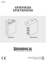
DIAGNOSTICS
One segment of the display is linked to each input. In the event of failure it switches on
according to the following scheme.
N.C. inputs are represented by the vertical segments. N.O. inputs are represented by the
horizontal segments.
SWC
STOP
SWO
PHOT
DAS
P.P. OPEN CLOSE
ERROR MESSAGES
The control unit checks the correct operation of the safety devices. In the event of failure, the following messages may be displayed:
ERR Error, self-learning stroke:
- activation of any input by the user
- door leaf i the closing limit switch
- HTR:ON logics
- memorisation of remote controls
ERR1 Check of management circuit integrity has failed
ERR2 Error, PHOTO TEST
ERR3 Encoder is broken.
WASTE DISPOSAL
If the product must be dismantled, it must be disposed according to regulations in force regarding the differentiated waste disposal
and the recycling of components (metals, plastics, electric cables, etc..). For this operation it is advisable to call your installer or a
specialised company.

AUTOMATISMI BENINCÀ SpA - Via Capitello, 45 - 36066 Sandrigo (VI) - Tel. 0444 751030 r.a. - Fax 0444 759728
/