Page is loading ...

CAM44-IO-16s.book Seite 2 Mittwoch, 5. Oktober 2016 11:38 11

CAM44
3
1 2 3
4
9
6
8
5
7
10 11
12
1
CAM44-IO-16s.book Seite 3 Mittwoch, 5. Oktober 2016 11:38 11
Page is loading ...

CAM44
5
Ø 16 mm
1
2
3
4
5
6
7
V2
V1
TWIN
8
4
3
2
1
5
9
2.
1.
1.
0
CAM44-IO-16s.book Seite 5 Mittwoch, 5. Oktober 2016 11:38 11
Page is loading ...

CAM44
7
90°
d
e
f
g
CAM44-IO-16s.book Seite 7 Mittwoch, 5. Oktober 2016 11:38 11

CAM44
8
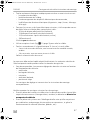
h
i
j
k
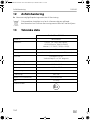
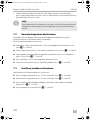
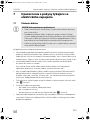
~20°
l
CAM44-IO-16s.book Seite 8 Mittwoch, 5. Oktober 2016 11:38 11

CAM44
9
A
B
m
9102200078
V 2
V 1
TWIN
n
CAM44-IO-16s.book Seite 9 Mittwoch, 5. Oktober 2016 11:38 11

CAM44
10
AMP100
Monitor (RCA)
Camera Input
12 - 24V
o
A
B
C
p
CAM44-IO-16s.book Seite 10 Mittwoch, 5. Oktober 2016 11:38 11

EN
CAM44
11
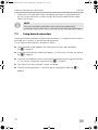
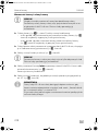
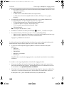
Please read this instruction manual carefully before installation and first
use, and store it in a safe place. If you pass on the product to another
person, hand over this instruction manual along with it.
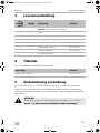
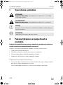
Contents
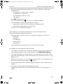
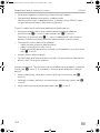
1 Explanation of symbols . . . . . . . . . . . . . . . . . . . . . . . . . . . . . . . . . . . . . . . . . .12
2 Safety and installation instructions . . . . . . . . . . . . . . . . . . . . . . . . . . . . . . . . .12
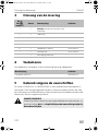
3 Scope of delivery . . . . . . . . . . . . . . . . . . . . . . . . . . . . . . . . . . . . . . . . . . . . . .15
4 Accessories . . . . . . . . . . . . . . . . . . . . . . . . . . . . . . . . . . . . . . . . . . . . . . . . . . .15
5 Intended use . . . . . . . . . . . . . . . . . . . . . . . . . . . . . . . . . . . . . . . . . . . . . . . . . .15
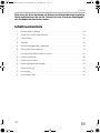
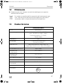
6 Technical description . . . . . . . . . . . . . . . . . . . . . . . . . . . . . . . . . . . . . . . . . . .16
7 Notes on the electrical connections . . . . . . . . . . . . . . . . . . . . . . . . . . . . . . .17
8 Fitting the camera . . . . . . . . . . . . . . . . . . . . . . . . . . . . . . . . . . . . . . . . . . . . . 20
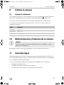
9 Using the camera . . . . . . . . . . . . . . . . . . . . . . . . . . . . . . . . . . . . . . . . . . . . . 26
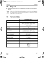
10 Cleaning and caring for the camera. . . . . . . . . . . . . . . . . . . . . . . . . . . . . . . 26
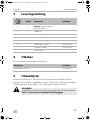
11 Guarantee . . . . . . . . . . . . . . . . . . . . . . . . . . . . . . . . . . . . . . . . . . . . . . . . . . . 26
12 Disposal. . . . . . . . . . . . . . . . . . . . . . . . . . . . . . . . . . . . . . . . . . . . . . . . . . . . . 27
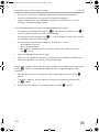
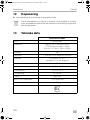
13 Technical data . . . . . . . . . . . . . . . . . . . . . . . . . . . . . . . . . . . . . . . . . . . . . . . . 27
CAM44-IO-16s.book Seite 11 Mittwoch, 5. Oktober 2016 11:38 11

EN
Explanation of symbols CAM44
12
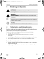
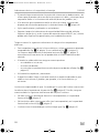
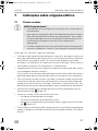
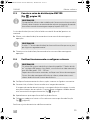
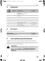
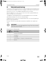
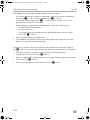
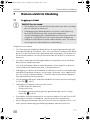
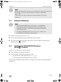
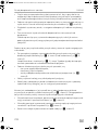
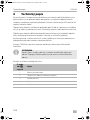
1 Explanation of symbols
!
!
A
I
2 Safety and installation instructions
Please observe the prescribed safety instructions and stipulations from the
vehicle manufacturer and service workshops.
The manufacturer accepts no liability for damage in the following cases:
• Faulty assembly or connection
• Damage to the product resulting from mechanical influences and excess voltage
• Alterations to the product without express permission from the manufacturer
• Use for purposes other than those described in the operating manual
Please observe the following instructions:
• To prevent short circuits, always disconnect the negative terminal of the vehicle’s
electrical system before working on it.
If the vehicle has an additional battery, its negative terminal should also be dis-
connected.
• Insufficient supply line connections could result in short circuits which
–Cause cable fires
– Trigger the airbags
– Damage electronic control devices
– Cause electric functions to fail (indicators, brake light, horn, ignition, lights)
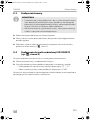
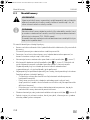
WARNING!
Safety instruction: Failure to observe this instruction can cause fatal or
serious injury.
CAUTION!
Safety instruction: Failure to observe this instruction can lead to injury.
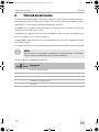
NOTICE!
Failure to observe this instruction can cause material damage and impair
the function of the product.
NOTE
Supplementary information for operating the product.
CAM44-IO-16s.book Seite 12 Mittwoch, 5. Oktober 2016 11:38 11

EN
CAM44 Safety and installation instructions
13
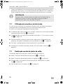
• When working on the following cables, only use insulated cable terminals, plugs
and flat push-on receptacles:
– 30 (direct supply from positive battery terminal)
– 15 (connected positive terminal, behind the battery)
– 31 (return cable from the battery, earth)
– 58 (reversing light)
Do not use terminal strips.
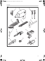
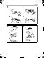
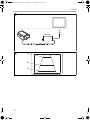
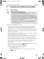
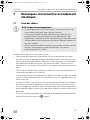
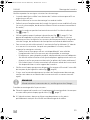
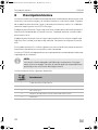
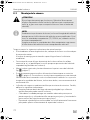
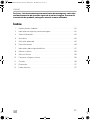
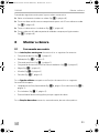
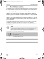
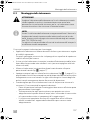
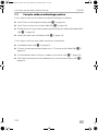
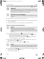
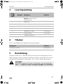
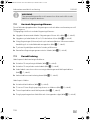
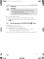
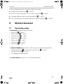
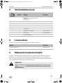
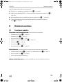
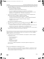
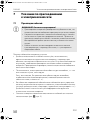
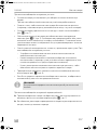
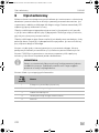
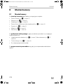
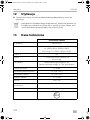
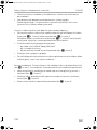
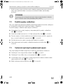
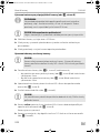
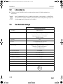
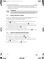
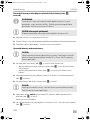
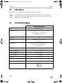
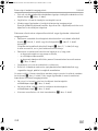
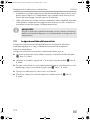
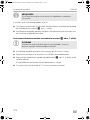
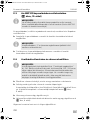
• Use a crimping tool (fig. 1 10, page 3) to connect the cables.
• Screw the cable for connections to cable 31 (earth)
– Screw on the cable using a cable terminal and serrated washer to one of the
vehicle's earth bolts or
– Screw the cable to the bodywork using a cable terminal and a self-tapping
screw
Make sure there is a good earth connection.
If you disconnect the negative terminal of the battery, the entire data stored in the
volatile memories will be lost.
• The following data must be reset, depending on the vehicle equipment options:
–Radio code
– Vehicle clock
–Timer
– On-board computer
– Seat position
You can find instructions for making these settings in the corresponding
operating manual.
Observe the following installation instructions:
• Secure the parts of the camera installed in the vehicle in such a way that they
cannot become loose under any circumstances (sudden braking, accidents) or
cause injuries to the occupants of the vehicle.
• Secure any parts of the system covered by the bodywork in such a manner that
they cannot be come loose or damage other parts and cables or impair vehicle
functions (steering, pedals, etc).
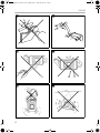
• To prevent damage when drilling, make sure there is sufficient space on the other
side for the drill head to come out (fig. 2, page 4).
• Deburr all drill holes and treat them with a rust-protection agent.
CAM44-IO-16s.book Seite 13 Mittwoch, 5. Oktober 2016 11:38 11

EN
Safety and installation instructions CAM44
14
• Always follow the safety instructions of the vehicle manufacturer.
Some work (e.g. on retention systems such as the AIRBAG etc.) may only be
performed by qualified specialists.
Observe the following instructions when working with electrical parts:
• When testing the voltage in electrical cables, only use a diode test lamp
(fig. 1 8, page 3) or a voltmeter (fig. 1 9, page 3).
Test lamps with an illuminant (fig. 1 12, page 3) consume voltages that are too
high and can damage the vehicle's electronic system.
• When making electrical connections, ensure that:
– They are not kinked or twisted
– They do not rub on edges
– They are not laid through sharp-edged ducts without protection (fig. 3,
page 4).
• Insulate all connections.
• Protect the cables from mechanical wear (for example rubbing against existing
cables) using cable binders or insulating tape.
The camera is watertight. However, the seals on the camera cannot withstand a high-
pressure cleaner (fig. 4, page 4). Therefore, you should observe the following
instructions when handling the camera:
• Do not open the camera, as this impairs the watertightness and the function of
the camera (fig. 5, page 4).
• Do not pull on the cables, as this impairs the watertightness and the function of
the camera (fig. 6, page 4).
• The camera is not suitable for use under water (fig. 7, page 4)!
CAM44-IO-16s.book Seite 14 Mittwoch, 5. Oktober 2016 11:38 11

EN
CAM44 Scope of delivery
15
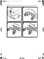
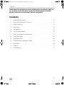
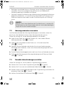
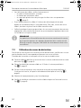
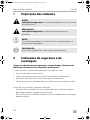
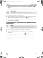
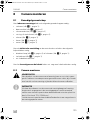
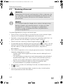
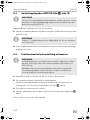
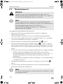
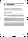
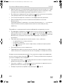
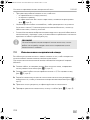
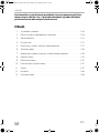
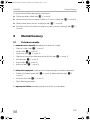
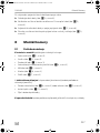
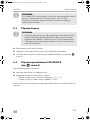
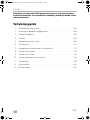
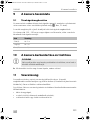
3Scope of delivery
4Accessories
Available as accessory (not included in scope of delivery):
5 Intended use
The CAM44 camera (item no. 9600000043) camera is designed primarily for use in
vehicles. It can be used in rear view video systems to observe the space behind the
vehicle from the driver's seat when manoeuvring or parking, for example.
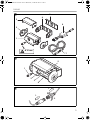
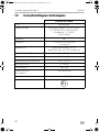
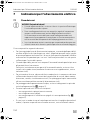
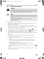
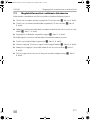
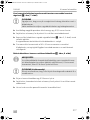
!
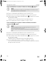
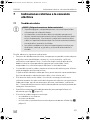
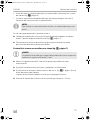
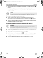
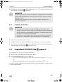
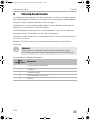
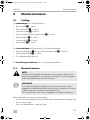
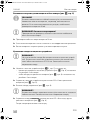
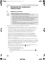
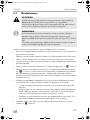
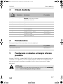
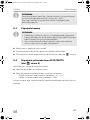
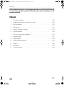
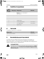
No. in
fig. 8,
page 5
Quantity Description Ref. no.
11Camera with motorised protective
cover
22Cover
3 1 Camera guard
4 1 Camera bracket
5 1 Insulation pad
6 1 CAM44 adapter box 9102200078
7 1 Extension cables 9102200030
– 1 Fastening material
Description Ref. no.
AMP100 switch box 9600000210
WARNING!
Since rear view systems are designed merely as an additional aid for
reversing, they do not relieve you of the duty to take proper care
when reversing.
CAM44-IO-16s.book Seite 15 Mittwoch, 5. Oktober 2016 11:38 11

EN
Technical description CAM44
16
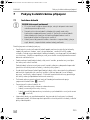
6 Technical description
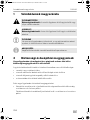
The colour camera with integrated microphone is encased in an aluminium housing
and transmits image and sound to a monitor via a cable. It has a close-up lens and a
long-range lens. The infrared LEDs improve night vision.
The long-distance lens shows the space behind the vehicle as if you were looking
through a rear window. You can switch it on when you are not reversing.
The close-up lens (reversing camera) is a wide-angle lens, which shows the area
directly behind the vehicle. It is activated when you engage reverse gear.
The camera produces three distance marks in reversing mode which are shown on a
connected colour monitor as coloured lines.
The CAM44 camera is equipped with a motorised cover to protect against dirt.
I
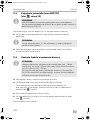
The camera consists of the following elements:
NOTE
The cameras were equipped with a reverse display at the factory. Any
monitor that is connected therefore needs a normal picture function.
No. in
fig. 9, page 5
Description
1 6-pin connection cable
2 Long-range lens
3 Infrared LEDs
4 Close-up lens (reversing camera)
5 Microphone
CAM44-IO-16s.book Seite 16 Mittwoch, 5. Oktober 2016 11:38 11

EN
CAM44 Notes on the electrical connections
17
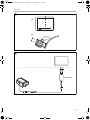
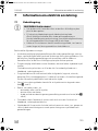
7 Notes on the electrical connections
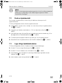
7.1 Laying cables
A
Please therefore observe the following instructions:
• As far as possible, use original openings or alternative openings for the
connecting cable duct, e.g. the paneling edges, ventilation grilles or blank
panels. If no openings are available, you must drill holes for the cables. Check
beforehand that there is sufficient room for the drill head to come out on the other
side.
• Wherever possible, lay cables inside the vehicle, as they are better protected
there than outside.
If you do need to lay a cable outside the vehicle, ensure that it is well fastened
(use additional cable ties, insulating tape etc.).
• To prevent damage to the cables, when laying them, ensure that they are far
enough away from hot or moving vehicle components (exhaust pipes, drive
shafts, light systems, fans, heater etc.). Use corrugated piping or other protective
materials to protect against mechanical wear.
• Screw on the plug connections of the connecting cables to protect against water
penetration (fig. 0, page 5).
• When laying the cables, make sure:
– They are not kinked or twisted
– They do not rub on edges
– They are not laid through sharp-edged ducts without protection (fig. 3,
page 4).
• Attach the cables securely in the vehicles to prevent tripping hazards. Use cable
binders, insulating tape or glue the cables in place.
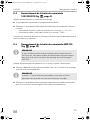
NOTICE! Risk of damage!
• To prevent damage, when drilling ensure that there is sufficient
space on the other side for the drill head to come out.
• Cables and connections which are not properly installed will cause
malfunctions or damage to components. Correct installation of
cables and connections is the basic prerequisite for lasting and
trouble-free operation of the retrofitted components.
• The cables may not be exposed for long periods to solvents such as
benzine, as the solvents can damage the cable.
CAM44-IO-16s.book Seite 17 Mittwoch, 5. Oktober 2016 11:38 11

EN
Notes on the electrical connections CAM44
18
• Protect every through-hole made in the bodywork against water penetration,
e.g. by using a cable with a sealant and by spraying the cable and the cable
sleeve with sealant.
I
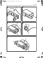
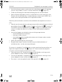
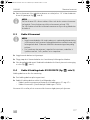
7.2 Using branch connectors
To prevent loose connections in the branch connectors, it is important to ensure that
the cable cross sections fit into the branch connectors.
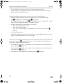
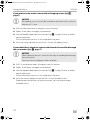
To use the branch connectors, proceed as follows:
➤ Insert the cable to be tapped in the front groove of the cable connector
(fig. a A, page 6).
➤ Insert the end of the new cable up to approx. 3/4 of the way into the rear groove
(fig. a B, page 6).
➤ Use a pair of combination pliers to close the connector by pressing the metal pin
in. This creates an electrical connection (fig. a C, page 6).
➤ Press down the safety cap until it snaps into place.
➤ Check that the connection is secure by gently tugging the cable (fig. a D,
page 6).
NOTE
Only start sealing through-holes when you have completed all
installation work on the camera and have laid the required cable lengths.
CAM44-IO-16s.book Seite 18 Mittwoch, 5. Oktober 2016 11:38 11

EN
CAM44 Notes on the electrical connections
19
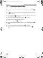
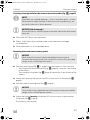
7.3 Creating clean soldering joints
Proceed as follows to solder a cable to the original cables:
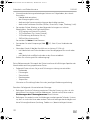
➤ Strip approx. 10 mm of insulation from the end of the original cable (fig. b A,
page 6).
➤ Strip approx. 15 mm of insulation from the end of the cable to be connected
(fig. b B, page 6).
➤ Wind the cable to be connected around the original cable and solder the two
cables together (fig. b C, page 6).
➤ Insulate the two cables with insulating tape (fig. b D, page 6).
Proceed as follows to solder two cables together:
➤ Strip the two cables (fig. c A, page 6).
➤ Place a shrink sleeve with a length of approx. 20 mm over the cable (fig. c B,
page 6).
➤ Twist the cables together and solder them (fig. c C, page 6).
➤ Place a shrink sleeve over the soldered point and heat it briefly (fig. c D,
page 6).
CAM44-IO-16s.book Seite 19 Mittwoch, 5. Oktober 2016 11:38 11

EN
Fitting the camera CAM44
20
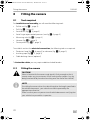
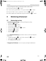
8 Fitting the camera
8.1 Tools required
For installation and assembly you will need the following tools:
• Drill bit set (fig. 1 1, page 3)
• Drill (fig. 1 2, page 3)
• Screwdriver (fig. 1 3, page 3)
• Set of ring or open-ended spanners (see fig. 1 4, page 3)
• Measuring ruler (fig. 1 5, page 3)
• Hammer (fig. 1 6, page 3)
• Centre punch (fig. 1 7, page 3)
To establish and test the electrical connection, the following tools are required:
• Diode test lamp (fig. 1 8, page 3) or voltmeter (fig. 1 9, page 3)
• Insulating tape (fig. 1 11, page 3)
• Cable bushing sleeves (optional)
To fasten the cables you may require additional cable binders.
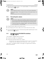
8.2 Fitting the camera
!
I
CAUTION!
Select a location for the camera and attach it firmly enough so that it
cannot under any circumstances fall off and injure bystanders (e.g. by
being knocked off by branches brushing over the roof of the vehicle).
NOTE
If installing the camera alters the vehicle height or the length specified in
the vehicle documents, your vehicle must be inspected by the
appropriate authorities.
Make sure that you are in possession of vehicle documents verifying that
your vehicle has passed this inspection.
CAM44-IO-16s.book Seite 20 Mittwoch, 5. Oktober 2016 11:38 11

EN
CAM44 Fitting the camera
21
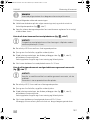
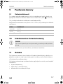
Observe the following installation instructions:
• Fix the camera at a height of at least two metres for an adequate view.
Make sure that you have a firm place from which to work when installing the
camera.
• Make sure that the installation location of the camera is sufficiently firm (e. g. to
prevent the camera from being knocked down by branches that may brush the
roof of the vehicle).
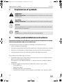
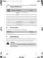
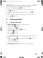
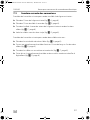
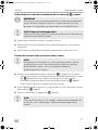
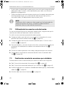
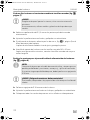
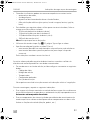
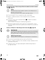
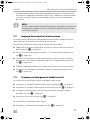
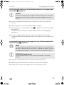
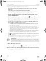
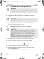
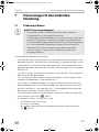
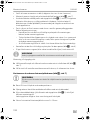
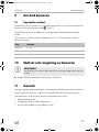
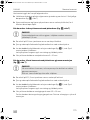
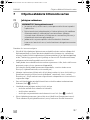
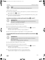
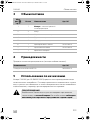
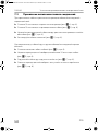
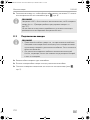
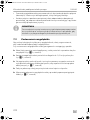
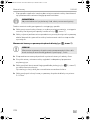
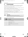
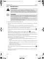
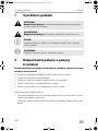
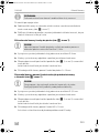
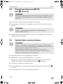
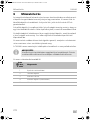
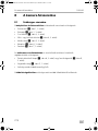
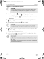
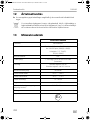
• Mount the camera horizontally and in the middle of the rear of the vehicle
(fig. d, page 7).
• Always use the supplied insulation pad (fig. 8 5, page 5). This prevents residual
current caused by a poor earth connections in the vehicle. Residual current can
cause lines of interference in the picture or buzzing in the loudspeakers or even
damage components.
• The most secure type of attachment is with screws fitted through the body.
Please observe the following instructions:
– There must be sufficient space behind the chosen installation location to be
able to carry out the mounting procedure.
– Suitable measures must be taken to prevent water penetrating through any
holes made (e.g. by using screws and sealant and/or spraying the outer
attachment parts with a sealant).
– The location on the body where you wish to attach the camera must be rigid
enough to allow the camera to be tightly fastened.
• Check beforehand that there is sufficient space on the other side for the drill head
to come out (fig. 2, page 4).
• If you are not sure about the location you have chosen, ask your vehicle manufac-
turer or dealer.
I
To perform the installation, proceed as follows:
➤ Hold the camera holder at the chosen location and mark at least two different
points for the drill holes (fig. e, page 7).
➤ Using a hammer and centre punch, gently pre-punch the previously marked
points to prevent the drill head from slipping off.
NOTE
We recommend greasing the threads of the screws to prevent
corrosion.
CAM44-IO-16s.book Seite 21 Mittwoch, 5. Oktober 2016 11:38 11

EN
Fitting the camera CAM44
22
If you want to screw on the camera with self-tapping screws (fig. f,
page 7)
A
➤ Drill 4 mm diameter holes at the points you just marked.
➤ Deburr all drill holes and apply rust-protection.
➤ Stick the double-sided adhesive insulation (fig. 8 5, page 5) to the assembly
side of the bracket.
The insulation plate serves as a seal and protects the paint.
➤ Screw the camera bracket on with the 5 x 20 mm self-tapping screws.
If you would like to attach the camera with threaded screws fitted through
the construction (fig. g, page 7)
A
➤ Drill 5.5 mm diameter holes at the points you just marked.
➤ Deburr all drill holes and apply rust-protection.
➤ Stick the double-sided adhesive insulation (fig. 8 5, page 5) to the assembly
side of the bracket.
The insulation plate serves as a seal and protects the paint.
➤ Screw the camera holder on with the M5 x 20 mm threaded screws.
Depending on the thickness of the construction, you may require longer
threaded screws.
NOTICE!
Self-tapping screws may only be fastened to steel metal with a minimum
thickness of 1.5 mm.
NOTICE!
When tightening the nuts, make sure that they cannot be pulled through
the construction.
You may have to use bigger washers or plates.
CAM44-IO-16s.book Seite 22 Mittwoch, 5. Oktober 2016 11:38 11

EN
CAM44 Fitting the camera
23
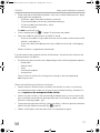
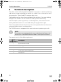
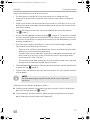
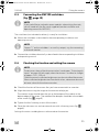
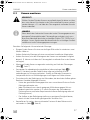
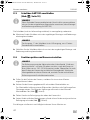
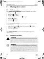
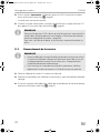
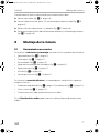
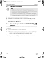
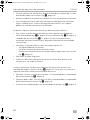
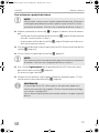
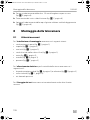
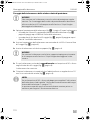
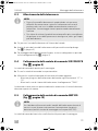
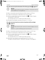
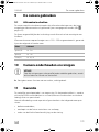
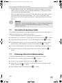
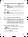
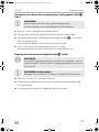
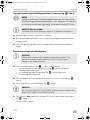
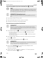
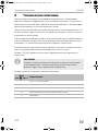
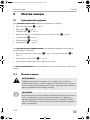
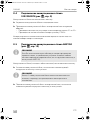
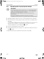
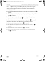
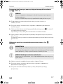
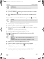
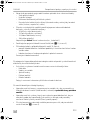
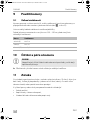
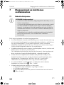
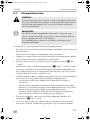
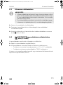
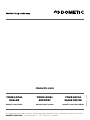
Creating a through-hole for the camera connection cable (fig. h, page 8)
I
A
➤ Drill a hole of Ø 16 mm near the camera.
➤ Deburr all drill holes that have been made in the sheet metal and apply
rust-protection.
➤ Place cable sleeves in all sharp-edged ducts.
Attaching the camera and camera guard
A
➤ Push the camera guard (fig. 8 3, page 5) over the camera in such a way that:
– The fixing hole of the camera guard (fig. i, page 8) is over the 3 mm thread
of the camera.
– The two other fixing holes (fig. i, page 8) are over the 3 mm threads of the
camera.
➤ Secure the camera guard with the two M3 x 6 mm screws in the hole (fig. i,
page 8).
➤ Push the camera into the bracket (fig. j, page 8).
A
➤ Secure the camera loosely with the four M3 x 8 mm screws in the two other
fixing holes (fig. j, page 8).
The camera is now centred.
NOTE
If possible, use available openings – such as ventilation grilles – to feed
the connection cables through. If there are no existing openings, you
must drill a hole with a 16 mm diameter.
NOTICE! Risk of damage!
Ensure that there is sufficient space on the other side for the drill head to
come out
NOTICE!
Never mount the camera without the additional camera guard.
To mount the camera guard, only use the M3 x 6 mm screws provided.
Longer screws will damage the camera.
NOTICE!
Only use the screws supplied to mount the camera in the camera holder.
Longer screws will damage the camera.
CAM44-IO-16s.book Seite 23 Mittwoch, 5. Oktober 2016 11:38 11
Page is loading ...
Page is loading ...
Page is loading ...
Page is loading ...
Page is loading ...
Page is loading ...
Page is loading ...
Page is loading ...
Page is loading ...
Page is loading ...
Page is loading ...
Page is loading ...
Page is loading ...
Page is loading ...
Page is loading ...
Page is loading ...
Page is loading ...
Page is loading ...
Page is loading ...
Page is loading ...
Page is loading ...
Page is loading ...
Page is loading ...
Page is loading ...
Page is loading ...
Page is loading ...
Page is loading ...
Page is loading ...
Page is loading ...
Page is loading ...
Page is loading ...
Page is loading ...
Page is loading ...
Page is loading ...
Page is loading ...
Page is loading ...
Page is loading ...
Page is loading ...
Page is loading ...
Page is loading ...
Page is loading ...
Page is loading ...
Page is loading ...
Page is loading ...
Page is loading ...
Page is loading ...
Page is loading ...
Page is loading ...
Page is loading ...
Page is loading ...
Page is loading ...
Page is loading ...
Page is loading ...
Page is loading ...
Page is loading ...
Page is loading ...
Page is loading ...
Page is loading ...
Page is loading ...
Page is loading ...
Page is loading ...
Page is loading ...
Page is loading ...
Page is loading ...
Page is loading ...
Page is loading ...
Page is loading ...
Page is loading ...
Page is loading ...
Page is loading ...
Page is loading ...
Page is loading ...
Page is loading ...
Page is loading ...
Page is loading ...
Page is loading ...
Page is loading ...
Page is loading ...
Page is loading ...
Page is loading ...
Page is loading ...
Page is loading ...
Page is loading ...
Page is loading ...
Page is loading ...
Page is loading ...
Page is loading ...
Page is loading ...
Page is loading ...
Page is loading ...
Page is loading ...
Page is loading ...
Page is loading ...
Page is loading ...
Page is loading ...
Page is loading ...
Page is loading ...
Page is loading ...
Page is loading ...
Page is loading ...
Page is loading ...
Page is loading ...
Page is loading ...
Page is loading ...
Page is loading ...
Page is loading ...
Page is loading ...
Page is loading ...
Page is loading ...
Page is loading ...
Page is loading ...
Page is loading ...
Page is loading ...
Page is loading ...
Page is loading ...
Page is loading ...
Page is loading ...
Page is loading ...
Page is loading ...
Page is loading ...
Page is loading ...
Page is loading ...
Page is loading ...
Page is loading ...
Page is loading ...
Page is loading ...
Page is loading ...
Page is loading ...
Page is loading ...
Page is loading ...
Page is loading ...
Page is loading ...
Page is loading ...
Page is loading ...
Page is loading ...
Page is loading ...
Page is loading ...
Page is loading ...
Page is loading ...
Page is loading ...
Page is loading ...
Page is loading ...
Page is loading ...
Page is loading ...
Page is loading ...
Page is loading ...
Page is loading ...
Page is loading ...
Page is loading ...
Page is loading ...
Page is loading ...
Page is loading ...
Page is loading ...
Page is loading ...
Page is loading ...
Page is loading ...
Page is loading ...
Page is loading ...
Page is loading ...
Page is loading ...
Page is loading ...
Page is loading ...
Page is loading ...
Page is loading ...
Page is loading ...
Page is loading ...
Page is loading ...
Page is loading ...
Page is loading ...
Page is loading ...
Page is loading ...
Page is loading ...
Page is loading ...
Page is loading ...
Page is loading ...
Page is loading ...
Page is loading ...
Page is loading ...
Page is loading ...
Page is loading ...
Page is loading ...
Page is loading ...
Page is loading ...
Page is loading ...
Page is loading ...
Page is loading ...
Page is loading ...
Page is loading ...
Page is loading ...
Page is loading ...
Page is loading ...
Page is loading ...
Page is loading ...
Page is loading ...
Page is loading ...
Page is loading ...
Page is loading ...
Page is loading ...
Page is loading ...
Page is loading ...
Page is loading ...
Page is loading ...
Page is loading ...
Page is loading ...
Page is loading ...
Page is loading ...
Page is loading ...
Page is loading ...
Page is loading ...
Page is loading ...
Page is loading ...
Page is loading ...
Page is loading ...
Page is loading ...
Page is loading ...
Page is loading ...
Page is loading ...
Page is loading ...
Page is loading ...
Page is loading ...
Page is loading ...
Page is loading ...
Page is loading ...
Page is loading ...
Page is loading ...
Page is loading ...
Page is loading ...
Page is loading ...
Page is loading ...
Page is loading ...
Page is loading ...
Page is loading ...
Page is loading ...
Page is loading ...
Page is loading ...
Page is loading ...
Page is loading ...
Page is loading ...
Page is loading ...
Page is loading ...
Page is loading ...
Page is loading ...
Page is loading ...
Page is loading ...
Page is loading ...
Page is loading ...
Page is loading ...
Page is loading ...
Page is loading ...
Page is loading ...
Page is loading ...
Page is loading ...
Page is loading ...
Page is loading ...
Page is loading ...
Page is loading ...
Page is loading ...
Page is loading ...
Page is loading ...
Page is loading ...
Page is loading ...
-
 1
1
-
 2
2
-
 3
3
-
 4
4
-
 5
5
-
 6
6
-
 7
7
-
 8
8
-
 9
9
-
 10
10
-
 11
11
-
 12
12
-
 13
13
-
 14
14
-
 15
15
-
 16
16
-
 17
17
-
 18
18
-
 19
19
-
 20
20
-
 21
21
-
 22
22
-
 23
23
-
 24
24
-
 25
25
-
 26
26
-
 27
27
-
 28
28
-
 29
29
-
 30
30
-
 31
31
-
 32
32
-
 33
33
-
 34
34
-
 35
35
-
 36
36
-
 37
37
-
 38
38
-
 39
39
-
 40
40
-
 41
41
-
 42
42
-
 43
43
-
 44
44
-
 45
45
-
 46
46
-
 47
47
-
 48
48
-
 49
49
-
 50
50
-
 51
51
-
 52
52
-
 53
53
-
 54
54
-
 55
55
-
 56
56
-
 57
57
-
 58
58
-
 59
59
-
 60
60
-
 61
61
-
 62
62
-
 63
63
-
 64
64
-
 65
65
-
 66
66
-
 67
67
-
 68
68
-
 69
69
-
 70
70
-
 71
71
-
 72
72
-
 73
73
-
 74
74
-
 75
75
-
 76
76
-
 77
77
-
 78
78
-
 79
79
-
 80
80
-
 81
81
-
 82
82
-
 83
83
-
 84
84
-
 85
85
-
 86
86
-
 87
87
-
 88
88
-
 89
89
-
 90
90
-
 91
91
-
 92
92
-
 93
93
-
 94
94
-
 95
95
-
 96
96
-
 97
97
-
 98
98
-
 99
99
-
 100
100
-
 101
101
-
 102
102
-
 103
103
-
 104
104
-
 105
105
-
 106
106
-
 107
107
-
 108
108
-
 109
109
-
 110
110
-
 111
111
-
 112
112
-
 113
113
-
 114
114
-
 115
115
-
 116
116
-
 117
117
-
 118
118
-
 119
119
-
 120
120
-
 121
121
-
 122
122
-
 123
123
-
 124
124
-
 125
125
-
 126
126
-
 127
127
-
 128
128
-
 129
129
-
 130
130
-
 131
131
-
 132
132
-
 133
133
-
 134
134
-
 135
135
-
 136
136
-
 137
137
-
 138
138
-
 139
139
-
 140
140
-
 141
141
-
 142
142
-
 143
143
-
 144
144
-
 145
145
-
 146
146
-
 147
147
-
 148
148
-
 149
149
-
 150
150
-
 151
151
-
 152
152
-
 153
153
-
 154
154
-
 155
155
-
 156
156
-
 157
157
-
 158
158
-
 159
159
-
 160
160
-
 161
161
-
 162
162
-
 163
163
-
 164
164
-
 165
165
-
 166
166
-
 167
167
-
 168
168
-
 169
169
-
 170
170
-
 171
171
-
 172
172
-
 173
173
-
 174
174
-
 175
175
-
 176
176
-
 177
177
-
 178
178
-
 179
179
-
 180
180
-
 181
181
-
 182
182
-
 183
183
-
 184
184
-
 185
185
-
 186
186
-
 187
187
-
 188
188
-
 189
189
-
 190
190
-
 191
191
-
 192
192
-
 193
193
-
 194
194
-
 195
195
-
 196
196
-
 197
197
-
 198
198
-
 199
199
-
 200
200
-
 201
201
-
 202
202
-
 203
203
-
 204
204
-
 205
205
-
 206
206
-
 207
207
-
 208
208
-
 209
209
-
 210
210
-
 211
211
-
 212
212
-
 213
213
-
 214
214
-
 215
215
-
 216
216
-
 217
217
-
 218
218
-
 219
219
-
 220
220
-
 221
221
-
 222
222
-
 223
223
-
 224
224
-
 225
225
-
 226
226
-
 227
227
-
 228
228
-
 229
229
-
 230
230
-
 231
231
-
 232
232
-
 233
233
-
 234
234
-
 235
235
-
 236
236
-
 237
237
-
 238
238
-
 239
239
-
 240
240
-
 241
241
-
 242
242
-
 243
243
-
 244
244
-
 245
245
-
 246
246
-
 247
247
-
 248
248
-
 249
249
-
 250
250
-
 251
251
-
 252
252
-
 253
253
-
 254
254
-
 255
255
-
 256
256
-
 257
257
-
 258
258
-
 259
259
-
 260
260
-
 261
261
-
 262
262
-
 263
263
-
 264
264
-
 265
265
-
 266
266
-
 267
267
-
 268
268
-
 269
269
-
 270
270
-
 271
271
-
 272
272
-
 273
273
-
 274
274
-
 275
275
-
 276
276
-
 277
277
-
 278
278
-
 279
279
-
 280
280
-
 281
281
-
 282
282
-
 283
283
-
 284
284


Dometic PerfectView CAM44 Operating instructions
- Type
- Operating instructions
- This manual is also suitable for
Ask a question and I''ll find the answer in the document
Finding information in a document is now easier with AI
in other languages
- italiano: Dometic PerfectView CAM44 Istruzioni per l'uso
- français: Dometic PerfectView CAM44 Mode d'emploi
- español: Dometic PerfectView CAM44 Instrucciones de operación
- Deutsch: Dometic PerfectView CAM44 Bedienungsanleitung
- русский: Dometic PerfectView CAM44 Инструкция по эксплуатации
- Nederlands: Dometic PerfectView CAM44 Handleiding
- português: Dometic PerfectView CAM44 Instruções de operação
- slovenčina: Dometic PerfectView CAM44 Návod na používanie
- dansk: Dometic PerfectView CAM44 Betjeningsvejledning
- polski: Dometic PerfectView CAM44 Instrukcja obsługi
- čeština: Dometic PerfectView CAM44 Operativní instrukce
- svenska: Dometic PerfectView CAM44 Bruksanvisningar
- suomi: Dometic PerfectView CAM44 Käyttö ohjeet
Related papers
-
Dometic PerfectView SPK150, SPK160, SPK170, SPK180-V Installation guide
-
-
-
Waeco Waeco mobitronic RV-700 Operating instructions
-
-
-
Waeco PerfectView CAM50 Owner's manual
-
-
-
Other documents
-
Clarion CC-1030E Owner's manual
-
-
-
-
-
Teleco Retrocamera TRC 14CCD User manual
-
AudioSource 2 Channel Amplifier With Auto Switching Dual Inputs User manual
-
-
-
Calex Outdoor LED Smart Outdoor Frameless Floodlight User manual