Barco Graphics 808s R9000904 User manual
- Category
- Projectors
- Type
- User manual

GRAPHICS
808s
R9000901 - R9000908
R9000902 - R9000907
INSTALLATION MANUAL


GRAPHICS
808s
BARCO PROJECTION SYSTEMS
Date :
241197
Art. No. :
R5975996
R9000901 - R9000908
R9000902 - R9000907
INSTALLATION MANUAL
Revision :
04

Due to constant research, the information in this manual is subject to change without notice.
Produced by BARCO NV, November 1997.
All rights reserved.
Trademarks are the rights of their respective owners.
Printed in Belgium
BARCO nv/Projection Systems
Noordlaan 5
B-8520 Kuurne
Belgium
Printed in Belgium

Table of contents
i-1
5975996 BARCOGRAPHICS 808s 241197
Contents
CHAPTER 1 SAFETY INSTRUCTIONS
On safety .................................................................................................................................................... 1-1
On installation ............................................................................................................................................ 1-2
On servicing ................................................................................................................................................ 1-2
On cleaning ................................................................................................................................................ 1-2
On repacking .............................................................................................................................................. 1-2
On illumination............................................................................................................................................ 1-2
CHAPTER 2 UNPACKING AND PROJECTOR DIMENSIONS
Unpacking .................................................................................................................................................. 2-1
Projector dimensions .................................................................................................................................. 2-2
CHAPTER 3 INSTALLATION GUIDELINES
Environment ................................................................................................................................................ 3-1
What about ambient light ? ........................................................................................................................ 3-1
Which screen type? ................................................................................................................................... 3-1
What image size? How big should the image be? ..................................................................................... 3-1
Where to install the projector ? .................................................................................................................. 3-2
Mounting Configuration ............................................................................................................................... 3-2
CHAPTER 4 INSTALLATION SETUP
Access to Controls ..................................................................................................................................... 4-1
Opening the top cover ................................................................................................................................................................... 4-1
Removing the top cover ................................................................................................................................................................ 4-1
Reinstalling the top cover .............................................................................................................................................................. 4-1
Scan Adaptation ......................................................................................................................................... 4-2
Getting access to the scan switches .......................................................................................................................................... 4-2
Horizontal scan switches ............................................................................................................................................................. 4-2
Vertical scan switch ..................................................................................................................................................................... 4-2
CHAPTER 5 PROJECTOR SETUP
Setting the projector address ..................................................................................................................... 5-1
Powerup mode............................................................................................................................................ 5-2
Operational mode ........................................................................................................................................................................... 5-2
Standby mode ................................................................................................................................................................................ 5-2
Baud Rate for communication with a computer .......................................................................................... 5-3
Password mode .......................................................................................................................................... 5-3

Table of contents
i-2 5975996 BARCOGRAPHICS 808s 241197
CHAPTER 6 AC POWER CONNECTION
AC Power cord connection ......................................................................................................................... 6-1
Preparing your power cord .......................................................................................................................... 6-1
Mains lead with CEE7 plug ............................................................................................................................................................ 6-1
Power cord with an ANSI 73.11 plug ........................................................................................................................................... 6-1
AC Power check......................................................................................................................................... 6-2
AC Input power voltage adaptation.............................................................................................................. 6-2
Switching on the projector .......................................................................................................................... 6-3
Starting up with a full white image .............................................................................................................. 6-3
Starting up with "warm up period" ................................................................................................................................................ 6-3
Starting up without "warm up period" .......................................................................................................................................... 6-3
CHAPTER 7 SOURCE CONNECTIONS
Signal input connection .............................................................................................................................. 7-1
Connecting a Composite Video source to Port 1 ........................................................................................ 7-1
Connecting a S-Video (or Composite Video) source to Port 2 .................................................................... 7-2
Connecting a RGB Analog source to Port 3 ............................................................................................... 7-2
Connecting a RGB Analog source to Port 4/5 ............................................................................................ 7-3
Connecting a Component Video source to Port 4/5 .................................................................................... 7-3
Connecting a RGB Analog source with Tri-level sync to Port 4/5 (option) .................................................. 7-4
Connecting a Component Video source with Tri-level sync to Port 4/5 (option) .......................................... 7-4
Peripheral equipment .................................................................................................................................. 7-4
Connecting a RCVDS 05 source selector to the BARCOGRAPHICS 808s .................................................................................. 7-4
Connecting a VS05 source selector to the BARCOGRAPHICS 808s .......................................................................................... 7-4
Connecting an IR Remote Receiver 800 to the BARCOGRAPHICS 808s ..................................................................................... 7-4
CHAPTER 8 INSTALLATION ADJUSTMENT MODE
Access to Installation Adjustment Mode .................................................................................................... 8-1
Overview flowchart of the Installation Adjustment Mode .............................................................................. 8-1
Projector Distance ...................................................................................................................................... 8-2
Optical Lens Focusing................................................................................................................................ 8-2
Raster Centering ......................................................................................................................................... 8-3
CRT Projection Angle Adjustment .............................................................................................................. 8-4
Scheimpflug Adjustment ............................................................................................................................. 8-6
CHAPTER 9 MESSAGES, WARNINGS AND FAILURE CODES
APPENDIX A. BARCO CEILING MOUNT SUPPORT
APPENDIX B. G2 ADJUSTMENT
APPENDIX C. GAMMA CORRECTIONS

Safety instructions
1-1
5975996 BARCOGRAPHICS 808s 241197
1
SAFETY INSTRUCTIONS
Projectors are built in accordance with the requirements of the
international safety standards IEC950, UL 1950 and CSA C22.2 No.
950, which are the safety standards of information technology equip-
ment including electrical business equipment.
These safety standards impose important requirements on the use of
safety critical components, materials and isolation, in order to protect
the user or operator against the risk of electric shock and energy
hazard, and having access to live parts.
Safety standards also impose to the internal and external tempera-
ture variations, radiation levels, mechanical stability and strength,
enclosure construction and protection against risk of fire.
Simulated single fault condition testing ensures the safety of the
equipment to the user even when the equipment's normal operation
fails.
Installation instructions
Before operating your projector please read this manual thoroughly,
and retain it for future reference.
Installation and preliminary adjustments should be performed by
qualified BARCO personnel or authorized BARCO service dealers.
OWNERS RECORD
The article number (ART. NR.) and serial number (SER. NR) are
located at the rear of the projector. Copy these numbers in the spaces
provided below. Refer to them whenever you call upon your BARCO
dealer regarding this product.
Article number :
Serial number :
Dealer :
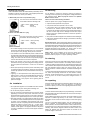
The lightning flash with an arrowhead within a
triangle is intended to tell the user that parts
inside this product risk electrical shock to
persons.
The exclamation point within a triangle is
intended to tell the user that important operat-
ing and/or servicing instructions are included
in the technical documentation for this
equipment.
Warning :
To prevent fire or electrical shock hazard,
do not expose this projector to rain or moisture
Federal Communication Commission (FCC statement)
This equipment has been tested and found to comply with the limits
for a class B digital device, pursuant to Part 15 of the FCC Rules.
These limits are designed to provide reasonable protection against
harmful interference when the equipment is operated in a commercial
environment. This equipment generates, uses, and can radiate radio
frequency energy and, if not installed and used in accordance with the
instruction manual, may cause harmful interference to radio commu-
nications. Operation of this equipment in a residential area is likely to
cause harmful interference in which case the user will be required to
correct the interference at his own expense.
Instructions to the user :
If this equipment does cause interference to radio or television
reception, the user may try to correct the interference by one or more
of the following measures :
Re-orientate the receiving antenna for the radio or television.
Relocate the equipment with respect to the receiver.
Plug the equipment into a different outlet so that the equipment and
receiver are on different branch circuits.
Fasten cable connectors to the equipment with mounting screws.
Note :
The use of shielded cables is required to comply within the limits of
Part 15 of FCC rules and EN55022.
General safety instructions :
All the safety and operating instructions should be read before
using this unit.
The operating instruction manual should be retained for future
reference.
All warnings on the projector and in the documentation manuals
should be adhered to.
All instructions for operating and use of this equipment must be
followed precisely.
On safety
This product should be operated from an AC power source.
Operating AC power voltage of the projector when leaving the
factory:
BARCOGRAPHICS 808s
Art. No.: R9000901 (230 VAC) Art. No.: R9000908 (120 VAC)
BARCOGRAPHICS 808s with built-in Iris
2
Art. No.: R9000902 (230 VAC) Art. No.: R9000907 (120 VAC)
Consult the appropriate section of this manual to switch over from
230 Vac to 120 Vac or from 120 Vac to 230 Vac.
If you are not sure of the type of AC power available, consult your
dealer or local power company.
This product is equipped with a 3-wire grounding plug, a plug
having a third (grounding) pin. This plug will only fit into a grounding-
type power outlet. This is a safety feature. If you are unable to insert
the plug into the outlet, contact your electrician to replace your
obsolete outlet. Do not defeat the purpose of the grounding-type
plug.

Safety instructions
1-2 5975996 BARCOGRAPHICS 808s 241197
On servicing
Do not attempt to service this projector yourself, as opening or
removing covers may expose you to dangerous voltage potential and
risk of electric shock! Refer all projector service to a qualified
BARCO service center.
Call for service in the following conditions :
When the power cord or plug is damaged or frayed.
If liquid has been spilled into the projector.
If the product has been exposed to rain or water.
If the product does not operate normally when the operating
instructions are followed. Adjust only those controls that are
covered by the operating instructions since improper adjustment of
the other controls may result in damage and will often require
extensive work by a qualified technician to restore the product to
normal operation.
If the product has been dropped or the cabinet has been damaged.
If the product exhibits a distinct change in performance, indicating
a need for service.
Replacement parts - When replacement parts are required, be sure
the service technician has used original BARCO replacement parts or
authorized replacement parts which have the same characteristics as
the BARCO original part. Unauthorized substitutions may result in
degraded performance and reliability, fire, electric shock or other
hazards. Unauthorized substitutions may void warranty.
Safety check - Upon completion of any service or repairs to this
projector, ask the service technician to perform safety checks to
determine that the projector is in proper operating condition.
On cleaning
Unplug this product from the wall outlet before cleaning. Do not use
liquid cleaners or aerosol cleaners. Use a damp cloth for cleaning.
To keep the cabinet looking brand-new, periodically clean it with a soft
cloth. Stubborn stains may be removed with a cloth lightly dampened
with mild detergent solution. Never use strong solvents, such as
thinner or benzine, or abrasive cleaners, since these will damage the
cabinet.
To ensure the highest optical performance and resolution, the projec-
tion lenses are specially treated with an anti-reflective coating,
therefore : avoid touching the lens. To remove dust on the lens, use
a soft dry cloth. Do not use a damp cloth, detergent solution, or
thinner.
On repacking
Keep the original shipping carton and packing material; they will come
in handy if you ever have to ship your projector. For maximum
protection, repack your set as it was originally packed at the factory.
On illumination
In order to obtain the best quality for the projected image, it is essential
that the ambient light which is allowed to fall on the screen be kept to
an absolute minimum.
When installing the projector and screen, care must be taken to avoid
exposure to ambient light directly on the screen. Avoid adverse
illumination on the screen from direct sunlight or fluorescent lighting
fixtures.
The use of controlled ambient lighting, such as incandescent spot
light or a dimmer, is recommended for proper room illumination.
Where possible, care should also be taken to ensure that the floors
and walls of the room in which the projector is to be installed are non-
reflecting, dark surfaces. Brighter surfaces will tend to reflect and
diffuse the ambient light and hence reduce the contrast of the
projected image on the screen.
WARNING FOR THE USERS:
THIS EQUIPMENT MUST BE GROUNDED (EARTHED) via the
supplied 3 conductor AC power cable. (If the supplied power cable
is not the correct one, consult your dealer.)
A. Mains lead (AC Power cord) with CEE 7 plug
The colors of the mains lead are colored
in accordance with the following code:
Yellow + Green : Earth (Ground)
Blue : Neutral
Brown : Line (Live)
B. Power cord with ANSI 73.11 plug
The wires of the power cord are colored in
accordance with the following code.
Yellow + Green : Earth (Ground)
White : Neutral
Black : Line (live)
Do not allow anything to rest on the power cord. Do not locate
this product where people will walk on the cord. To disconnect
the cord, pull it out by the plug. Never pull the cord itself.
If an extension cord is used with this product, make sure that
the total of the ampere ratings on the products plugged into the
extension cord does not exceed the extension cord ampere
rating. Also make sure that the total of all products plugged
into the wall outlet does not exceed 15 amperes.
Never push objects of any kind into this product through
cabinet slots as they may touch dangerous voltage points or
short out parts that could result in a risk of fire or electrical
shock.
Never spill liquid of any kind on the product. Should any liquid
or solid object fall into the cabinet, unplug the set and have it
checked by qualified service personnel before resuming op-
erations.
Lightning - For extra protection for this video product during a
lightning storm, or when it is left unattended and unused for a
long period of time, unplug it from the wall outlet. This will
prevent damage to the projector due to lightning and AC
power-line surges.
On installation
Do not place this projector on an unstable cart, stand, or table.
The projector may fall, causing serious damage to it.
Do not use this projector near water.
Use only the power cord supplied with your projector. While
appearing to be similar, other power cords have not been
safety tested at the factory and may not be used to power the
projector. For a replacement power cord, contact your dealer.
Slots and openings in the cabinet and the sides are provided
for ventilation; to ensure reliable operation of the projector and
to protect it from overheating, these openings must not be
blocked or covered. The openings should never be blocked by
placing the product on a bed, sofa, rug, or other similar
surface. This product should never be placed near or over a
radiator or heat register. This projector should not be placed
in a built-in installation or enclosure unless proper ventilation
is provided.

Unpacking and dimensions
2-1
5975996 BARCOGRAPHICS 808s 241197
2
UNPACKING AND PROJECTOR DIMENSIONS
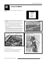
Unpacking
Contents of the shipping carton :
1 BARCOGRAPHICS 808s projector
1 Remote Control Unit plus 1 battery 9V
1 Power cord with outlet plug type CEE7 or ANSI 73.11
1 Owner's Manual
1 Installation Manual
To open the banding around the carton, pull out the clip as shown
below :
Take the projector out of its shipping carton and place it on a table.
Save the original shipping carton and packing material, which will
come in handy if you ever have to ship your projector. For maximum
protection, repack your projector as it was originally packed at the
factory.

Unpacking and dimensions
2-2 5975996 BARCOGRAPHICS 808s 241197
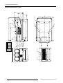
Projector dimensions (in mm)
1040
A
596
169.5
ROTATION COVER
*SERVICE*
GRAVITY POINT
CRT POINT
362
B
286
226
170
84
27
45.5
136
728
960
MAX 500
FIXATION POINT
*4 X M8*
MAX 1076
AIRFLOW
AIRFLOW
AIRFLOW
AIRFLOW
703148
MAX 428
590
FRONT IR RECEIVER
456
558
576
POWER SUPPLY
BACK IR RECEIVER
510
590
APPROXIMATE WEIGHT WITH HD8 LENS - 67 KG
CRT
CRT POINT
A
806 209
R7627612
R7627615
R7627616
R7626572
R7626575
R7626576
816 211
B

Installation guidelines
3-1
5975996 BARCOGRAPHICS 808s 241197
3
INSTALLATION GUIDELINES
Installation guidelines
Careful consideration of things such as image size, ambient light
level, projector placement and type of screen to use are critical
to optimize the use of the projection system.
Environment
Do not install the projection system in a site near heat sources such
as radiators or air ducts, or in a place subject to direct sunlight,
excessive dust or humidity. Be aware that room heat rises to the
ceiling; Make sure the temperature near the installation site is not
excessive.
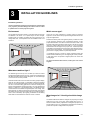
What about ambient light ?
The ambient light level of any room is made up of direct or indirect
sunlight and the light fixtures in the room. The amount of ambient light
will determine how bright the image will appear. So, avoid direct light
on the screen as much as possible.
Windows that face the screen should be covered by opaque drapery
while the set is being viewed. It is desirable to install the projecting
system in a room whose walls and floor are of non-reflecting material.
The use of recessed ceiling lights and a method of dimming those
lights to an acceptable level is also important. Too much ambient light
results in a wash out of the projected image. This appears as less
contrast between the darkest and lightest parts of the image. With
bigger screens, the wash out becomes more important. As a general
rule, darken the room to the point where there is just sufficient light to
read or write comfortably. Spot lighting is desirable for illuminating
small areas so that interference with the screen is minimal.
What image size? How big should the image
be?
The BARCOGRAPHICS 808s is designed for projecting an image
width from 1.4m (4.6') to 6m (20') with an aspect ratio of 4 to 3. It
leaves the BARCO factory, adjusted as a ceiling/front projector for a
screen width of 2.4m (7.8'). Changing the image size from the factory
preset size requires a realignment of the projector.
Which screen type?
There are two major categories of screens used for projection
equipment. Those used for front projected images and those for rear
projection applications.
Screens are rated by how much light they reflect (or transmit in case
of rear projection systems) given a determined amount of light
projected toward them. The GAIN of a screen is the term used. Front
and rear screens are both rated in terms of gain. The gain of screens
range from a white matte screen with a gain of 1 (x1) to a brushed
aluminized screen with a gain of 10 (x10) or more. Another important
consideration is the degree the screen's gain varies with the horizon-
tal and vertical viewing angle. The choice between higher and lower
gain screens is largely a matter of personal preference.
In considering the type of screen to choose, determine where the
viewers will be located and go for the highest gain screen possible.
A high gain screen will provide a brighter picture but reduce the
viewing angle.
For more information about screens, contact your local screen
supplier.

Installation guidelines
3-2 5975996 BARCOGRAPHICS 808s 241197
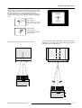
Where to install the projector ?
To indicate a correct installation position it is necessary to know :
The distance from projector to ceiling in case of Ceiling mounted
or the distance from projector to floor in case of Table mounted;
The distance from projector to screen.
To find the correct position for the BARCOGRAPHICS 808s, equipped
with HD8 lenses, use the following formulas:
Install the projector water levelled in both directions
Install the projector perpendicular to the screen
PD[inch] = 1.269 x SW[inch] + 13.54
A[inch] = 0.12 x SW[inch] - 11.11
In metric :
In inch :
PD[m] = 1.269 x SW[m] + 0.344
A[cm] = 12 x SW[m] - 28.2
Abbreviations used in the calculations and the drawings :
B = Distance between ceiling and top of the screen (Ceiling mounted)
or distance between floor and bottom of the screen (Table
mounted).
A = Correction Value, extra value to be added to B to obtain the
correct installation position (In some cases the A value can be
negative).
CD = Total distance between projector and ceiling (Ceiling mounted)
or total distance between projector and floor (Table mounted).
CD = A + B.
Ceiling Mounted : when the result is negative, enlarge the
distance between ceiling and top of the screen, mount screen
lower, until CD becomes zero or positive.
Table Mounted : when the result is negative, enlarge the
distance between floor and bottom of the screen, mount
screen higher, until CD becomes zero or positive.
SW = Screen width.
PD = Perpendicular distance between screen and projector's mount.
To obtain the right values, you can make use of the new option
included in the Installation Adjustment Mode to let the projector
calculate the parameters automatically. Please refer to Chapter 8 for
details.
11.5 cm
green phospho
Used phosphor width on the CRT faceplate (e.g. green CRT)
Mounting Configuration
Ceiling Mount
To install the BARCOGRAPHICS 808s in the Ceiling configuration,
use BARCO'S Ceiling Mount Kit (CM100) - Order Number R9827341.
Installation instructions are included with this kit.
Table Mount
BARCO offers a heavy-duty projection table with adjustable height
which allows the projector to be correctly positioned perfectly to the
installation requirements. Order Number - R9827740.
(4.5 inch)
Green phosphor

Installation setup
4-1
5975996 BARCOGRAPHICS 808s 241197
4
INSTALLATION SETUP
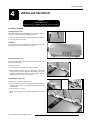
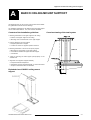
Removing the top cover
During some installations, it will be convenient to remove the top cover
from the projector totally.
Proceed as follows :
Pivot the top cover backwards 90° (fully extended);
Push carefully the top cover to the left side (viewing from the rear
of the projector) until the hinges are disengaged. This can be
facilitated by pressing downwards on the spring tabs next to the
hinges. Slide the top cover off the projector.
Reinstalling the top cover
To reinstall the top cover on the projector :
Place the top cover in front of the hinges (as shown in the picture)
and push in the direction of the black arrow until the cover locks
into the hinges;
Pivot the top cover to close;
Secure the locking screw by turning it clockwise with a screw-
driver.
WARNING :
Risk of electric shock !
Installation only by BARCO authorized service personnel !
Access to Controls
Opening the top cover
During the projector setup and installation it is necessary to open the
top cover. Follow the procedure described below :
Turn the locking screw with a screwdriver counter clockwise;
Lift up and pivot the top cover.
WARNING :
The projector's top cover is not supported with locking hinge. Open
with care and support the cover with your hand.

Installation setup
4-2 5975996 BARCOGRAPHICS 808s 241197
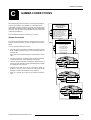
Scan Adaptation
The scan switches must be placed in the correct position which corresponds to the desired scanning configuration.
To change the scanning, it is necessary to remove the projector top cover and to open the protection plate.
For opening the projector's top cover, see 'Access to controls'.
WARNING !
TURN OFF PROJECTOR AND UNPLUG THE POWER
CORD BEFORE CHANGING THE SCAN DIRECTION.
- Repeat this action on both sides of the module and extract the
module out of the main frame.
Side view
Top view
Top view
Side view
Push
Three switches are used, one for each CRT. When changing the
horizontal scan, insure that all three switches are set in the same
position. See positions of the switches (diagram on next page) for
the corresponding projector configuration.
To set the scan switches :
Remove the horizontal deflection module (the second module
viewing from the rear of the projector).
To remove the horizontal deflection module :
- Press the module lock and lift up the module handle;
Horizontal deflection module
Toggle the 3 horizontal scan inversion switches (located just
underneath the horizontal amplitude module) to the correct
positions (see p.4-3).
Reinstall the horizontal deflection module.
Open the top cover and remove it from
the projector (see p.4-1);
Loosen the 3 retaining screws on each
side of the projector;
Open the protection plate and pivot it
forward (toward lenses).
Getting access to the scan switches
Horizontal scan switches
Horizontal amplitude
module
Connectors for the
horizontal deflection module
Horizontal Scan Switches

Installation setup
4-3
5975996 BARCOGRAPHICS 808s 241197
- Press the module lock and lift up the module handle;
- Repeat this action on both sides of the module and extract the
module out of the main frame.
Side view
Top view
Top view
Side view
Push
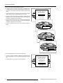
Connectors for the vertical
deflection module
Vertical scan switch
Vertical Scan Switch
One vertical switch is used for the three CRT's. See position of the
switch (diagrams) for the corresponding projector configuration.
To set the vertical scan switch :
Remove the vertical deflection module (the third module viewing
from the rear of the projector).
To remove the vertical deflection module :
Vertical deflection module
Toggle the vertical scan inversion switch to the correct position.
Reinstall the vertical deflection module.
Positions of the scan switches for the different mounting configura-
tions are illustrated on the right side.
After setting the scan switches, close the metal protection plate and
secure it with the retaining screws.
Close the top cover and reconnect the power cord to the wall outlet.
Note : Switching over from Floor to Ceiling or vice versa
requires a complete readjustment of picture geometry and
convergence.

Installation setup
4-4 5975996 BARCOGRAPHICS 808s 241197
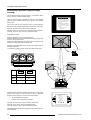
To check the current positions of the scan switches,
proceed as follows:
Attention : This procedure can only be done after power (mains)
connection. So, first continue with the projector setup
and the connections and then return to this procedure.
Switch on the projector. The projector starts up on the last
selected source.
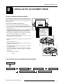
Press the <ADJUST> key.
Highlight 'SERVICE' by pushing the control stick forward or
backward and press the <ENTER> key: the 'SERVICE MODE
MENU' will be displayed.
SERVICE MODE
IDENTIFICATION
COPY A BLOCK
DELETE A BLOCK
DELETE ALL BLOCKS
CHANGE PASSWORD
CHANGE LANGUAGE
RUN TIME
DYNAMIC ASTIGMATISM
MORE...
ADJUSTMENT MODE
Select a path from
below:
Select with or
then <ENTER>
<EXIT> to return
source 1
GUIDED
RANDOM ACCESS
INSTALLATION
SERVICE
IRIS
Select with or
then <ENTER>
<EXIT> to return
Highlight 'IDENTIFICATION' by pushing the control stick forward
or backward and press the <ENTER> key.
The projector will display the 'IDENTIFICATION SCREEN'.
This screen gives the current information about the projector
configuration in the line entitled 'Config'.
All projectors leave the factory set for a ceiling/front configuration.
Proj. address : 001
Soft. Version : 5.00
Config. : Ceiling
front
Baudrate PC : 9600
Text : ON
Serial No. : 10359852

Projector setup
5-1
5975996 BARCOGRAPHICS 808s 241197
5
PROJECTOR SETUP
StdBY
MA IN POWER
PROCESSOR CYC
BLOCK MATCH
ERROR
RCU
RCVDS
PC
PA USE
PROJECTOR A DDRESS
(sum)
OFF ON
BAUD RATE TABLE
TO COMPUTER
POWER UP MODE
OPERATING MODE WHEN
POWER IS SWITCHED ON
ON
OFF
PLAYING
StdBY
PASSWORD MODE
ON
OFF
YES
NO
RESERVED
POWER UP MODE
PASSWORD MODE
BA UD RATE CODE
(sum)
PASSWORD REQUIRED
FOR ADJUSTMENT
CODE
0
1
2
3
4
5
6
7
SPEED
110
150
300
600
1200
2400
4800
9600
0
1
128
64
32
16
8
4
2
1
1
2
3
4
5
6
7
8
1
2
3
4
2
1
1
2
3
4
5
6
7
8
I
2
C SHORTED
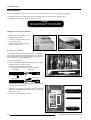
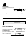
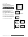
Setting the projector address
The projector's address may be set to any value between 0 and 255.
When the address is set, the projector can be controlled now by :
RCU for addresses between 0 and 9.
IBM PC (or compatible) or Apple MAC for addresses between 0 and
255.
The DIP switches on the controller board allow the SETUP of the
projector :
8 DIP switches for setting the projector address.
1 DIP switch for setting the powerup mode.
3 DIP switches for setting the baud rate for communication.
1 DIP switch for setting the password mode.
To gain access to the DIP switches :
- Open the top cover.
- Loosen the retaining screws of the metal protection plate and pivot
this plate to the lens side (Please refer to Chapter 4 'Installation
setup').
The DIP switches are located on the back side of this metal protection
plate.
Addressable with RCU
Addressable with PC, MAC
or workstation
0
9
255
PROCESS CYCLE
I
2
C SHORTED

Projector setup
5-2 5975996 BARCOGRAPHICS 808s 241197
1 128
2 64
3 32
4 16
5 8
6 4
7 2
8 1
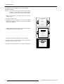
Setting the address is a hardware SETUP of your projector which
must be done during installation. Use the 8 DIP switches provided on
the controller board labelled 'Projector Address'.
Each DIP switch has its own decimal value. The sum of the values
associated to those DIP switches gives the address. As shown in the
table, if Switch No. 1 is set to ON, it represents a decimal value of 128,
Switch No.2 for 64, Switch No.3 for 32, and so forth.
In the given example, the projector address is set to 202 :
DIP switch No. : 1 2 3 4 5 6 7 8
Position ON/OFF : 1 1 0 0 1 0 1 0
Sum : 1x128 + 1x64 + 0x32 + 0x16 + 1x8 + 0x4 + 1x2 + 0x1 = 202
Factory preset address = 0
Note :
When the address button on the RCU is pressed, the projector will
display its own address on the screen. Once the address button is
pressed, to continue using your RCU, it is necessary to enter an
address, even when the displayed address is correct. Use the
numeric keys to enter the address.
For more information, please refer to the projector Owner's Manual .
1
2
3
4
5
6
7
8
0
1
OFF ON
1
2
3
4
5
6
7
8
ON
OFF
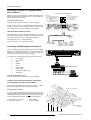
Power-up mode
OFF ON
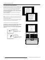
Powerup mode
The projector can start up in two different modes. The start-up mode
is determined by the position of DIP Switch No. 4 of another set of 8
DIP switches on the controller board (one set of 8 switches are used
for projector address setting).
Position of the DIP Switch No. 4 (powerup mode) :
ON : operational mode.
OFF : standby mode (Factory preset).
Source 2
Fh= 15.6 kHz
Fv= 50 Hz
Operational mode
When the power switch on the rear of the projector is pressed, the
projector displays the last selected source if available, otherwise it
remains on that source number until the source becomes available.
The on screen indication is only available when the "Text" function is
set to "ON".
Standby mode
When the power switch on the rear of the projector is pressed, the
projector starts up in the standby mode. The standby key on the RCU
is used to turn the projector ON and OFF.
Switch No Value
PROJECTOR
ADRESS
001

Projector setup
5-3
5975996 BARCOGRAPHICS 808s 241197
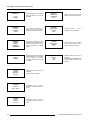
Position of DIP switches and baud rate codes :
Baud Rate for communication with a
computer
The communication speed between the projector and the computer
has 8 possible settings. With DIP Switch No. 6, No.7 and No.8 of the
8 DIP switches on the controller board, labelled as Baud rate code
(sum), it is possible to select the baud rate (communication speed).
Each DIP switch has its own decimal value. The sum of the values
associated to those DIP switches gives the baud rate code. Each
baud rate code corresponds an communication speed.
1
2
3
4
5
6
7
8
OFF
ON
0
1
Baud rate
DIP switches
4
2
1
Password mode
With DIP Switch No.5 of the second set of 8 DIP switches on the
controller board, the projector adjustments can be protected with a
password. When the password feature is enabled, the user has to
enter a password before he can enter the adjustment mode (For more
information about password setting and reprogramming the pass-
word, see Installation Adjustment).
When the password menus are disabled (adjust mode is unpro-
tected), the adjust mode can be selected by pressing the <ADJUST>
key. This position of the DIP switch is useful for qualified service
technicians because they do not need a password to enter the adjust
mode.
Position of DIP Switch No.5 :
ON : password mode enabled.
OFF : password mode disabled.
Factory preset password mode : OFF.
Factory preset baud rate = 9600
More information about computer communication with the
BARCOGRAPHICS 808s is available in the Projector Control Soft-
ware manual.
Password
mode
1
2
3
4
5
6
7
8
OFF
ON
0
1
Binary Baud rate code Speed
000 0 110
001 1 150
010 2 300
011 3 600
100 4 1200
101 5 2400
110 6 4800
111 7 9600

AC power connection
6-1
5975996 BARCOGRAPHICS 808s 241197
6
AC POWER CONNECTION
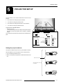
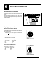
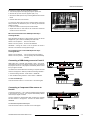
AC Power (mains) cord connection
Use the supplied cord to connect your projector to the wall outlet. Plug
the female power connector into the male connector at the back of the
projector.
This projector may be connected to an IT-power system. The IT-
power system is a power distribution system having no direct connec-
tion to earth. Instead, the exposed conductive parts of the electrical
installation are earthed.
POWE R / MAIN S COMM. PORT POR T 3
PORT 4/5
PORT 2
PORT 1
PROJECTOR MODE
POW ER / MAINS
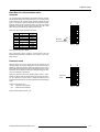
Preparing your power cord
Mains lead (power cord) with CEE7 plug
As the colors of the wires in the mains lead of this apparatus may not
correspond with the colored markings identifying the terminals in your
plug, proceed as follows:
The yellow/green wire is ground and must be connected to the
terminal in the plug which is marked by the letter E or by the safety
earth symbol or colored yellow and green.
The blue wire is neutral and must be connected to the terminal
marked with the letter N or colored black.
The brown wire is the line and must be connected to the terminal
marked with the letter L or colored red.
The wires of the delivered mains lead (power cord) are colored in
accordance with the following code :
Yellow and Green : Ground (Earth).
Blue : Neutral.
Brown : Live.
Power cord with an ANSI 73.11 plug
The wires of the delivered mains lead (power cord) are colored in
accordance with the following code :
Yellow and Green : Ground (Earth).
White : Neutral.
Black : Live.
Page is loading ...
Page is loading ...
Page is loading ...
Page is loading ...
Page is loading ...
Page is loading ...
Page is loading ...
Page is loading ...
Page is loading ...
Page is loading ...
Page is loading ...
Page is loading ...
Page is loading ...
Page is loading ...
Page is loading ...
Page is loading ...
Page is loading ...
Page is loading ...
Page is loading ...
Page is loading ...
Page is loading ...
-
 1
1
-
 2
2
-
 3
3
-
 4
4
-
 5
5
-
 6
6
-
 7
7
-
 8
8
-
 9
9
-
 10
10
-
 11
11
-
 12
12
-
 13
13
-
 14
14
-
 15
15
-
 16
16
-
 17
17
-
 18
18
-
 19
19
-
 20
20
-
 21
21
-
 22
22
-
 23
23
-
 24
24
-
 25
25
-
 26
26
-
 27
27
-
 28
28
-
 29
29
-
 30
30
-
 31
31
-
 32
32
-
 33
33
-
 34
34
-
 35
35
-
 36
36
-
 37
37
-
 38
38
-
 39
39
-
 40
40
-
 41
41


Barco Graphics 808s R9000904 User manual
- Category
- Projectors
- Type
- User manual
Ask a question and I''ll find the answer in the document
Finding information in a document is now easier with AI
Related papers
-
Cineversum BarcoGraphics 808s + Iris³ User manual
-
Barco BarcoGraphics 9300 DLC User manual
-
-
-
-
-
Barco iQ Pro R200L Owner's manual
-
Barco 72 Rear Projection System for iQ Pro Series Installation guide
-
-
Other documents
-
Infocus LP790 User manual
-
NEC NP06CM Installation And Adjustment Manual
-
PyleHome PRJSM1006 Owner's manual
-
-
-
Epson ELPMB30 User guide
-
Runco CRT Television DTV-940/943 User manual
-
 Enabling Devices Sensory Projector User manual
-
-
Strong SM-PROJ-XL-BLK Owner's manual
