Page is loading ...
Panasonic Canada Inc.
5770 Ambler Drive, Mississauga,
Ontario, L4W 2T3 Canada (905)624-5010
http://www.panasonic.ca
Panasonic Sales Company
Division of Panasonic Puerto Rico Inc.
San Gabriel Industrial Park 65th Infantry Ave. KM. 9.5 Carolina,
P.R. 00985 (809)750-4300
Panasonic System Solutions Company,
Unit Company of Panasonic Corporation of North America
Security Systems
www.panasonic.com/security
For customer support, call 1.877.733.3689
Executive Office: Three Panasonic Way 2H-2, Secaucus, New Jersey 07094
Zone Office
Eastern: Three Panasonic Way, Secaucus, New Jersey 07094
Central: 1707 N. Randal Road, Elgin, IL 60123
Southern: 1225 Northbrook Parkway, Suwanee, GA 30024
Western: 6550 Katella Ave., Cypress, CA 90630
Before attempting to connect or operate this product,
please read these instructions carefully and save this manual for future use.
FRANÇAIS ENGLISH
Color CCTV Camera
Operating Instructions
Model No. WV-CW974
Printed in Japan
© 2006 Matsushita Electric Industrial Co., Ltd. All Rights Reserved. AM1206-1017 3TR004791BAA Imprimé au Japon
WV-CW974 Cover_E/FR6mm.qxd 07.2.9 1:32 PM ページ1
ENGLISH VERSION
-2-
WARNING:
• This apparatus must be earthed.
• All work related to the installation of this apparatus should be made qualified service personnel or system installers.
• The connections should comply with local electrical code.
The serial number of this product may be found on the top
of the unit.
You should note the serial number of this unit in the space
provided and retain this book as a permanent record of your
purchase to aid identification in the event of theft.
Model No. WV-CW964
Serial No.
NOTE: This equipment has been tested and found to comply
with the limits for a Class A digital device, pursuant to Part
15 of the FCC Rules. These limits are designed to provide
reasonable protection against harmful interference when the
equipment is operated in a commercial environment. This
equipment generates, uses, and can radiate radio frequency
energy and, if not installed and used in accordance with the
instruction manual, may cause harmful interference to radio
communications.
Operation of this equipment in a residential area is likely to
cause harmful interference in which case the user will be
required to correct the interference at his own expense.
FCC Caution: To assure continued compliance, (example -
use only shielded interface cables when connecting to
computer or peripheral devices). Any changes or modifi-
cations not expressly approved by the party responsible for
compliance could void the user’s authority to operate this
equipment.
This Class A digital apparatus complies with Canadian
ICES-003.
For Canada
The lightning flash with arrowhead
symbol, within an equilateral triangle, is
intended to alert the user to the
presence of uninsulated "dangerous
voltage" within the product's enclosure
that may be of sufficient magnitude to
constitute a risk of electric shock to
persons.
The exclamation point within an
equilateral triangle is intended to alert
the user to the presence of important
operating and maintenance (servicing)
instructions in the literature accompa-
nying the appliance.
SA 1965
SA 1966
CAUTION: TO REDUCE THE RISK OF ELECTRIC SHOCK,
DO NOT REMOVE COVER (OR BACK).
NO USER-SERVICEABLE PARTS INSIDE.
REFER SERVICING TO QUALIFIED SERVICE PERSONNEL.
CAUTION
RISK OF ELECTRIC SHOCK
DO NOT OPEN
WV-CW974 Cover_E/FR6mm.qxd 07.2.9 1:32 PM ページ3

-3-
Important safety instructions
1) Read these instructions.
2) Keep these instructions.
3) Heed all warnings.
4) Follow all instructions.
5) Clean only with dry cloth.
6) Do not block any ventilation openings. Install in accordance with the manufacturer's instructions.
7) Do not install near any heat sources such as radiators, heat registers, stoves, or other apparatus (including
amplifiers) that produce heat.
8) Do not defeat the safety purpose of the polarized or grounding-type plug. A polarized plug has two blades with
one wider than the other. A grounding type plug has two blades and a third grounding prong. The wide blade or
the third prong are provided for your safety. If the provided plug does not fit into your outlet, consult an
electrician for replacement of the obsolete outlet.
9) Protect the power cord from being walked on or pinched particularly at plugs, convenience receptacles, and the
point where they exit from the apparatus.
10) Only use attachments/accessories specified by the manufacturer.
11) Use only with the cart, stand, tripod, bracket, or table specified by the manufacturer, or sold with the apparatus.
When a cart is used, use caution when moving the cart/apparatus combination to avoid injury from tip-over.
12) Unplug this apparatus during lightning storms or when unused for long periods of time.
13) Refer all servicing to qualified service personnel. Servicing is required when the apparatus has been damaged
in any way, such as power-supply cord or plug is damaged, liquid has been spilled or objects fallen into the
apparatus, the apparatus has been exposed to rain or moisture, does not operate normally, or has been
dropped.
S3125A
ENGLISH

-4-
Limitation of liability
THIS PUBLICATION IS PROVIDED “AS IS” WITHOUT
WARRANTY OF ANY KIND, EITHER EXPRESS OR
IMPLIED, INCLUDING BUT NOT LIMITED TO, THE
IMPLIED WARRANTIES OF MERCHANTABILITY,
FITNESS FOR ANY PARTICULAR PURPOSE, OR NON-
INFRINGEMENT OF THE THIRD PARTY'S RIGHT.
IN NO EVENT SHALL MATSUSHITA ELECTRIC
INDUSTRIAL CO., LTD. BE LIABLE TO ANY PARTY OR
ANY PERSON, EXCEPT FOR REPLACEMENT OR
REASONABLE MAINTENANCE OF THE PRODUCT,
FOR THE CASES, INCLUDING BUT NOT LIMITED TO
BELOW:
(1) ANY DAMAGE AND LOSS, INCLUDING WITH-
OUT LIMITATION, DIRECT OR INDIRECT, SPE-
CIAL, CONSEQUENTIAL OR EXEMPLARY,
ARISING OUT OF OR RELATING TO THE
PRODUCT;
(2) PERSONAL INJURY OR ANY DAMAGE
CAUSED BY INAPPROPRIATE USE OR NEGLI-
GENT OPERATION OF THE USER;
(3) UNAUTHORIZED DISASSEMBLE, REPAIR OR
MODIFICATION OF THE PRODUCT BY THE
USER;
THIS PUBLICATION COULD INCLUDE TECHNICAL
INACCURACIES OR TYPOGRAPHICAL ERRORS.
CHANGES ARE ADDED TO THE INFORMATION
HEREIN, AT ANY TIME, FOR THE IMPROVEMENTS OF
THIS PUBLICATION AND/OR THE CORRESPONDING
PRODUCT(S).
Disclaimer of warranty
(4) INCONVENIENCE, LOSS OR DAMAGES ARISING
IF IMAGES CANNOT BE DISPLAYED, DETECTED
OR AUTOMATICALLY DETECTED FOR ANY
REASON OR CAUSE INCLUDING ANY FAILURE
OR PROBLEM OF THE PRODUCT.
(5) ANY PROBLEM, CONSEQUENTIAL INCONVE-
NIENCE, OR LOSS OR DAMAGE, ARISING OUT
OF THE SYSTEM COMBINED BY THE DEVICES
OF THIRD PARTY.
(6) ANY CLAIM OR ACTION FOR DAMAGES,
BROUGHT BY ANY PERSON OR ORGANIZA-
TION BEING PHOTOGENIC SUBJECT, DUE TO
VIOLATION OF PRIVACY WITH THE RESULT OF
THAT SURVEILLANCE-CAMERA's PICTURE,
INCLUDING SAVED DATA, FOR SOME REA-
SON, BECOMES PUBLIC OR IS USED FOR THE
PURPOSE OTHER THAN SURVEILLANCE.
-5-
This Color CCTV Camera is a video surveillance device
that incorporates a 1/4-type {1/4"} CCD, a 30x zoom
lens, preset and pan and tilt capabilities in a dome
configuration.
■ Super Dynamic
33
(SUPER-D
33
)
SUPER-D 3 can capture clear images of subjects
whose illumination is extremely different (page 28).
■ Built-in Automatic Tracking Function
A pan, tilt, and zoom-linked automatic tracking function
ensures smooth auto tracking operations.
A mask feature helps to reduce the chance of error by
letting you mask specific parts of the image from the
detection area.
■ New DSP for High Sensitivity
A new noise reduction system lowers minimum
illuminance to 0.5 lux{fc} in the color mode and 0.04
lux{fc} in the black and white mode.
■ Auto Night time Switching to Black
and White Mode
The camera can be configured to switch to the black
and white mode automatically under low light condi-
tions for clear images, even at night.
■ Digital Flip
Normally, a camera needs to stop when it points
straight down during a tilt operation. With digital flip,
however, the camera is able to tilt from 0° to 180° in a
single motion. This makes it possible to track subjects
passing directly under the camera more smoothly.
■ Privacy Zone Function
The privacy zone function can mask specific areas of
the scene from view.
■ Patrol Function
The patrol function can store manual camera move-
ment routines for automatic playback. For example,
you can set the camera the movements of the people
to be monitored, by replaying the stored parameters
complicated move-ments are done automatically.
■ Camera Position Memory
The system can be configured with up to 256 camera
positions. A particular camera position can be selected
and viewed by entering the applicable preset number
on the system controller 10-key pad.
■ Motion Detection
The system can be configured so any motion on the
monitor screen during surveillance causes output of an
alarm signal.
This function can be used to structure a system with a
VCR that records images of nighttime intruders.
■ Internal Heating Fan
Prevents snow and frost from building up on the dome
cover.*
1
■ Waterproofing Specifications
Outdoor enclosure based on IP66*
2
of IEC60529
standard.
*1 Does not operate in environments with ambient
temperatures under -40 °C {-40 °F}. In environments
over -40 °C {-40 °F} defrosting may not function if
wind and snow are too strong. Use it with the power
on continuously to keep the temperature inside the
camera over -10 °C {14 °F}.
*2 Waterproof structure resistant to powerful jetting as
classified by the International Protection code.
Features
Standard accesories
Operating Instructions (this manual) . . . . . . . . . .1 pc.
Warranty Card . . . . . . . . . . . . . . . . . . . . . . . . . . . .1 pc.
The following items are for installation.
8P Alarm Cable . . . . . . . . . . . . . . . . . . . . . . . . . . .1 pc.
4P Alarm Cable . . . . . . . . . . . . . . . . . . . . . . . . . . .1 pc.
Connector for 24 V AC . . . . . . . . . . . . . . . . . . . . .1 pc.
Front/rear sun shield . . . . . . . . . . . . . . . . . . . . . . .1 set
Front/rear sun shield mounting screws . . . . . . . .
. . . . . . . . . . . .2 pcs. (*one screw is a spare)
Waterproof cap . . . . . . . . . . . . . . . . . . . . . . . . . .3 pcs.
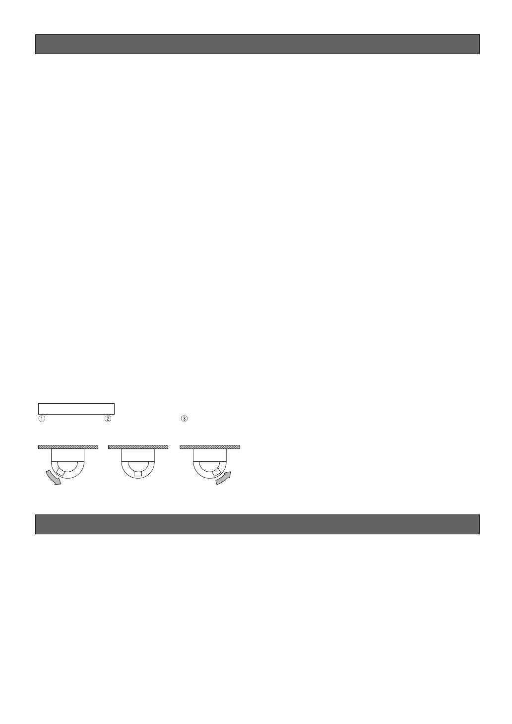
Tilting
downwards
The picture is flipped
when the camera is
pointing straight down
(at around 135°).
Tilting upwards.
· · · Digital flip is performed only when the system controller joystick is held downwards.
Digital Flip Operation
Precautions
1. Do not attempt to disassemble the camera.
To prevent electric shock, do not remove screws or
covers.
There are no user-serviceable parts inside.
Ask qualified service personnel for servicing.
2. Handle the camera with care.
Do not misuse the camera. Avoid striking, shaking,
etc. The camera could be damaged by improper
handling or storage.
3. Install the camera at a location that is able to
support its total weight.
Installing at a location that is not strong enough can
cause the camera to fall down or tip over. Be sure
to reinforce weak locations sufficiently before
installing the camera.
4. Use the fall-prevention wires to reduce the risk
of the camera falling down.
Do not detach the fall-prevention wire securing the
camera. Otherwise the camera could fall down,
causing injury to persons and damage to the
camera.
5. Never aim the camera at the sun.
Whether or not the camera is in use , never aim it at
the sun or other extremely bright objects.
Otherwise, blooming or smear may be caused.
6. Never aim the camera at strong light sources for
an extended period of time.
A light source such as a spot light causes burn-in
on the display screen. Failure to observe this may
cause the image to become discolored due to
deterioration of the color filter in the CCD.
7. Do not operate the camera beyond the specified
temperature, humidity or power source ratings.
Do not use the camera in an extreme environment
where high temperature or high humidity exists. Do
not place the camera near heat sources such as
radiators, stoves or other units that produce heat.
Use the camera under conditions where tempera-
ture is between –40 °C to +50 °C {–40 °F to 122 °F}
and humidity is below 90 %.
The input power source is 24 V AC 60 Hz.
-6-
The camera's auto tracking function operates by using
image recognition. The client is responsible for
understanding and applying the following warnings
regarding installation and operation necessary to
prevent losses due to malfunction or lack of detection
as a result of unforeseeable aspects of the installation
area.
• The camera's tracking function is for monitoring
unknown intruders. It is not suitable for locations
with large numbers of people such as intersections
or retail stores. Be sure to confirm this before
installing the camera.
• Be sure to set the height of the camera under the
detailed settings (page 41) of the auto-tracking
function.
• Install the camera in a horizontal configuration, with
the dome pointed downwards.
• Install the camera securely so that it does not sway.
High resolution operation may reduce performance.
• The camera cannot track well horizontally or directly
below itself, so avoid this type of installation.
• Install the camera and adjust the view angle so that
people do not move vertically on the screen.
Vertical motion creates only small deviation on the
screen and may not be detected.
• Dirt or scratches on the dome cover make it difficult
to see the image which may reduce performance.
Periodically clean the dome cover.
About the Auto-Tracking Function
• Rain or snow on the dome cover may reduce
performance. Consider placing the camera under
eaves or some kind of cover.
• Use the electronic sensitivity enhancement (page 29)
if using the camera at night (approximately 10 lx).
• Use the detection area mask (page 42) to avoid
detection errors caused by the motion of trees or
traffic.
• Auto-tracking may start for vehicles or other non-
human movements, however, this is not a
malfunction. Adjust the view angle or use detection
area masking (page 42).
• Adjust the view angle or use detection area
masking (page 42) if there is strong back lighting,
neon lighting or other flashing lights, or reflection on
glass or the surface of a road in the image.
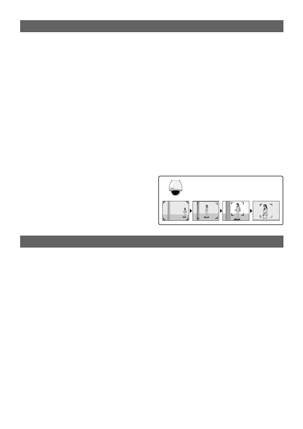
• To detect people, adjust the view angle so that the
people are about 1/5 of the vertical height of the
screen.
• Periodically replace consumable parts (page 7).
The pan, tilt and zoom functions operate in
unison to track moving subjects smoothly.

-7-
■ Operating precautions
■ What to do if OVER HEAT appears on the display.
This message indicates that the inside of the camera
has become extremely hot.
Immediately turn off the camera and contact your
retailer.
■ What to do if WARM UP-PLEASE WAIT.** appears
on the display.
This message indicates that the inside of the camera is
cold.
Please wait for a short time until the heating fan warms
up the inside of the camera.
The countdown shown as the numbers in “**” in quotes
is a guideline of the time required. When the value
reaches “0” the inside of the camera is warm and the
on-screen display disappears. The camera is then
reset and operation is normal.
■ Note the following to ensure long-term trouble-
free operation
Long operation under high temperatures and high
humidity can cause components to deteriorate and
shorten camera life.
Make sure the camera is installed in a location where it
is not directly exposed to heat from a radiator, heater,
etc.
■ About the Camera Cleaning Function
Prolonged use can lead to noise on the monitor and
divergence of preset positions.
If such conditions persist even after you perform
camera cleaning (page 40), use the special setup
menu to execute the “REFRESH” operation (page 48).
■ Do not allow anything to forcefully hit the dome
cover
Anything hitting the dome cover may damage the
camera or cause leaks.
■ CCD color filter burn-in
Intense light concentrated on one spot for a long
period can cause deterioration of the CCD internal
color filters, and discoloration of the affected part. Even
if the camera position is changed from a fixed position,
the discoloration at the previous location of the
concentrated light will remain on the screen.
■ Do not point the camera at a strong light source.
Intense light such as that produced by a spotlight
concentrated on one part of the screen can cause
blooming (rainbow around the strong light) or smearing
(vertical stripes above and below the strong light).
■ Pictures directly below the camera
A circular object appears in the center of the picture, it
is caused by the shape of the dome cover and is not a
malfunction.
■ Do not aim the camera at the same object for a
long time.
Burn-in of an image may be caused on the fluorescent
screen of CRT.
■ Handle the camera carefully.
Do not drop the camera, or subject it to strong impact
or vibration. Such conditions create the risk of
malfunction.
Smearing
Bright Subject
Blooming
8. Do not install the camera near the air outlet of an
air conditioner.
The lens may become cloudy due to condensation
if the camera is used under the following
conditions.
• Rapid temperature fluctuations by switching the air
conditioner on and off.
• Rapid temperature fluctuations due to frequent door
opening and closing.
• Use in an environment where eyeglasses become
foggy.
• Use in a room filled with cigarette smoke or dust.
If the lens becomes cloudy due to condensation,
remove the dome cover and wipe all moist surfaces
with a soft cloth.
9. Consumables
Parts having contacts such as the lens-drive
motors, cooling fan motor and slip-rings inside the
camera are subject to wear with time. Please ask
the nearest service center about replacement and
maintenance of such parts.
10.Do not aim the camera at the same object for a
long time.
Burn-in of an image may be caused on the
fluorescent screen of CRT.
11.Self-diagnosis Function
If the camera continues operating abnormally for 30
seconds or more due to such an accident as
external noise, the camera will automatically reset
its power. In the case it happens frequently, check
if there would be any environmental cause.
* Matsushita Electric Industrial Co., Ltd. herewith
declares that it will not be liable for any damage,
whether direct or indirect, caused by using the
product for business transaction or security, or
malfunctioning of this product.

-8-
■ Consumables
Parts having contacts such as the lens-drive motors,
cooling fan motor and slip-rings inside the camera are
subject to wear with time. Contact the nearest service
dealer about replacement and maintenance of such
parts.
■ Cleaning the camera
Turn off the camera and wipe it with a soft cloth. If the
camera is very dirty, wipe it off gently with a soft cloth
moistened with a weak solution of water and a neutral
kitchen detergent. Wring all excess liquid from the
cloth before wiping the camera. Next, wipe off all
remaining solution with a soft, dry cloth.
Contact a qualified service person before cleaning the
lenses. (Lenses do not move during cleaning.)
A dirty dome cover or lens causes deterioration of
picture quality. Use lens cleaning paper (like the type
available for cleaning eyeglasses or a camera lens) to
clean the lens.
The dome cover is particularly susceptible to damage.
Gently wipe it with a soft cloth.
■ Downloading (saving) or uploading (recovering)
camera setting information
Camera setting information that can be downloaded to
the system controller etc, includes existing preset
position settings and menu settings. However, the
following items are not included.
• Patrol function (page 37)
• Area title function (page 39)
• Blemish compensation pattern (page 47)
• RS485 settings (page 20)
• Password settings (page 50)
Be sure the camera is not moving and aimed at
something that moves very little (like a wall) before
downloading camera preset data to the system
controller etc. or uploading downloaded data to the
camera.
Uploading of WV-CW974 preset data to other models
(e.g. WV-CW864, WV-CW864A) may cause an error
and failure of the uploading process.
■ Self-diagnosing Function
If abnormal operation due to external noise or some
other reason continues for more than 30 seconds, the
camera will automatically reset itself and restore
normal operation. Reset operation the same
initialization routine that is performed when the camera
is turned on. If the reset is required too often, it could
mean that the camera is installed in a location where
there is a large amount of external noise. This can
cause malfunction of the camera, so you should
contact a qualified service person or system installer
as soon as possible.
■ Combining devices
There is a limit to the number of devices that can be
put together in one configuration. Check the
specifications and outer dimensions before hooking up
the devices. For more information, see the “Panasonic
CCTV System Catalogue” or consult your retailer.
■ Installation precautions
■ Be sure to perform installation work in accor-
dance with proper technical standards for electric
installation.
■ Camera Installation Location
Discuss the installation location for the camera with
your retailer, and select a wall, ceiling or other location
that is strong enough to support the installation.
■ About ceiling mounts and brackets
Bolts for mounting the ceiling mount Attachment Pipe
to a ceiling or wall are not provided.
You need to purchase them separately in accordance
with the materials and strength of the place you are
installing the camera.
• Check the installation surface, and the anchors and
bolts to be used for sufficient strength.
• Gypsum board and wood surfaces tend to be
weak, and should not be used as an installation
surface. If use of such a surface for installation is
unavoidable, be sure to take adequate measures to
reinforce the surface.
■ Tightening the Screws
• Screws should be tightened sufficiently in
accordance with the materials and structure of the
installation location.
• Do not use an impact driver to drive screws. Doing
so can damage the screws.
• Drive the screws as straight as possible. After
tightening the screws, visually inspect them to
make sure there is no unevenness and that each
screw is tight.
■ This camera is designed for use in a hanging con-
figuration only. Using it in an upright or inclined
configuration can cause malfunction and shorten
the life of the camera.
■ Install the camera in a horizontal configuration,
with the dome pointed downwards.
■ Be sure to remove this apparatus if it is not in use.
■ Never install or use the camera in the following
locations.
• Near a swimming pool or other areas where
chemicals are used
• Food preparation areas and other locations where
there are large amounts of steam vapor and oil, in
flammable atmospheres, other special environments
• Areas where radiation, X-rays, strong electric
waves, or magnetism is generated
• At sea, in coastal areas, or in areas where corrosive
gas is being generated
• Areas outside of the allowable ambient operating
temperature range (-40 °C to +50 °C {-40 °F to 122
°F})

-9-
• In a motor vehicle, on a boat, or other areas subject
to strong vibration (This camera is not designed for
use in a vehicle.)
• Near an air conditioner outlet or any areas subject to
sudden changes in temperature. (Such conditions
can cause clouding and condensation formation on
the dome cover.)
■ Remove the protective sheet from the dome cover
after the installation work is complete.
■ Wiring power to the camera
The camera does not have a power switch. During the
electrical work, configure the power supply to the
camera so it can be turned on and off.
■ Noise interference considerations
When using a power line that is greater than 120 V AC
and wiring that is longer than 1 meter, wiring should be
routed using a separate metal conduit. (The metal
conduit must be earth grounded.)
Important:
• Before setting up the camera for a configuration
where the camera's RS485 data port is used for
camera control (pan, tilt, etc.) by the system
controller, the camera's DIP switches must be
configured to specify the unit number and
communication parameters. (page 13)
If DIP switch setting is not performed, the
system controller control will not be possible
and camera setup will have to be performed
again. Be sure to check the DIP switch settings
before setting up the camera.
Note: If you need to connect a ground, be sure to do it
before you connect the main power. Also, when removing
the ground, be sure to disconnect the main power.
■ Beware of high humidity.
If the camera is installed when humidity is very high,
moisture may collect in the camera and cause the
dome to become foggy. If the dome becomes foggy,
remove it when the humidity is low and eliminate the
moisture inside the camera, and then replace the
dome. (page 6, 7)
■ About the heater
The camera comes with a built-in heater so it can be
used in cold regions. The heater automatically turns on
when the internal temperature goes below 10 °C {50
°F}. However, snow and frost that collect on the dome
cover may not melt if the temperature falls below -40
°C {-40 °F}. Care needs to be taken regarding the
ambient and internal temperature when using the
camera in cold regions.
■ About effects on image quality
The camera does not have a wiper. If the camera is
installed in the following conditions image quality may
deteriorate or the image may be invisible.
(1) In the rain
The picture may be hard to see if the wind blows
rain onto the dome cover while it is raining.
(2) In the snow
When it snows, snow may collect on the dome
cover and block some of the picture. (The amount
of snow that collects on the dome cover depends
on the quality and amount of the snow.)
(3) Effects of dust and automobile exhaust
Airborne dust and automobile exhaust, from the
location where the camera is installed, may cause
dirt to build up on the dome cover and reduce the
quality of the picture.
■ Important hints to help with the installation
• A self-cleaning function is activated (PAN/TILT/
ZOOM/FOCUS) when the camera is turned on.
• There is a limit to the number of devices that can be
put together in one configuration. Check the ratings
and outer dimensions before hooking up the
devices.

-10-
CONTENTS
Important safety instructions . . . . . . . . . . . . . . . . . . . . . . . . . . . . . . . . . . . . . . . . . . . . . . . . . .3
Limitation of liability . . . . . . . . . . . . . . . . . . . . . . . . . . . . . . . . . . . . . . . . . . . . . . . . . . . . . . . . .4
Disclaimer of warranty . . . . . . . . . . . . . . . . . . . . . . . . . . . . . . . . . . . . . . . . . . . . . . . . . . . . . . .4
Features . . . . . . . . . . . . . . . . . . . . . . . . . . . . . . . . . . . . . . . . . . . . . . . . . . . . . . . . . . . . . . . . . .5
■ Super Dynamic 3 (SUPER-D 3) . . . . . . . . . . . . . . . . . . . . . . . . . . . . . . . . . . . . . . . . . . .5
■ Built-in Automatic Tracking Function . . . . . . . . . . . . . . . . . . . . . . . . . . . . . . . . . . . . . . . . .5
■ New DSP for High Sensitivity . . . . . . . . . . . . . . . . . . . . . . . . . . . . . . . . . . . . . . . . . . . . . .5
■ Auto Night time Switching to Black and White Mode . . . . . . . . . . . . . . . . . . . . . . . . . . . .5
■ Digital Flip . . . . . . . . . . . . . . . . . . . . . . . . . . . . . . . . . . . . . . . . . . . . . . . . . . . . . . . . . . . .5
■ Privacy Zone Function . . . . . . . . . . . . . . . . . . . . . . . . . . . . . . . . . . . . . . . . . . . . . . . . . . .5
■ Patrol Function . . . . . . . . . . . . . . . . . . . . . . . . . . . . . . . . . . . . . . . . . . . . . . . . . . . . . . . . .5
■ Camera Position Memory . . . . . . . . . . . . . . . . . . . . . . . . . . . . . . . . . . . . . . . . . . . . . . . . .5
■ Motion Detection . . . . . . . . . . . . . . . . . . . . . . . . . . . . . . . . . . . . . . . . . . . . . . . . . . . . . . .5
■ Internal Heating Fan . . . . . . . . . . . . . . . . . . . . . . . . . . . . . . . . . . . . . . . . . . . . . . . . . . . . .5
■ Waterproofing Specifications . . . . . . . . . . . . . . . . . . . . . . . . . . . . . . . . . . . . . . . . . . . . . . .5
Standard accessories . . . . . . . . . . . . . . . . . . . . . . . . . . . . . . . . . . . . . . . . . . . . . . . . . . . . . . .5
About the Auto-Tracking Function . . . . . . . . . . . . . . . . . . . . . . . . . . . . . . . . . . . . . . . . . . . . . .6
Precautions . . . . . . . . . . . . . . . . . . . . . . . . . . . . . . . . . . . . . . . . . . . . . . . . . . . . . . . . . . . . . . .6
■ Operating precautions . . . . . . . . . . . . . . . . . . . . . . . . . . . . . . . . . . . . . . . . . . . . . . . . . . . .7
■ Installation precautions . . . . . . . . . . . . . . . . . . . . . . . . . . . . . . . . . . . . . . . . . . . . . . . . . . .8
Construction . . . . . . . . . . . . . . . . . . . . . . . . . . . . . . . . . . . . . . . . . . . . . . . . . . . . . . . . . . . . .11
Dip switch settings . . . . . . . . . . . . . . . . . . . . . . . . . . . . . . . . . . . . . . . . . . . . . . . . . . . . . . . .12
■ Communication Parameters (DIP Switch 2) . . . . . . . . . . . . . . . . . . . . . . . . . . . . . . . . . .12
■ Unit Number (DIP Switch 1) . . . . . . . . . . . . . . . . . . . . . . . . . . . . . . . . . . . . . . . . . . . . . .13
■ RS485 Communication Parameters (DIP Switch 1) . . . . . . . . . . . . . . . . . . . . . . . . . . . .14
■ Procedure to setup dip switch 1 . . . . . . . . . . . . . . . . . . . . . . . . . . . . . . . . . . . . . . . . . . .14
Camera installation . . . . . . . . . . . . . . . . . . . . . . . . . . . . . . . . . . . . . . . . . . . . . . . . . . . . . . . .15
■ Mounting the Camera . . . . . . . . . . . . . . . . . . . . . . . . . . . . . . . . . . . . . . . . . . . . . . . . . . .15
■ Installing the brackets . . . . . . . . . . . . . . . . . . . . . . . . . . . . . . . . . . . . . . . . . . . . . . . . . . .17
■ Attach the brackets to the camera . . . . . . . . . . . . . . . . . . . . . . . . . . . . . . . . . . . . . . . . .17
■ Attach the front and rear sun shields (provided) to the camera . . . . . . . . . . . . . . . . . . .17
Connections . . . . . . . . . . . . . . . . . . . . . . . . . . . . . . . . . . . . . . . . . . . . . . . . . . . . . . . . . . . . . .18
RS485 setup . . . . . . . . . . . . . . . . . . . . . . . . . . . . . . . . . . . . . . . . . . . . . . . . . . . . . . . . . . . . .20
Operation Examples . . . . . . . . . . . . . . . . . . . . . . . . . . . . . . . . . . . . . . . . . . . . . . . . . . . . . . . .21
Using the setup menu . . . . . . . . . . . . . . . . . . . . . . . . . . . . . . . . . . . . . . . . . . . . . . . . . . . . . .24
■ Displaying the Setup Menu . . . . . . . . . . . . . . . . . . . . . . . . . . . . . . . . . . . . . . . . . . . . . .24
■ Camera ID Settings . . . . . . . . . . . . . . . . . . . . . . . . . . . . . . . . . . . . . . . . . . . . . . . . . . . . .24
■ Scene Select Settings . . . . . . . . . . . . . . . . . . . . . . . . . . . . . . . . . . . . . . . . . . . . . . . . . . .25
■ Preset Position Settings . . . . . . . . . . . . . . . . . . . . . . . . . . . . . . . . . . . . . . . . . . . . . . . . . .25
■ Language Setting . . . . . . . . . . . . . . . . . . . . . . . . . . . . . . . . . . . . . . . . . . . . . . . . . . . . . .27
■ Advanced Menu Settings . . . . . . . . . . . . . . . . . . . . . . . . . . . . . . . . . . . . . . . . . . . . . . . .27
Camera settings . . . . . . . . . . . . . . . . . . . . . . . . . . . . . . . . . . . . . . . . . . . . . . . . . . . . . . . . . .28
■ Using the Camera Setup Menu . . . . . . . . . . . . . . . . . . . . . . . . . . . . . . . . . . . . . . . . . . .28
Pan/Tilt settings . . . . . . . . . . . . . . . . . . . . . . . . . . . . . . . . . . . . . . . . . . . . . . . . . . . . . . . . . . .33
■ Using the Pan/Tilt Setup Menu . . . . . . . . . . . . . . . . . . . . . . . . . . . . . . . . . . . . . . . . . . . .33
Auto tracking settings . . . . . . . . . . . . . . . . . . . . . . . . . . . . . . . . . . . . . . . . . . . . . . . . . . . . . . .41
■ Using the Auto Tracking Setup Menu . . . . . . . . . . . . . . . . . . . . . . . . . . . . . . . . . . . . . .41
Alarm settings . . . . . . . . . . . . . . . . . . . . . . . . . . . . . . . . . . . . . . . . . . . . . . . . . . . . . . . . . . . .44
■ Using the Alarm Setup Menu . . . . . . . . . . . . . . . . . . . . . . . . . . . . . . . . . . . . . . . . . . . . .44
Special settings . . . . . . . . . . . . . . . . . . . . . . . . . . . . . . . . . . . . . . . . . . . . . . . . . . . . . . . . . . .47
■ Using the Special Setup Menu . . . . . . . . . . . . . . . . . . . . . . . . . . . . . . . . . . . . . . . . . . . .47
Scene select setting . . . . . . . . . . . . . . . . . . . . . . . . . . . . . . . . . . . . . . . . . . . . . . . . . . . . . . .49
■ Using the Scene Select Setting Menu . . . . . . . . . . . . . . . . . . . . . . . . . . . . . . . . . . . . . .49
Password settings . . . . . . . . . . . . . . . . . . . . . . . . . . . . . . . . . . . . . . . . . . . . . . . . . . . . . . . . .50
■ Password Lock Settings . . . . . . . . . . . . . . . . . . . . . . . . . . . . . . . . . . . . . . . . . . . . . . . . .50
Shortcuts . . . . . . . . . . . . . . . . . . . . . . . . . . . . . . . . . . . . . . . . . . . . . . . . . . . . . . . . . . . . . . . .52
Troubleshooting . . . . . . . . . . . . . . . . . . . . . . . . . . . . . . . . . . . . . . . . . . . . . . . . . . . . . . . . . . .54
Specifications . . . . . . . . . . . . . . . . . . . . . . . . . . . . . . . . . . . . . . . . . . . . . . . . . . . . . . . . . . . .59
-11-
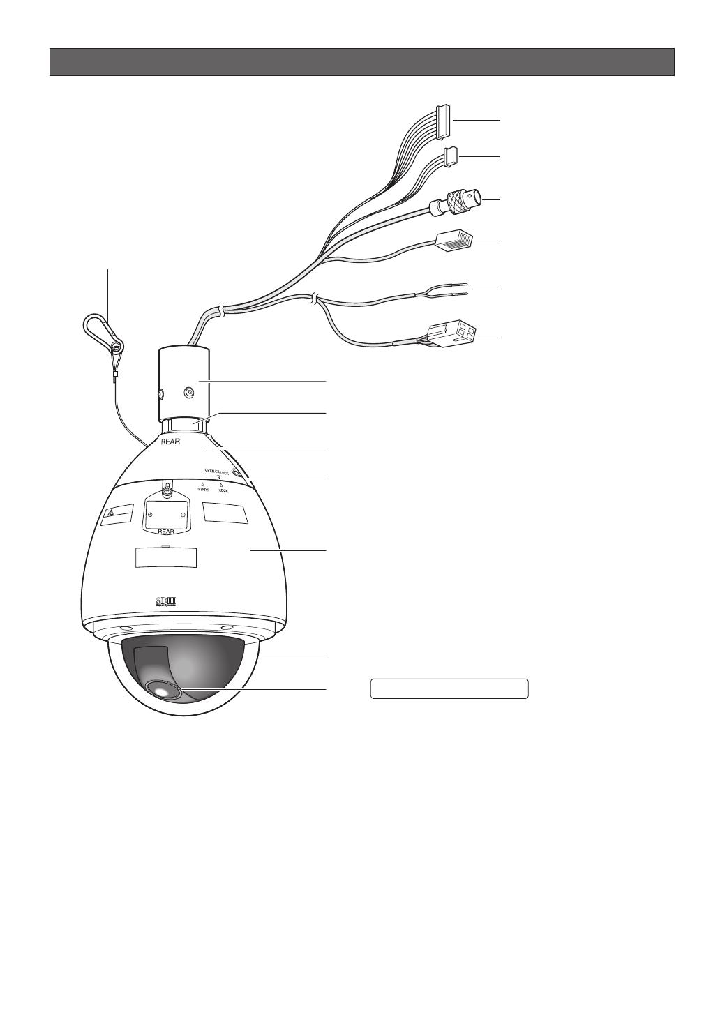
Construction
Ensuring Trouble-free Operation
• This camera uses a “slip ring” for transmission of electrical power and signals. A dirty slip ring can cause
deterioration of picture quality during panning and generation of noise.
In order to ensure trouble-free camera operation, make sure that the cleaning function (page 40) is turned on.
• If cleaning the slip ring does not eliminate poor picture quality and noise, it could mean that the slip ring has
reached the end of its service life. Contact a qualified service person or system installer to have it replaced.
Alarm Input Connector
Alarm Output Connector
Video Output Connector
Data Port
Attachment Pipe
Upper Base
Rear sun shield (provided)
Front sun shield (provided)
Sun shield (pre-attached at factory)
Dome cover (do not remove)
Lens The lens cannot replaced.
Camera Safety Wire
Power Cord
for Heater
Power Connector
Dip switch settings
In a configuration, the camera's RS485 data port is used for camera control by the system controller, the camera's
DIP switches must be configured to specify the unit number and communication parameters.
You need to set the DIP switches before installing the camera in the ceiling or on a wall.
Important:
Do not adjust the DIP switches if you are using a coaxial multiplex system, leave them off.
■ Communication Parameters (DIP Switch 2)
The factory default settings are all OFF.
Switch 1: Terminator (Internal Termination Resistance)
Set to ON in the following situations.
• When only one camera is connected.
• When only one camera is connected via a daisy chain over a long
distance.
Switches 2 to 4: Communication Parameters
This setting toggles between 2-line and 4-line communication. Use
these switches to select the communication protocol being used.
1234
ON
Terminator
Communication
Parameters
1234
ON
4-line Communication
1234
ON
2-line Communication
-12-
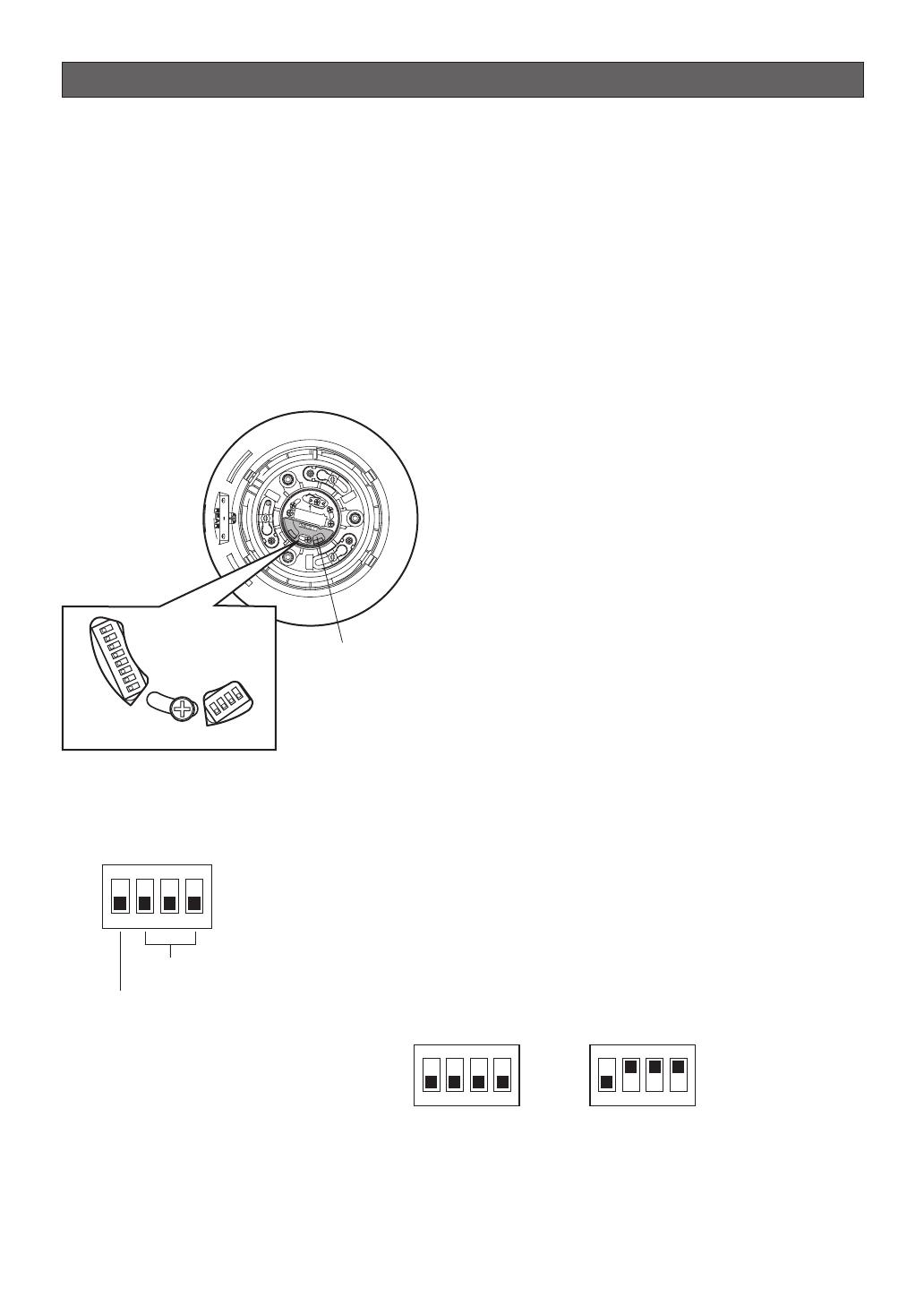
1. Attaching and removing the Upper Base
Refer to the installation manual of the mounting
brackets sold separately for installation for
removing the Upper Base.
2. Remove the protective sticker from the top of the
sun shield. (Keep the protective sticker for in step 4.)
The DIP switches can be set now.
3. Set the DIP switches as the following:
Communication parameters: Set with switch 2
Unit number: Set with switch 1
4. Put the protective sticker back over the DIP
switches.
RS485Setting
START
DIP SW1
O
N
1
2
3
4
5
6
7
8
DIP SW2
O
N
1
2
3
4
S
W
1
S
W2
Camera top view
Protective Sticker
DIP Switch
-13-
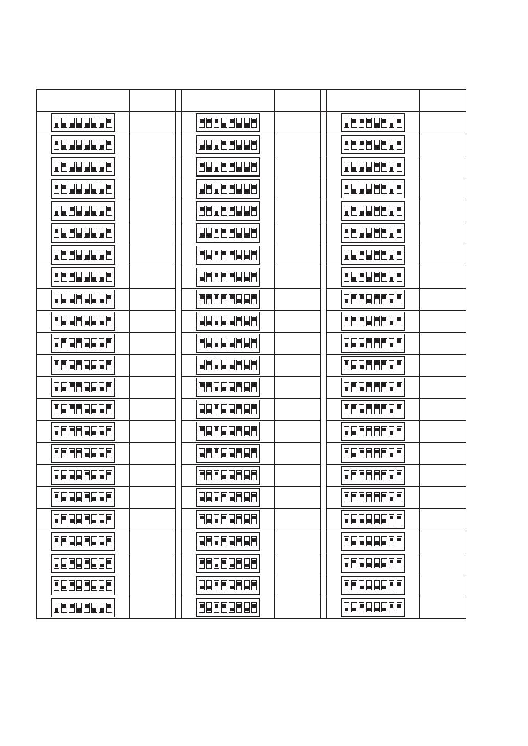
■ Unit Number (DIP Switch 1)
The factory default settings of these DIP switches are all OFF. (Coaxial Multiplex System)
Table-1
1234
ON
5678
DIP Switch 1
Unit
Number
1234
ON
5678
1234
ON
5678
1234
ON
5678
1234
ON
5678
1234
ON
5678
1234
ON
5678
1234
ON
5678
1234
ON
5678
1234
ON
5678
1234
ON
5678
1234
ON
5678
1234
ON
5678
1234
ON
5678
1234
ON
5678
1234
ON
5678
1234
ON
5678
1234
ON
5678
1234
ON
5678
1234
ON
5678
1234
ON
5678
1234
ON
5678
1234
ON
5678
1234
ON
5678
1234
ON
5678
1234
ON
5678
1234
ON
5678
1234
ON
5678
1234
ON
5678
1234
ON
5678
1234
ON
5678
1234
ON
5678
DIP Switch 1
Unit
Number
DIP Switch 1
Unit
Number
1
2
3
4
5
6
7
8
9
10
11
12
13
14
15
16
17
18
19
20
21
22
23
24
25
26
27
28
29
30
31
32
33
34
35
36
37
38
39
40
41
42
43
44
45
46
47
48
49
50
51
52
53
54
55
56
57
58
59
60
61
62
63
64
65
66
67
68
1234
ON
5678
1234
ON
5678
1234
ON
5678
1234
ON
5678
1234
ON
5678
1234
ON
5678
1234
ON
5678
1234
ON
5678
1234
ON
5678
1234
ON
5678
1234
ON
5678
1234
ON
5678
1234
ON
5678
1234
ON
5678
1234
ON
5678
1234
ON
5678
1234
ON
5678
1234
ON
5678
1234
ON
5678
1234
ON
5678
1234
ON
5678
1234
ON
5678
1234
ON
5678
1234
ON
5678
1234
ON
5678
1234
ON
5678
1234
ON
5678
1234
ON
5678
1234
ON
5678
1234
ON
5678
1234
ON
5678
1234
ON
5678
1234
ON
5678
1234
ON
5678
1234
ON
5678
1234
ON
5678
1234
ON
5678
1 ~ 96
(page 14 Note)

-14-
Notes:
• When using the Unit Number “1 ~ 96” setting, the unit number setting needs to be configured using the RS485
SET UP menu. For details about configuring this setting, see step 2 on page 20.
• Turning on power when this setting is selected causes the RS485 SET UP menu to appear during the initialization
routine.
1234
ON
5678
DIP Switch 1
Unit
Number
1234
ON
5678
1234
ON
5678
1234
ON
5678
1234
ON
5678
1234
ON
5678
1234
ON
5678
1234
ON
5678
1234
ON
5678
1234
ON
5678
1234
ON
5678
1234
ON
5678
1234
ON
5678
1234
ON
5678
1234
ON
5678
1234
ON
5678
1234
ON
5678
1234
ON
5678
DIP Switch 1
Unit
Number
DIP Switch 1
Unit
Number
69
70
71
72
73
74
75
76
77
78
79
80
81
82
83
84
85
86
87
88
89
90
91
92
93
94
95
1234
ON
5678
1234
ON
5678
1234
ON
5678
1234
ON
5678
1234
ON
5678
1234
ON
5678
1234
ON
5678
1234
ON
5678
1234
ON
567
8
■ RS485 Communication Parameters (DIP Switch 1)
Configuring DIP Switch 1 as shown below resets communication parameters to their factory default settings. You can
then change the settings as desired.
Table-2
1234
ON
5678
DIP Switch 1 Setting Description
1234
ON
5678
1234
ON
5678
1234
ON
5678
This setting resets communication parameters to the factory default settings.
BAUD RATE : 19 200 bit/s, DATA BIT : 8 bit, PARITY CHECK : NONE, STOP BIT : 1 bit
BAUD RATE : 9 600 bit/s, DATA BIT : 8 bit, PARITY CHECK : NONE, STOP BIT : 1 bit
BAUD RATE : 4 800 bit/s, DATA BIT : 8 bit, PARITY CHECK : NONE, STOP BIT : 1 bit
ON
■ Procedure to setup dip switch 1
(1) Turn off the camera and use DIP Switch 1 to configure RS485 Communication Parameters as shown in Table-2.
(2) Turn on the camera.
This applies the setting you configured in step (1).
(3) Turn off the camera, use DIP Switch 1 to set the unit number (as shown in Table-1), and then turn the camera
back on again.
Camera installation
-15-
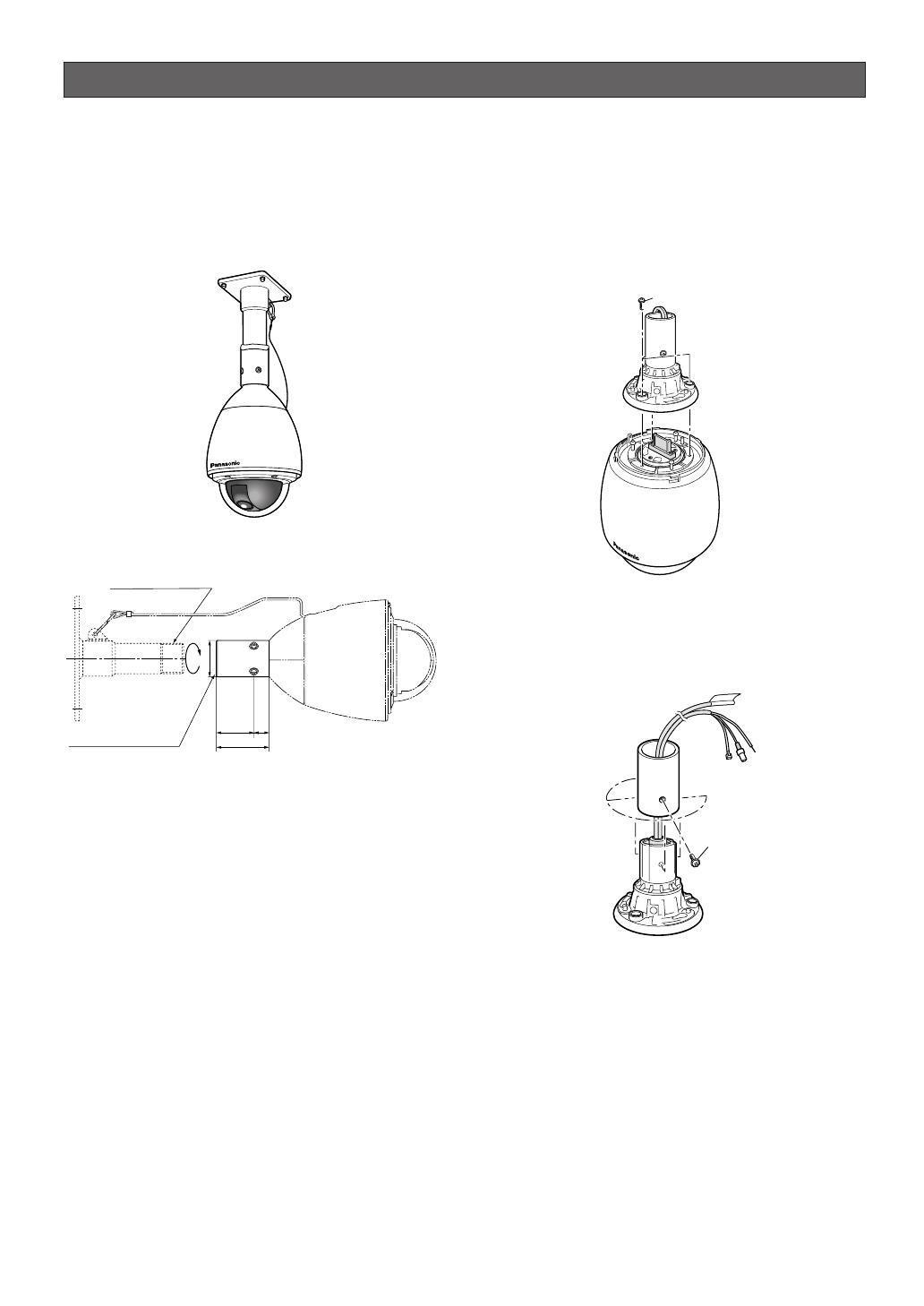
■ Mounting the Camera
Ceiling mount
The figure shows an example of the camera mounted
on a ceiling with a locally procured bracket.
Refer to the instructions included with the bracket for
filling gaps and holes with waterproof material.
● Construction
● Assemble procedure
1. Preparations
(1) Procure a ceiling mount bracket.
(2) To prevent the camera from falling, use a
mounting a bracket to which a safety wire can
be attached.
(3) Installation Surface
Caution: Consult an expert on the load bearing
capacity of the installation surface and
structure. If the surface is not strong enough,
the camera may fall down. Refer to the
product specifications for weights.
Prepare appropriate hardware (e.g. wall nuts,
anchor bolts, etc.) for fixing on the installation
surface.
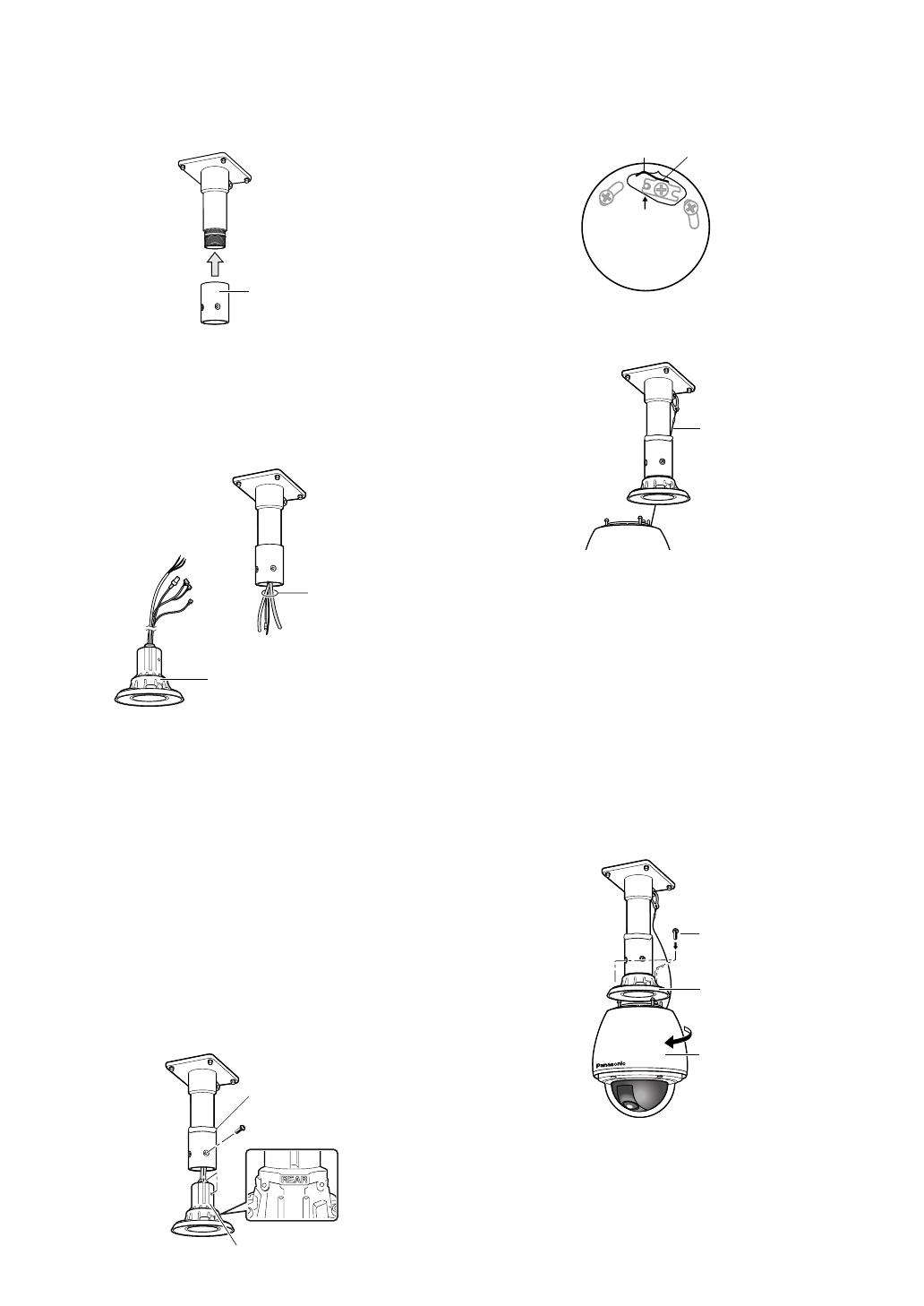
2. Disassembling the Camera
(1) Remove the upper base from the camera by
loosening 3 screws. The screws that are
removed need to be used during reassembly.
Be careful to not lose them. Turn the upper base
and separate it.
* Special screw (mounting screw): Use a
hexagon wrench for the hexagon screw (M6).
(2) Remove the attachment pipe from the upper
base by loosening 4 screws.
* Special screw (mounting screw): Use a
hexagon wrench for the hexagon screw (M6).
(Ø58)
(60)
25
85
40 1-1/2A deep 30 MAX
PT11 crest (parallel pipe thread)
40 1-1/2B deep 30 MAX
PT11 crest (taper pipe thread)
x3
x4
4. Mounting the camera
(1) Aim the "START" arrow at the bent portion of the
leaf spring.
(2) Be sure to hook the fall prevention wire into the
bracket.
(3) Fix the camera to the upper base.
• Move the camera up so that its guide pins fit
into the guide holes of the upper base.
• Turn the camera counter-clockwise to the
end, viewed from the bottom.
• Fasten 3 screws (the screws that were
removed in step (1) of “2. Disassembling the
Camera”).
Caution: Tighten the three (3) mounting screws
for the upper base.
Recommended torque: Approximately 5.0
N/m {51 kgf cm}
Poorly tightened screws may result in water
leaking into the camera or possible fire.
3. Mounting the Bracket
(1) Fix the bracket to the installation surface using
appropriate bolts, nuts or the like (not supplied).
Make sure that everything is tightened securely.
(2) Fix the attachment pipe to the bracket.
(3) Thread cables through the bracket. Connect
cables, referring to CONNECTIONS.
Warning: Seal the cables with plastic or rubber
tape to prevent it from being exposed.
(4) Fix the upper base to the attachment pipe.
• Fasten 4 screws (the screws that were
removed in step (2) of "2. Disassembling the
Camera") making sure that "REAR" engraved
on the upper base faces the wall.
Recommended torque: Approximately 5.0
N/m {51 kgf cm}
• Fill the gap between the bracket and
attachment pipe with waterproof material
such as silicon clay. See instructions of the
bracket for details.
Warning: Carefully apply the sealing so that
water or moisture cannot get inside. If water
gets inside the camera it could cause a
shock or fire. Also, if moisture gets inside the
camera it could cause the dome to become
foggy.
Attachment Pipe
Cables
Upper Base
Upper Base
x4 Screws
Waterproof Material
START
Leaf Spring
Bending
Fall Prevention
Wire
x3 Screws
Enclosure
Upper Base
-16-
■ Installing the brackets
Refer to the installation guides provided with the
brackets.
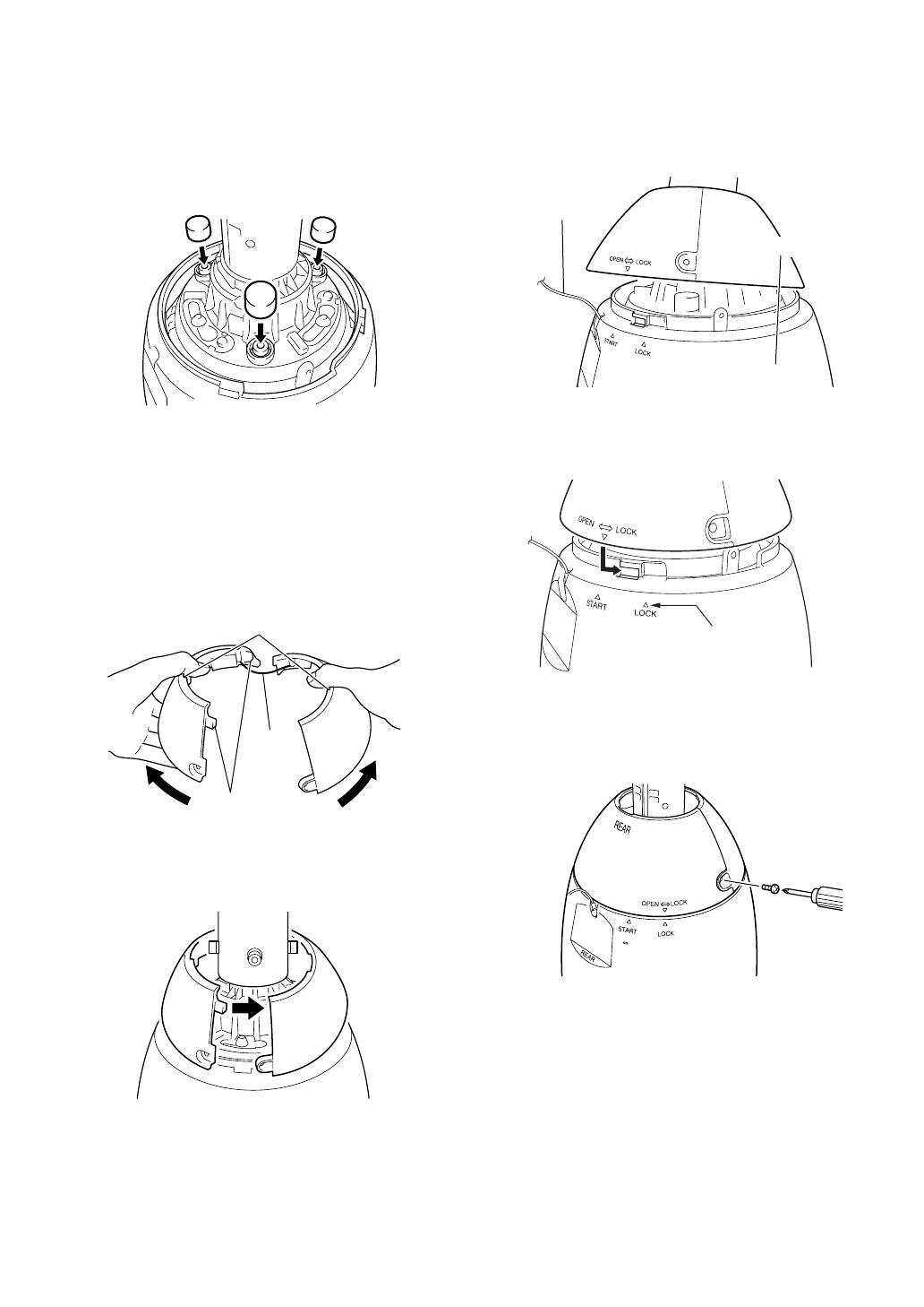
■ Attach the brackets to the camera
1. Put the waterproof caps (provided) onto the tops of
the screws.
■ Attach the front and rear sun
shields (provided) to the camera
1. Hold the front and rear sun shields by the
indentations on the rims and release the hooks from
both sides to separate them.
A wire is attached to one side to prevent them from
being lost.
2. Hold the front and rear sun shields near the Upper
Base in position to be mounted.
3. Before clamping the sun shield, close the front and
rear sun shields (first latch the hook on the wire
side, and then do the other side).
* Take care that the camera safety wire does not go
on the inside.
4. Align the arrow ( ) on the rear sun shield with the
"START" arrow ( ) on the sun shield and then turn
them to the “LOCK” arrow ( ) until they click.
5. Use the screws on the front/rear sun shields to
attach them to the camera.
Recommended tightening torque: 5.0 N/m {51 kgf
cm}
Note: To remove the front/rear sunshields from the
camera, do the above procedure in reverse.
Caution: The camera safety wire is designed to allow
the camera to hang from it. Do not apply force greater
than the weight of the camera to the wire.
-17-
Wire
Unhook
Indented parts
Sun shield
Camera
Safety wire
Align with this arrow
Pin no. Power source
1
2
3
4
24 V AC LIVE
24 V AC NEUTRAL
Ground
Not use
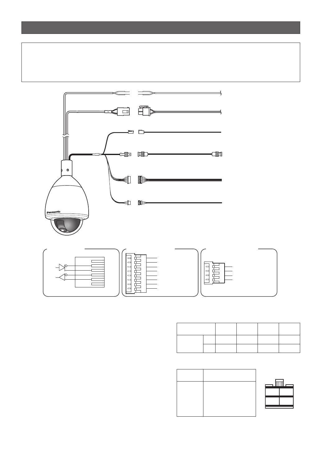
Connections
-18-
RS485 Data Port
Alarm Input Connector
Alarm Output Connector
T(B)
T(A)
R(B)
R(A)
Red
Orange
Yellow
Green
Data
Tx
Data
Rx
(RJ-12)
Alarm In 2 (Red)
Alarm In 1 (Black)
GND (Brown)
Alarm In 3 (Yellow)
Alarm In 4 (Blue)
GND (Orange)
GND (
Light Blue or Green
)
GND (Violet)
Alarm Out 2 (Pink)
Alarm Out 1 (Grey)
GND (White)
GND (Light Green
or Light Blue)
Separate 2-wire
24 V AC
Coaxial Cable (5C-2V)*2
24 V AC Cable for camera
24 V AC Cable for Heater
RS485 Data Port
To VIDEO IN port
(CAMERA IN)
8P Alarm Cable (provided)
4P Alarm Cable (provided)
To sensor, etc.
To buzzer,
display device, etc.
To Matrix Switcher,
etc.
Video Output
Connector
Alarm Input
Connector
Alarm Output
Connector
Twisted Pair Cable*1
(BNC)
(RJ-12)
*1: For twisted pair cable, use shielded low-impedance cable with a thickness of at least AWG#22
(0.33 mm
2
).
*2: Keep the overall length of coaxial cable under 1200 meters (in the case of 5C-2V).
For details, see the operating instructions for the Panasonic system equipment you are going to
connect.
*3: Be sure to connect the grounding cable to ground.
Alarm In/Out Ratings
Alarm In : 5 V DC pull-up input. Drive capacity of at
lease 0.2 mA required.
OFF : 4 V DC minimum 5 V DC maximum,
or open
ON : 1 V DC maximum or short
Alarm Out : Open collector output. 16 V DC, 100 mA
maximum drive capacity
OFF : Open
ON : 100 mA maximum
* When connecting to an external device, set up the
system so the ratings are not exceeded.
Note: Do not turn off camera power within 30 seconds
after turning it on. Doing so can cause pan, tilt, zoom,
or focus to go out of position.
Precautions
• The following connections should be made by qualified service personnel or system installers in accordance
with all local codes.
• Turn off the power at the fuse box before starting the installation work, or it so could result in fire, electric shock,
personal injury, and material damage.
#24
(0.22mm
2
)
Copper wire size
(AWG)
Length
of cable
(approx.)
(m)
(ft)
#22
(0.33mm
2
)
#20
(0.52mm
2
)
#18
(0.83mm
2
)
20 30 45 75
65 100 160 260
• 24 V AC Power Supply Connection
Recommended wire gauge sizes for 24 V AC line
Accessory Connector Information
1
3
2
4
-19-
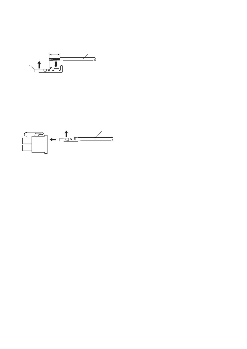
Contact
Insert
Up
A
Approx.
3 mm {0.1"}
Insert the wire until A position
and clamp the contacts.
Wire
Up
Contact
Wire
Approx.
3 mm {0.1"}
Insert the wire until A position
and clamp the contacts.
Contact
Up
Wire
How to Assemble the Cable with the Accessory
Connector
Strip back the cable jacket approx. 3 mm {0.1"} and
separate the individual conductors.
Prepare the individual conductors for clamping. Use
MOLEX band tool part number 57027-5000 (for UL-
Style Cable UL1015) or 57026-5000 (for UL-Style
UL1007) for clamping the contacts.
After clamping the contacts, push them into the proper
holes in the accessory connector of this camera until
they snap in place.
Cautions:
• Shrinking the cable-entry seal is a one-time
procedure. Do not shrink the cable-entry seal until
ascertaining that the unit is functioning.
• CONNECT THIS TO 24 V AC CLASS 2 POWER
SUPPLY ONLY.

RS485 setup
The following procedure is to configure the RS485
setup when using the system controller to control the
camera (pan, tilt, etc.) via the camera's data port.
1. Display the setup menu (page 24), move the cursor
to COMMUNICATION O, and then press the CAM
(SET) button.
This will display the RS485 setup menu.
2. Check the unit number. (page 13)
The UNIT NUMBER item shows the unit number
specified by DIP Switch 1. The factory default unit
number is 1.
If DIP Switch 1 specifies 1 to 96 as the unit number,
move the cursor to UNIT NUMBER and then tilt the
joystick left or right to select a unit number (1 to 96).
Note: It is not necessary to configure the RS485
SET UP menu SUB ADDRESS setting.
3. Move the cursor to BAUD RATE, and then tilt the
joystick left or right to select a baud rate setting.
Tilting the joystick cycles through the baud rate
(transmission speed) display in the sequence
shown below. (unit: bits/s) The factory default
setting is 19200.
4. Move the cursor to DATA BIT, and then tilt the
joystick left or right to select a data bit setting (7 or
8).
The factory default setting is 8.
5. Move the cursor to PARITY CHECK, and then tilt the
joystick left or right to select a parity bit setting
(NONE, ODD, EVEN).
The factory default setting is NONE.
6. Move the cursor to STOP BIT, and then tilt the
joystick left or right to select a stop bit setting (1 or
2).
The factory default setting is 1.
7. Move the cursor to XON/XOFF, and then tilt the
joystick left or right to select an XON/XOFF setting.
The factory default setting is NOT USE.
NOT USE: Disables X ON/X OFF data flow control.
USE : Enables X ON/X OFF data flow control.
8. Move the cursor to WAIT TIME, and then tilt the
joystick left or right to select a wait time setting.
The wait time is the time that the camera should
wait before resending data when no receive
acknowledgement (ACK) is returned after data is
sent.
Tilting the joystick cycles through the wait time
display in the sequence shown below. (unit: ms)
The factory default setting is OFF.
9. Move the cursor to ALARM DATA, and then tilt the
joystick left or right to select an alarm data send
mode setting.
POLLING : Sends alarm data in response to a
request by the system controller.
AUTO1 : Sends alarm data each time an alarm
signal is input.
AUTO2 : Sends alarm data at five-second intervals.
This is the factory default setting.
10.Move the cursor to DELAY TIME, and then tilt the
joystick left or right to select a delay time setting.
The delay time is the time is the time the camera
should wait before sending a receive acknowledge
(ACK). The delay time display changes in the
sequence shown below. (unit: ms) The factory
default setting is OFF.
This setting can be configured only when 2-line
configuration is selected by DIP Switch 2. (page 12)
-20-
** RS485 SETUP **
UNIT NUMBER
SUB ADDRESS
BAUD RATE
DATA BIT
PARITY CHECK
STOP BIT
XON/XOFF
WAIT TIME
ALARM DATA
DELAY TIME
RET TOP
1
-----
19200
8
NONE
1
NOT USE
OFF
AUTO2
OFF
2400 4800 9600 19200
OFF ↔ 100MS ↔ 200MS ↔ 400MS ↔ 1000MS
OFF ↔ 100MS
/