
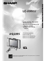
LIQUID CRYSTAL TELEVISION
TÉLÉVISEUR ACL
TELEVISOR CON PANTALLA DE
CRISTAL LÍQUIDO
TELEVISOR DE CRISTAL
LÍQUIDO
LC-20B6U
OPERATION MANUAL
MODE D’EMPLOI
MANUAL DE OPERACIÓN
MANUAL DE OPERAÇÃO
Products that have earned the ENERGY STAR
®
are designed to protect the environment
through superior energy efficiency.
ENGLISH
FRANÇAIS
ESPAÑOL
PORTUGUÊS

1
LC-20B6U
LIQUID CRYSTAL TELEVISION
OPERATION MANUAL
IMPORTANT:
To aid reporting in case of loss or theft, please record the
TV’s model and serial numbers in the space provided. The
numbers are located at the rear of the TV.
Model No.:
Serial No.:
ENGLISH
ENGLISH
FRANÇAIS
ESPAÑOL
IMPORTANT INFORMATION
WARNING: TO REDUCE THE RISK OF FIRE OR ELECTRIC SHOCK, DO NOT EXPOSE
THIS PRODUCT TO RAIN OR MOISTURE.
CAUTION
RISK OF ELECTRIC SHOCK
DO NOT OPEN
CAUTION: TO REDUCE THE RISK OF ELECTRIC SHOCK,
DO NOT REMOVE COVER (OR BACK).
NO USER-SERVICEABLE PARTS INSIDE.
REFER SERVICING TO QUALIFIED SERVICE
PERSONNEL.
The lightning flash with arrow-head symbol,
within an equilateral triangle, is intended to
alert the user to the presence of uninsulated
“dangerous voltage” within the product’s
enclosure that may be of sufficient magnitude
to constitute a risk of electric shock to persons.
The exclamation point within a triangle is
intended to alert the user to the presence of
important operating and maintenance (servic-
ing) instructions in the literature accompanying
the product.
U.S.A. ONLY
The enclosed RGB cable must be used with the device. The cable is provided to ensure that the device complies with FCC
Rules.
U.S.A. ONLY

2
IMPORTANT INFORMATION (Continued)
WARNING: FCC Regulations state that any unauthorized changes or modifications to this equipment not expressly
approved by the manufacturer could void the user’s authority to operate this equipment.
CAUTION: TO PREVENT ELECTRIC SHOCK, MATCH WIDE BLADE OF PLUG TO WIDE
SLOT, FULLY INSERT.
U.S.A. ONLY
CAUTION:
DO NOT PLACE THIS PRODUCT ON AN UNSTABLE CART, STAND, TRIPOD, BRACKET, OR TABLE.
THE PRODUCT MAY FALL CAUSING SERIOUS PERSONAL INJURY AND SERIOUS DAMAGE TO
THE PRODUCT. USE ONLY WITH A CART, STAND, TRIPOD, BRACKET, OR TABLE RECOMMENDED
BY THE MANUFACTURER OR SOLD WITH THE PRODUCT. FOLLOW THE MANUFACTURER’S
INSTRUCTIONS WHEN INSTALLING THE PRODUCT AND USE MOUNTING ACCESSORIES
RECOMMENDED BY THE MANUFACTURER. A PRODUCT AND CART COMBINATION SHOULD
BE MOVED WITH CARE. QUICK STOPS, EXCESSIVE FORCE, AND UNEVEN SURFACES MAY CAUSE
THE PRODUCT AND CART COMBINATION TO OVERTURN.
“Note to CATV system installer: This reminder is provided to call the CATV system installer’s attention to Article 820-40 of the National
Electrical Code that provides guidelines for proper grounding and, in particular, specifies that the cable ground shall be connected to the
grounding system of the building, as close to the point of cable entry as practical.”
This product utilizes tin-lead solder, and fluorescent lamp containing a small amount of mercury. Disposal of these materials
may be regulated due to environmental considerations. For disposal or recycling information, please contact your local
authorities or the Electronic Industries Alliance: www.eia.org
INFORMATION:
This equipment has been tested and found to comply with the limits for a Class B digital device, pursuant to
Part 15 of the FCC Rules. These limits are designed to provide reasonable protection against harmful
interference in a residential installation. This equipment generates, uses and can radiate radio frequency
energy and, if not installed and used in accordance with the instructions, may cause harmful interference to
radio communications. However, there is no guarantee that interference will not occur in a particular
installation. If this equipment does cause harmful interference to radio or television reception, which can be determined
by turning the equipment off and on, the user is encouraged to try to correct the interference by
one or more of the following measures:
—Reorient or relocate the receiving antenna.
—Increase the separation between the equipment and receiver.
—Connect the equipment into an outlet on a circuit different from that to which the receiver is connected.
—Consult the dealer or an experienced radio/TV technician for help.
DECLARATION OF CONFORMITY
SHARP LIQUID CRYSTAL TELEVISION, MODEL LC-20B6U.
This device complies with Part 15 of the FCC Rules. Operation is subject to the following two conditions:
(1) This device may not cause harmful interference, and (2) this device must accept any interference
received, including interference that may cause undesired operation.
RESPONSIBLE PARTY:
SHARP ELECTRONICS CORPORATION
Sharp Plaza, Mahwah, New Jersey 07430-2135
TEL: 1-800-BE-SHARP
For Business Customers: URL
http://www. sharpusa. com
Trademark
• Micronas
®
VOICE is a Speech Enhancement and Intelligibility Processing technology by Micronas GmbH.
• Micronas is a trademark of Micronas GmbH.
U.S.A. ONLY
U.S.A. ONLY
U.S.A. ONLY

3
DEAR SHARP CUSTOMER
Thank you for your purchase of the Sharp Liquid Crystal Television. To ensure safety and many years
of trouble-free operation of your product, please read the Important Safety Precautions carefully before
using this product.
IMPORTANT SAFETY PRECAUTIONS
Electricity is used to perform many useful functions, but it can also cause personal injuries and property damage if
improperly handled. This product has been engineered and manufactured with the highest priority on safety. However,
improper use can result in electric shock and/or fire. In order to prevent potential danger, please observe the following
instructions when installing, operating and cleaning the product. To ensure your safety and prolong the service life of your
LCD color TV product, please read the following precautions carefully before using the product.
■ Read instructions—All operating instructions must be read and understood before the product is operated.
■ Keep this manual in a safe place—These safety and operating instructions must be kept in a safe place for future
reference.
■ Observe warnings—All warnings on the product and in the instructions must be observed closely.
■ Follow instructions—All operating instructions must be followed.
■ Attachments—Do not use attachments not recommended by the manufacturer. Use of inadequate attachments
can result in accidents.
■ Power source—This product must operate on a power source specified on the specification label. If you are not
sure of the type of power supply used in your home, consult your dealer or local power company. For units
designed to operate on batteries or another power source, refer to the operating instructions.
■ Power cord protection—The power cords must be routed properly to prevent people from stepping on them or
objects from resting on them. Check the cords at the plugs and product.
■ If the AC adapter is misplaced or needs to be replaced, obtain the same type of adapter from a SHARP service
center or your dealer.
■ Overloading—Do not overload AC outlets or extension cords.
Overloading can cause fire or electric shock.
■ Entering of objects and liquids—Never insert an object into the product through vents or openings. High voltage
flows in the product, and inserting an object can cause electric shock and/or short internal parts. For the same
reason, do not spill water or liquid on the product.
■ Servicing—Do not attempt to service the product yourself. Removing covers can expose you to high voltage and
other dangerous conditions. Request a qualified service person to perform servicing.
■ Repair—If any of the following conditions occurs, unplug the power cord from the AC outlet, and request a quali-
fied service person to perform repairs.
a.When the power cord or plug is damaged.
b.When a liquid was spilled on the product or when objects have fallen into the product.
c. When the product has been exposed to rain or water.
d.When the product does not operate properly as described in the operating instructions.
Do not touch the controls other than those described in the operating instructions. Improper adjustment of
controls not described in the instructions can cause damage, which often requires extensive adjustment work by
a qualified technician.
e.When the product has been dropped or damaged.
f. When the product displays an abnormal condition. Any noticeable abnormality in the product indicates that the
product needs servicing.
■ Replacement parts—In case the product needs replacement parts, make sure that the service person uses
replacement parts specified by the manufacturer, or those with the same characteristics and performance as the
original parts. Use of unauthorized parts can result in fire, electric shock and/or other danger.
■ Safety checks—Upon completion of service or repair work, request the service technician to perform safety checks
to ensure that the product is in proper operating condition.
■ Wall or ceiling mounting—When mounting the product on a wall or ceiling, be sure to install the product according
to the method recommended by the manufacturer.
■ Polarization—This AC adapter may be equipped with a polarized alternating current line plug (a plug having one
blade wider than the other). This plug will fit into the power outlet only one way. This is a safety feature. If you are
unable to insert the plug fully into the outlet, try reversing the plug. If the plug should still fail to fit, contact your
electrician to replace your obsolete outlet.
Do not defeat the safety purpose of the polarized plug.

4
IMPORTANT SAFETY PRECAUTIONS (Continued)
■ The Liquid Crystal panel is a very high technology product with 2,359,296 thin film transistors, giving you fine picture
details.
Occasionally, a few non-active pixels may appear on the screen as a fixed point of blue, green or red.
Please note that this does not affect the performance of your product.
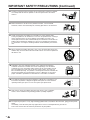
■ Cleaning—Unplug the power cord from the AC outlet before cleaning the product.
Use a damp cloth to clean the product. Do not use liquid cleaners or aerosol
cleaners.
■ Water and moisture—Do not use the product near water, such as bathtub,
washbasin, kitchen sink and laundry tub, swimming pool and in a wet basement.
■ Stand—Do not place the product on an unstable cart, stand, tripod or table.
Placing the product on an unstable base can cause the product to fall, resulting in
serious personal injuries as well as damage to the product. Use only a cart,
stand, tripod, bracket or table recommended by the manufacturer or sold with the
product. When mounting the product on a wall, be sure to follow the manufactur-
er’s instructions. Use only the mounting hardware recommended by the manufac-
turer.
■ When relocating the product placed on a cart, it must be moved with utmost care.
Sudden stops, excessive force and uneven floor surface can cause the product to
fall from the cart.
■ Ventilation—The vents and other openings in the cabinet are designed for
ventilation. Do not cover or block these vents and openings since insufficient
ventilation can cause overheating and/or shorten the life of the product. Do not
place the product on a bed, sofa, rug or other similar surface, since they can
block ventilation openings. This product is not designed for built-in installation; do
not place the product in an enclosed place such as a bookcase or rack, unless
proper ventilation is provided or the manufacturer’s instructions are followed.
■ The Liquid Crystal panel used in this product is made of glass. Therefore, it can
break when the product is dropped or applied with impact. Be careful not to be
injured by broken glass pieces in case the Liquid Crystal panel breaks.
■ Heat sources—Keep the product away from heat sources such as radiators,
heaters, stoves and other heat-generating products (including amplifiers).

5
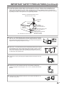
■ If an outside antenna is connected to the television equipment, be sure the antenna system is grounded so as to
provide some protection against voltage surges and built-up static charges. Section 810 of the National Electrical
Code provides information with respect to proper grounding of the mast and supporting structure, grounding of the
lead-in wire to an antenna discharge unit, size of grounding conductors, location of antenna-discharge unit, connection
to grounding electrodes, and requirements for the grounding electrode.
■ Power Lines – An outside antenna system should not be located in the vicinity of
overhead power lines or other electric light or power circuits, or where it can fall
into such power lines or circuits. When installing an outside antenna system,
extreme care should be taken to keep from touching such power lines or circuits
as contact with them might be fatal.
ANTENNA
LEAD IN
WIRE
ANTENNA
DISCHARGE UNIT
(NEC SECTION 810-20)
GROUNDING CONDUCTORS
(NEC SECTION 810-21)
GROUND CLAMPS
POWER SERVICE GROUNDING
ELECTRODE SYSTEM
(
NEC ART 250, PART H
)
ELECTRIC
SERVICE
EQUIPMENT
NEC—NATIONAL ELECTRICAL CODE
GROUND
CLAMP
EXAMPLE OF ANTENNA GROUNDING AS PER
NATIONAL ELECTRICAL CODE
■ Lightning – For added protection for this television equipment during a lightning
storm, or when it is left unattended and unused for long period of time, unplug it
from the wall outlet and disconnect the antenna. This will prevent damage to the
equipment due to lightning and power-line surges.
■ To prevent fire, never place any type of candle or flames on the top or near the
TV set.
■ To prevent fire or shock hazard, do not expose this products to dripping or
splashing. No objects filled with liquids, such as vases, should be placed on the
products.
■ To prevent fire or shock hazard, do not place the AC power cord under the TV
set or other heavy items.
IMPORTANT SAFETY PRECAUTIONS (Continued)

6
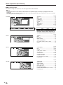
Contents
IMPORTANT INFORMATION ............................................ 1
Trademark ......................................................................... 2
DEAR SHARP CUSTOMER .............................................. 3
IMPORTANT SAFETY PRECAUTIONS ............................ 3
Supplied Accessories ...................................................... 7
Preparation ....................................................................... 8
Installing Batteries in the Remote Control ................... 8
Using Remote Control ................................................. 8
Antenna Connection ................................................... 9
Removing the Terminal Cover ..................................... 9
Power Connection ..................................................... 10
Part Names of Main Unit ................................................ 11
Listening with Headphones....................................... 11
How to Fix the Cables ............................................... 12
Part Names of Remote Control ..................................... 13
TV Signals in Your Region ............................................ 13
EZ SETUP (With AUTO CLOCK Setting) ...................... 14
EZ SETUP during the First Power On ........................ 14
Setting the CLOCK ......................................................... 15
AUTO CLOCK Setting ............................................... 15
MANUAL CLOCK Setting .......................................... 16
TIME DISPLAY ........................................................... 16
Basic Operation.............................................................. 17
Turning On and Off the Main Power .......................... 17
Standby ..................................................................... 17
Switching the Input Modes
(AV1/AV2/COMPONENT/PC/TV) ......................... 17
Sound Volume ........................................................... 18
Changing Channels .................................................. 18
Selecting Menu Items................................................ 19
Basic Adjustment Settings ............................................ 21
AV MODE .................................................................. 21
OPC ........................................................................... 22
BACKLIGHT .............................................................. 22
PICTURE Adjustments .............................................. 23
COLOR TEMPERATURE ........................................... 23
I/P SETTING .............................................................. 24
NOISE CLEAN ........................................................... 24
FILM MODE ............................................................... 24
QUICK SHOOT.......................................................... 24
Useful Features .............................................................. 25
AUDIO Adjustments .................................................. 25
WIDE SOUND............................................................ 25
SPEECH EMPHASIS.................................................. 25
PC SOUND SELECT (for PC mode) .......................... 26
CH-SETTING ............................................................. 26
SETUP ....................................................................... 28
COMP. 2/AV1 SELECT ............................................... 28
V-CHIP Settings ......................................................... 29
CLOSED CAPTION ................................................... 35
VIEW MODE .............................................................. 36
AUDIO ONLY ............................................................. 36
SLEEP TIMER ............................................................ 37
WAKE-UP TIMER ....................................................... 38
NO SIGNAL OFF ....................................................... 38
NO OPERATION OFF ................................................ 38
PICTURE FLIP ........................................................... 39
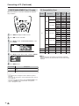
Connecting a PC ............................................................ 40
Viewing an Image from a PC ..................................... 40
Displaying an Image from a PC ................................ 40
INPUT SIGNAL (for PC mode) .................................. 41
FINE SYNC. Adjustments (for PC mode) .................. 41
POWER MANAGEMENT (for PC mode) .................... 42
PC Compatibility Chart .............................................. 42
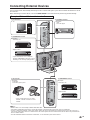
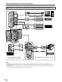
Connecting External Devices........................................ 43
Example of External Devices that can be
Connected .......................................................... 43
Connecting a VCR, DVD Player or a Camcorder
to COMPONENT1/COMPONENT2/AV1/AV-IN2/PC-IN ...
44
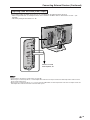
Outputting Video and Audio (Video Output) ............. 45
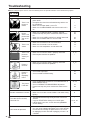
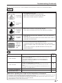
Troubleshooting ............................................................. 46
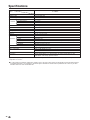
Specifications ................................................................. 48
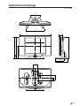
Dimensional Drawings................................................... 49
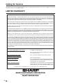
Calling for Service.......................................................... 50
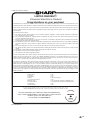
LIMITED WARRANTY ..................................................... 50

7
LIQUID CRYSTAL TELEVISION
TÉLÉVISEUR ACL
TELEVISOR CON PANTALLA DE
CRISTAL LÍQUIDO
TELEVISOR DE CRISTAL
LÍQUIDO
LC-20B6U
OPERATION MANUAL
MODE D’EMPLOI
MANUAL DE OPERACIÓN
MANUAL DE OPERAÇÃO
Products that have earned the ENERGY STAR
®
are designed to protect the environment
through superior energy efficiency.
ENGLISHFRANÇAISESPAÑOLPORTUGUÊS
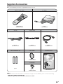
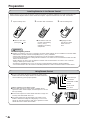
Make sure the following accessories are provided with the LCD TV set.
Supplied Accessories
Operation manual
Wireless remote control
“AAA” size batteries (×2)
AC adapter
pages 8 and 13
RRMCGA293WJSA
page 8
page 10
UADP-A065WJPZ
Antenna cable
page 9
QCNWG0003CEPA
RGB cable
Cable holder
page 12
LHLDWA037WJSA
TINS-B253WJZZ
AC cord
page 40
QCNWGA050WJPZ
page 10
QACCDA037WJPA
A
• The AC cord enclosed in this product is for 110-125V. In using it on the 125-240V AC, please consult to the following.
SHARP ELECTRONICS CORPORATION
6100 Blue Lagoon Drive, Suite 230, Miami, Florida 33126, U.S.A.
Cable clamp
page 12
LHLDWA002WJSA

8
Installing Batteries in the Remote Control
Before using the LCD TV set for the first time, install the two “AAA” size batteries supplied in the remote control. When the
batteries become depleted and the remote control fails to operate, replace the batteries with new “AAA” size batteries.
1 Open the battery cover. 2 Insert two “AAA” size batteries. 3 Close the battery cover.
■ Place batteries with their
terminals corresponding
to the (+) and (–)
indications in the battery
compartment.
Caution!
Precautions regarding batteries
■ Improper use of batteries can result in a leakage of chemicals and/or explosion. Be sure to follow the instructions below.
• Place batteries with their terminals corresponding to the (+) and (–) indications.
• Different types of batteries have different characteristics. Do not mix batteries of different types.
• Do not mix old and new batteries. Mixing old and new batteries can shorten the life of new batteries and/or cause old
batteries to leak chemicals.
• Remove batteries as soon as they are depleted. Chemicals that leak from batteries can cause a rash. If chemical
leakage is found, wipe it off with a cloth.
• The batteries supplied with the LCD TV set may have a shorter operating time due to storage conditions.
• If the remote control is not to be used for an extended period of time, remove the batteries from the remote control.
Preparation
■ Engaging the lower
claw with the remote
control, close the
cover.
Using Remote Control
■ Use the remote control by pointing it towards the remote sensor
window of the main unit. Objects between the remote control and
sensor window may prevent proper operation.
Cautions regarding use of remote control
■ Do not apply shock to the remote control. In addition, do not
expose the remote control to liquids, and do not place it in an area
with high humidity.
■ Do not install or place the remote control under direct sunlight. The
heat may cause deformation of the unit.
■ The remote control may not work properly if the remote sensor
window is under direct sunlight or strong lighting. In such a case,
change the angle of the lighting or main unit, or operate the remote
control closer to the remote sensor window.
■ Slide the cover while
pressing the (
) part.
+
–
+
–
HEADPHONE jack
OPC indicator
POWER/WAKE UP TIMER
indicator
Remote sensor
OPC sensor

9
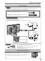
Preparation (Continued)
Antenna Connection
OUTDOOR ANTENNA CONNECTION
• Use one of the following two diagrams if you connect an outdoor antenna.
A: Using a VHF/UHF combination outdoor antenna
B: Using separate VHF and/or UHF outdoor antennas
• Connect the outdoor antenna cable lead-in to ANT. (Antenna terminal) on the rear of the main unit.
1. A 75-ohm system is generally a round cable with F-type connector that can easily
be attached to a terminal without tools (not supplied).
2. A 300-ohm system is a flat “twin-lead” cable that can be attached to a 75-ohm
terminal through a 300/75-ohm adapter (not supplied).
• The antenna requirements for good color television reception are more important than those for black & white television
reception. For this reason, a good quality outdoor antenna is strongly recommended.
The following is a brief explanation of the type of connections that are provided with the various antenna systems.
ANTENNAS
75-ohm
coaxial cable
300-ohm
twin-lead
VHF/UHF
antenna
VHF/UHF
antenna
300/75-ohm
adapter
(not supplied)
300-ohm
twin-lead
300-ohm
twin-lead
75-ohm
coaxial cable
OUT IN
VHF
antenna
UHF
antenna
Combiner
(not supplied)
or
or
A. Combination VHF/UHF Antenna
B. Separate VHF and/or
UHF Antennas
ANT. (Antenna terminal)
Antenna cable (supplied)
F-type connector
75-ohm coaxial cable
When connecting the RF cable to the LCD TV set, do not tighten F-type
connector with tools.
If tools are used, it may cause damage to your LCD TV set.
(The breaking of internal circuit, etc.)
F-type connector should be finger-tightened only.
NOTICE
F-type connector
75-ohm coaxial cable (round)
300-ohm twin-lead cable (flat)
Removing the Terminal Cover
■ Before connecting cables and cords to the rear terminals, remove the terminal covers. Push
in the tabs and pull out the terminal covers carefully.
■ To mount the cover, insert the 2 hooks on the bottom of the cover into the cabinet and press
on the upper part of the terminal cover until the tab locks in place with a click.

10
Preparation (Continued)
A
• Consult your SHARP Dealer or Service Center for the type of splitter, RF switch or combiner that might be required.
Antenna Connection (Continued)
Cable TV converter/
descrambler
(not supplied)
Two-set
signal
splitter
(not
supplied)
Cable TV Line
RF switch (not supplied)
OUT
• A 75-ohm coaxial cable connector is built into the set for easy hookup. When connecting the 75-ohm coaxial cable
to the set, screw the 75-ohm cable to the ANT. terminal.
• Some cable TV companies offer “premium pay channels”. Since the signals of these premium pay channels are
scrambled, a cable TV converter/descrambler is generally provided to the subscriber by the cable TV company.
This converter/descrambler is necessary for normal viewing of the scrambled channels. (Set your TV to channel 3
or 4, typically one of these channels is used. If this is unknown, consult your cable TV company.) For more
specific instructions on installing cable TV, consult your cable TV company. One possible method of utilizing the
converter/descrambler provided by your cable TV company is explained below.
Please note: An RF switch provided with two inputs (A and B) is required (not supplied).
“A” position on the RF switch (not supplied): You can view all unscrambled channels by using the TV’s channel keys.
“B” position on the RF switch (not supplied): You can view the scrambled channels via the converter/descrambler by
using the converter’s channel keys.
CABLE TV (CATV) CONNECTION
■ Using the AC Adapter
• Although the AC adapter may become warm during use, this is not a malfunction.
• Do not wrap or cover the AC adapter with a blanket or similar covering. This can cause a malfunction or accident.
• Do not attempt to disassemble or modify the AC adapter. The insides of the AC adapter contain high-voltage components
that can result in the risk of electrical shock.
A
• Use a commercially available AC plug adapter, if necessary, depending on the design of the wall outlet.
• Always turn the MAIN POWER switch of the main unit to off when connecting the AC adapter.
• Unplug the AC adapter from the product and power outlet when not using for a long period of time.
Power Connection
Household power outlet
AC adapter
POWER INPUT
terminal (DC 12V)
MAIN POWER
AC cord
IN

11
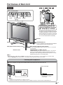
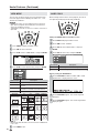
Part Names of Main Unit
Controls
A
• INPUT, CH (
)/( ), VOL (–)/(+) and MENU on the main unit have the same functions as the same buttons on the remote control.
Fundamentally, this operation manual provides a description based on operation using the remote control.
HEADPHONE jack
Plug the headphone mini-plug into the Headphone
jack located on the front of the main unit.
OPC (Optical Picture Control) sensor
Remote sensor
OPC indicator (Optical Picture Control)
The OPC indicator lights up green when the “OPC” is set to “ON”.
(See page 22.)
POWER/WAKE UP TIMER indicator
POWER indicator lights up green when the power is on, and red
when in the standby mode (the indicator will not light when the
main power is off), and orange when the wake-up timer is set (the
indicator will light when in the standby mode).
To change the vertical angle of the LCD TV
set, tilt the screen up to 5 degrees forward or
10 degrees backward. The LCD TV set can
also be rotated up to 25 degrees to right and
left. Please adjust the angle so that the LCD
TV set can be watched most comfortably.
MAIN POWER
Upper control panel
INPUT
MENU
CH (Channel)
(
)/( )
VOL (Volume)
(–)/(+)
Speaker
Speaker
Listening with Headphones
■ Plug the headphone mini-plug into the HEADPHONE jack located on the front of the main unit.
A
• Headphones are not included in the supplied accessories.
• No sound is heard from the main unit speakers when a headphone mini-plug is connected into the HEADPHONE jack.
▼ On-screen display
20
VOLUME
Adjust the sound volume
using VOL (
+)/(–) on the
remote control.
Headphones

12
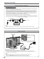
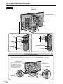
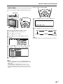
Part Names of Main Unit (Continued)
Terminals
Carrying handle
Rear View
Y
P
B
P
R
AUDIO (L)
AUDIO (R)
VIDEO
AUDIO (R)
AUDIO (L)
AV-IN2/OUT
ANT. (Antenna terminal)
POWER INPUT
(DC 12V)
P
R
P
B
Y/VIDEO
AUDIO (L)
AUDIO (R)
S-VIDEO
COMPONENT2/AV1
COMPONENT1
ANALOG RGB
AUDIO
PC-IN
How to Fix the Cables
• Pull the cables connected to each terminal through the holes and close the left and right terminal covers.
Push the cables into the grooves of the support cover. Insert the cable holder (supplied) from above the
support cover and fix the cables.
Terminal cover
Cable holder
Terminal cover
Support cover
Cable clamp
When the cables cannot be
pushed into the grooves of
the support cover, use the
cable clamp (supplied) to fix
them. The cable clamp can
be attached by pushing it
into the hole on the stand.

13
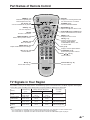
Part Names of Remote Control
DISPLAY
Displays the receiving channel and
the current time for 10 seconds.
AV MODE (p. 21)
Selects preferred AV MODE.
BACKLIGHT (p. 22)
Adjusts the brightness of the screen.
' / " / \ / | (Cursor control) (p. 19)
Selects a desired item on the screen.
MENU (p. 19)
Displays the menu screen.
INPUT (p. 17)
Switches the input source
between COMPONENT1,
COMPONENT2 (or AV1), AV2,
PC and TV mode.
CC (p. 35)
Displays Closed Caption subtitles.
FLASHBACK (p. 18)
Returns to the previous channel.
CH (
)/( ) (p. 18)
Selects channel.
Channel Select (p. 18)
Sets the channel.
POWER (p. 17)
Switches the Liquid Crystal
Television power on or off.
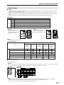
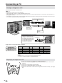
TV Signals in Your Region
This product is factory set to comply with the TV broadcasting system in the United States. For Brazil, Argentina and Uruguay,
set the color system according to the country before using this product by following the table below.
U.S.A.
Color: NTSC NTSC (N358) NTSC (N358)
TV ch: US ch US ch US ch
Not required or N/A
Canada, Mexico, Color: NTSC NTSC (N358) NTSC (N358)
Latin America TV ch: US ch US ch US ch
Not required or N/A
Brazil
Color: PAL-M NTSC (N358) NTSC (N358) Set color system to
TV ch: US ch US ch US ch PAL-M (see page 28)
Argentina, Color: PAL-N NTSC (N358) NTSC (N358) Set color system to
Uruguay TV ch: US ch US ch US ch PAL-N (see page 28)
A
• The 3 Dimensional Y/C separation circuit* only works when the color system is set to N358 in TV mode and Video mode.
* The 3 Dimensional Y/C separation circuit is used to remove flickering and color bleeding.
* The 3 Dimensional Y/C separation circuit does not function when S-VIDEO or COMPONENT signals are played.
TV broadcasting
system
Factory setting of color system User setting
TV Video TV/Video
Country
PIC. FLIP (p. 39)
Sets the orientation of the picture.
SLEEP (p. 37)
Sets the sleep timer.
ENTER
Executes a command.
MENU RETURN (p. 19)
Returns to the previous screen.
MUTE (p. 18)
Mutes the sound.
AUDIO ONLY (p. 36)
Outputs audio without screen image.
VOL (+)/(–) (p. 18)
Sets the volume.
MTS (p. 18)
Selects audio settings.

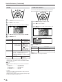
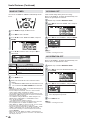
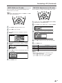
14
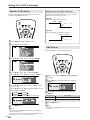
Press MAIN POWER, located on the upper side of the
main unit, to turn on the TV. The SELECT LANGUAGE
mode will be displayed.
Press '/" to select “ENGLISH”, “ESPAÑOL”
(Spanish) or “FRANÇAIS” (French).
MENU
MENU
[
SETUP
…
C H – S E T T I N G ]
E Z S E T U P
S E L E C T L A N G U A G E
E N G L I S H
E S P A Ñ O L
F R A N Ç A I S
Press ENTER to access CH-SETTING mode.
Press '/" to select “ON” or “OFF”. When you select
“ON”, the LCD TV set will automatically memorize the
broadcasting channels.
C H – S E T T I N G
O N
O F F
MENU
MENU
[
SETUP
…
C H – S E T T I N G ]
E Z S E T U P
A
• If you select “OFF” in “EZ SETUP, CH-SETTING”, EZ SETUP will
be canceled.
Press ENTER to access AUTO CLOCK mode.
Press '/" to select “ON” or “OFF”.
When you select “ON”, the LCD TV set will
automatically adjust the clock to search time-signals
(EDS signals), which are provided by some TV stations.
The AUTO CLOCK setting may take from several
minutes to an hour depending on the number of
channels to receive and signal status. If you know the
channel of the EDS signal carrier (PBS or other) in your
area, select “OFF” and follow the procedure in AUTO
CLOCK Setting. (See page 15.)
A U T O C L O C K
O N
O F F
MENU
MENU
[
SETUP
…
C H – S E T T I N G ]
E Z S E T U P
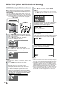
■ When you turn on the TV for the first time, it will automati-
cally memorize the broadcasting channels and clock.
Please perform the following instructions before you press
MAIN POWER.
(1)
Insert the batteries into the remote control. (See page 8.)
(2)
Connect the antenna cable to the LCD TV set. (See page 9.)
(3)
Connect the AC adapter to the POWER INPUT terminal of the LCD
TV set and plug in the AC cord to the wall outlet. (See page 10.)
EZ SETUP (With AUTO CLOCK Setting)
EZ SETUP during the First Power On
MAIN POWER
1
2
3
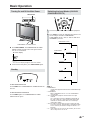
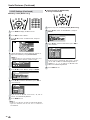
Press ENTER to access START EZ SETUP mode.
Press '/" to select “YES”, and press ENTER.
A
•
If you want to stop the EZ SETUP process once it has started,
press MENU and it will be canceled. If you want to set up again,
please refer to pages 26 and 27 on CH-SETTING.
S T A R T E Z S E T U P ?
Y E S
N O
C O N N E C T A N T E N N A
O R C A B L E .
MENU
MENU
[
SETUP
…
C H – S E T T I N G ]
E Z S E T U P
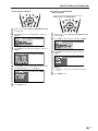
The tuner will automatically search for the broadcasting
and cable TV channels. (The channel number will
automatically increase when it appears.)
P L E A S E W A I T
A U T O P R O G R A M M I N G
The LCD TV set will automatically switch to searching
for EDS signals.
If EDS signals are received, the channel number and time will
be displayed, and then the screen shown in step 5 appears.
P L E A S E W A I T
N O W S E A R C H I N G T I M E
Once EZ SETUP is completed, the lowest channel
number memorized will be displayed.
S T E R E O
S A P
M O N O 1 1 : 5 3 A M
2
A
• Do not let the EZ SETUP screen remain unattended for a long time.
• If EZ SETUP does not memorize all the channels in your region,
please refer to pages 26 and 27 for more information on manually
memorizing the channels using CH-SETTING.
•
It may be difficult to preset when the broadcasting signals are weak,
the channel cycle frequency is incorrect or the frequency jamming is
occurring around the area. Please refer to pages 26 and 27 for more
information on manually memorizing channels using CH-SETTING.
•
If there are no channels with EDS signals or the antenna signal is weak,
the AUTO CLOCK setting may not operate. In this case, a “EDS CH IS
NOT AVAILABLE.” message will appear and the mode will change to
MANUAL CLOCK setting. Refer to page 16 to set the clock manually.
4
5

15
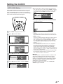
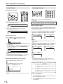
Setting the CLOCK
AUTO CLOCK Setting
There are two methods of setting the clock: AUTO CLOCK
and MANUAL CLOCK. AUTO CLOCK uses EDS signals,
which are provided by some TV stations, to automatically
adjust the clock. MANUAL CLOCK sets the clock manually in
areas where no channel carries EDS signals.
Press MENU to display the Menu screen.
Press c/d to select “SETUP”.
MENU[
MENU[
SETUP
SETUP
]
PICTURE
PICTURE
AUDIO
SETUP
SETUP
OPTION
OPTION
C H – S E T T I N G
M T S
C L O C K
C O M P . 2 / A V 1 S E L E C T
A V 2 I N / O U T
V – C H I P B L O C K
C L O S E D C A P T I O N
C O L O R S Y S T E M
P C S E T T I N G
L A N G U A G E
Press '/" to select “CLOCK”, and press ENTER.
MENU
MENU
[
SETUP
SETUP
…
C L O C K ]
PICTURE
PICTURE
AUDIO
SETUP
SETUP
OPTION
OPTION
C H – S E T T I N G
M T S
C L O C K
C O M P . 2 / A V 1 S E L E C T
A V 2 I N / O U T
V – C H I P B L O C K
C L O S E D C A P T I O N
C O L O R S Y S T E M
P C S E T T I N G
L A N G U A G E
Press '/" to select “SET”, and press ENTER.
MENU
MENU
[
SETUP
SETUP
…
C L O C K ]
S E L E C T O P T I O N
S E T
T I M E D I S P L A Y A U T O
M A N U A L
Press '/" to select “AUTO”, and press ENTER.
MENU
MENU
[
SETUP
SETUP
…
C L O C K ]
S E L E C T O P T I O N
S E T
T I M E D I S P L A Y A U T O
M A N U A L
● If you do not know the channel that carries EDS signals in your
area, select “EDS CH” to “AUTO” and press ENTER. If you know
the channel of the EDS signal carrier in your area, press c/d to
select channel and press ENTER. Set the EDS CH and press
ENTER.
MENU
MENU
[
SETUP
…
C L O C K ]
A U T O C L O C K
S E T
T I M E D I S P L A Y E D S C H A U T O
● When set to “AUTO CLOCK”, the time is acquired automatically
when MAIN POWER is turned OFF. (This function will not work
when EDS CH is not set.)
S T E R E O
S A P
M O N O 1 1 : 5 3 A M
2
A
• CLOCK:
The AUTO CLOCK setting may take from several minutes to an
hour depending on the number of channels to receive and signal
status.
• EDS CH < AUTO >:
If there are no channels with EDS signals or the antenna signal is
weak, the AUTO CLOCK Setting may not operate. In such a
case, the message “EDS CH IS NOT AVAILABLE.” appears, and
the CLOCK setting screen (in step 4 in this page) is displayed.
Refer to MANUAL CLOCK Setting on page 16 to set the clock
manually.
• EDS CH < Not AUTO >:
If the channel you have selected for “EDS CH” is wrong or the
EDS signal carrier is weak, or when there is no broadcast, the
AUTO CLOCK Setting may not operate. In such cases, the
message “EDS CH (XXX) EDS DATA IS NOT AVAILABLE.”
appears, and the CLOCK setting screen (in step 4) is displayed as
in the case with EDS CH < AUTO >. Follow step 4 and repeat the
AUTO CLOCK Setting procedure.
• If broadcasting channels are not memorized, EDS signals cannot
be received even when the “EDS CH” is set to “AUTO”. In this
case, try EZ SETUP again. (See page 26.)
■ Backup
The clock function is maintained for about 10 minutes even
when the AC adapter has been shut off due to a power
outage or when moving the LCD TV set. (Since about 30
minutes are required to charge the backup power supply, it
may not be possible to maintain the clock function if the
charging time is excessively short.)
If the clock setting has been reset, refer to Setting the
CLOCK on pages 15 and 16.
2
1
3
4
5

16
Setting the CLOCK (Continued)
TIME DISPLAY
You can display the current time on the screen.
Repeat steps 1 to 3 of MANUAL CLOCK Setting on
this page.
Press '/" to select “TIME DISPLAY”, and press
ENTER.
MENU
MENU
[
SETUP
…
C L O C K ]
S E L E C T O P T I O N
S E T
T I M E D I S P L A Y O N
O F F
Press '/" to select “ON” or “OFF”, and press
ENTER.
Press MENU to exit.
A
• When you press DISPLAY, the current time is displayed for about
10 seconds.
Selected item Description
ON Displays the current time on the screen.
OFF No display
1
MANUAL CLOCK Setting
If there are no channels with EDS signals, set the clock
manually using MANUAL CLOCK.
Press MENU to display the Menu screen.
Press c/d to select “SETUP”.
MENU[
MENU[
SETUP
]
PICTURE
AUDIO
SETUP
OPTION
C H – S E T T I N G
M T S
C L O C K
C O M P . 2 / A V 1 S E L E C T
A V 2 I N / O U T
V – C H I P B L O C K
C L O S E D C A P T I O N
C O L O R S Y S T E M
P C S E T T I N G
L A N G U A G E
Press '/" to select “CLOCK”, and press ENTER.
MENU[
MENU[
SETUP
…
C L O C K ]
PICTURE
AUDIO
SETUP
OPTION
C H – S E T T I N G
M T S
C L O C K
C O M P . 2 / A V 1 S E L E C T
A V 2 I N / O U T
V – C H I P B L O C K
C L O S E D C A P T I O N
C O L O R S Y S T E M
P C S E T T I N G
L A N G U A G E
Press '/" to select “SET”, and press ENTER.
Press '/" to select “MANUAL”, and press ENTER.
MENU
MENU
[
SETUP
…
C L O C K ]
S E L E C T O P T I O N
S E T
T I M E D I S P L A Y A U T O
M A N U A L
Press '/" to select “DST”, and press c/d to select
“ON” or “OFF”.
Press '/" to select “TIME”, and press c/d to set the
time, and press ENTER.
12:00AM 11:59AM
11:59PM 12:00PM
• Holding down c/d changes the setting at a high speed.
MENU
MENU
[
SETUP
…
C L O C K ]
M A N U A L C L O C K
S E T
T I M E D I S P L A Y D S T O F F
T I M E 1 2 : A M
00
Press MENU to exit.
A
• Make sure to press ENTER after adjusting the time. Otherwise,
the time will not be set.
• When DST is set to “ON”, the time entered is forwarded by 1 hour.
• Please be sure to set “DST” before setting “TIME”.
2
3
Daylight Saving Time (DST) Adjustment
The Daylight Saving-Time changes as shown below, set the
DST to “ON” to forward the clock by 1 hour. To rewind the
clock by 1 hour, set the DST to “OFF”.
(Spring)
On the first Sunday in April DST starts.
(Autumn)
On the last Sunday in October DST finishes.
1:00AM 2:00AM
3:00AM 4:00AM
Advances 1 hour.
1:00AM 2:00AM
1:00AM 2:00AM
Rewinds 1 hour.
1
4
5
6
2
3
4

17
Turning On and Off the Main Power
● Press MAIN POWER. The POWER/WAKE UP TIMER
indicator instantly changes from red to green and the
LCD TV set is turned on.
A
• The On-screen display disappears after a few seconds.
● To turn off the main power, press MAIN POWER again.
Standby
To turn off the LCD TV set
Press POWER. The POWER/WAKE UP TIMER indicator will
turn red.
To turn the LCD TV set back on
Press POWER again. The POWER/WAKE UP TIMER
indicator will turn green.
POWER/WAKE UP TIMER indicator
MAIN POWER
Basic Operation
S T E R E O
S A P
MONO
MONO 11:53AM
On-screen display
Switching the Input Modes (AV1/AV2/
COMPONENT/PC/TV)
Turn on the power of the connected video equipment.
Press INPUT to select the applicable input source. The
screen changes in order of COMPONENT1,
COMPONENT2 or AV1, AV2, PC and TV mode each
time INPUT is pressed.
A
• COMPONENT1:
Used for video equipment connected to the COMPONENT input
terminals.
• COMPONENT2:
When COMPONENT2 or AV1 is set as COMPONENT2.
(See page 28.)
• AV1: Used for video equipment connected to the AV1 input
terminals.
The S-video input terminal is additionally provided for the
AV1 input. If both the S-video terminal and normal video
terminals are connected with cables, the S-video input
terminal takes priority.
• AV2: AV2 mode is used to adjust the preset settings and IN or
OUT can be selected. AV2 indication is not displayed when
OUT is selected. (For details on setting AV2 IN/OUT, see
page 28.)
• PC: If you connect the PC to the PC-IN terminals, you can view
the PC image on the LCD TV set.
1
2
AV2 mode
AV1
AV2
PC
or
CONPONENT1
COMPONENT1 mode
CONPONENT2
COMPONENT2
mode
AV1 mode
PC mode
TV mode
2
480P
480P

18
Basic Operation (Continued)
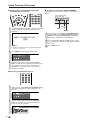
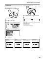
Changing Channels
You can select channels using Channel Select or
CH (
)/( ).
• This LCD TV set allows you to select up to 125 channels
(1 to 125). To select a channel, enter a 2- or 3-digit number.
■
Using Channel Select
When selecting the channel using Channel Select, complete
input of the channel number by holding down the button for
the last digit for a moment.
To select a 1- or 2-digit channel number (e.g., Channel 5):
Complete the following procedure within 4 seconds.
Press the button. Press the button.
0–
5
A
• When selecting a 1-digit channel number, do not fail to press the
button first.
To select a 3-digit channel number (e.g., Channel 115):
Complete the following procedure within 4 seconds.
Press the button. Press the button.
1––
11–
Press the button.
115
A
• The 3-digit channel number can be selected only when the
receiving mode is set to CABLE in CH-SETTING. (For details on
setting the receiving mode, see page 26.)
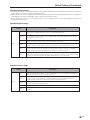
Changing channels with CH ( )/( ) on the remote control
Air:
Press CH ( ) and the channels change in the order shown below:
2 A 3 A . . . A 68 A 69 A 2 A 3 A . . .
Press CH ( ) and the channels change in the order shown below:
3 A 2 A 69 A 68 A . . . A 3 A 2 A . . .
Cable: Press CH ( ) and the channels change in the order shown below:
1 A 2 A 3 A . . . A 125 A1 A 2 A 3 A . . .
Press CH ( ) and the channels change in the order shown below:
3 A 2 A 1 A 125 A . . . A 3 A 2 A 1 A . . .
■ Using FLASHBACK
● Press FLASHBACK to switch the currently tuned channel
to the previously tuned channel.
● Press FLASHBACK again to switch back to the currently
tuned channel.
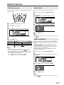
Sound Volume
■ To adjust the volume
● Press VOL (+) to increase the sound volume.
The bar indicator shifts right.
VOLUME
50
● Press VOL (–) to decrease the sound volume.
The bar indicator shifts left.
VOLUME
10
■ To mute the sound
● Press MUTE to temporarily turn off the sound.
The MUTE mark
is displayed for 4 seconds.
● Press MUTE or VOL (+)/(–) to turn the sound back to the
previous level.
The mute function is automatically turned off when any of
the following buttons are pressed: POWER, MUTE,
VOL (+)/(–) or MTS.
VOLUME
10
A
• When VOL (+)/(–) is pressed in the Mute mode, the sound turns
on and the volume indicator is displayed.
• The Mute function is cancelled when POWER is pressed.
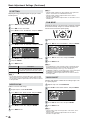
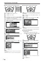
■ To select MTS (Multichannel TV Sound)
Press MTS to display the MTS screen.
Press MTS to select the MTS settings.
STEREO: stereo audio
SAP: secondary audio program
MONO: monophonic audio
STEREO
<
ON A I R
<
ON A I R
SAP
M
ONO
A
• “ON AIR” appears when a STEREO or SAP broadcast is being
aired.
1
2
1
3
1 2
2

19
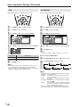
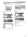
Basic Operation (Continued)
■ Using direct control menu
Press MENU on the main unit to display the Menu
Screen.
Press VOL (–)/(+) to select the desired menu item.
• The cursor moves left or right.
• The cursor indicates the selected menu item.
Press CH (
)/( ) to select the desired item and press
VOL (–)/(+) to adjust the selected item.
• For “AV MODE”, “OPC”, “ADVANCED” and “RESET”,
press INPUT to display the setting screen.
MENU[
MENU[
PICTURE
]
PICTURE
S
AUDIO
SETUP
OPTION
A V M O D E [ D Y N A M I C ]
O P C [ O F F ]
B A C K L I G H T [
BRIGHT
]
C O N T R A S T [ 5 6 ]
B R I G H T N E S S [ ] – +
C O L O R [ + 2 ] – +
TINT [
TINT [
]
S H A R P N E S S [ + 4 ] – +
A D V A N C E D
R E S E T
0
0
Press MENU to return to the previous screen.
• Each time MENU is pressed, you will return to the
screen previously shown.
Control panel of the main unit
CH ( )/( )
(Channel)
VOL (–)/(+)
(Volume )
MENU
INPUT
1
4
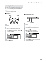
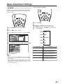
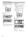
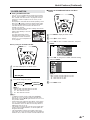
Selecting Menu Items
The menus can be used to adjust the various settings of your
LCD TV set. Select the desired menu item by following the
steps below. See the next page for each Menu screen.
A
• The items displayed differ depending on the setting conditions.
• The item selected is displayed in yellow.
• Settings most recently adjusted will be saved in memory.
■ Using menus
Press MENU on the remote control to display the Menu
Screen.
Press \/| to select the desired menu item.
• The cursor moves left or right.
• The cursor indicates the selected menu item.
Press '/" to select the desired item, and press \/|
to adjust the selected item.
• For “AV MODE”, “OPC”, “ADVANCED” and “RESET”,
press ENTER to display the setting screen.
MENU[
MENU[
PICTURE
PICTURE
]
PICTURE
PICTURE
S
AUDIO
AUDIO
SETUP
SETUP
OPTION
OPTION
A V M O D E [ D Y N A M I C ]
O P C [ O F F ]
B A C K L I G H T [
BRIGHT
]
C O N T R A S T [ 5 6 ]
B R I G H T N E S S [ ] – +
C O L O R [ + 2 ] – +
TINT [
TINT [
]
S H A R P N E S S [ + 4 ] – +
A D V A N C E D
R E S E T
0
0
Press MENU RETURN to return to the previous screen,
or press MENU to exit.
1
2
3
4
2
3
Page is loading ...
Page is loading ...
Page is loading ...
Page is loading ...
Page is loading ...
Page is loading ...
Page is loading ...
Page is loading ...
Page is loading ...
Page is loading ...
Page is loading ...
Page is loading ...
Page is loading ...
Page is loading ...
Page is loading ...
Page is loading ...
Page is loading ...
Page is loading ...
Page is loading ...
Page is loading ...
Page is loading ...
Page is loading ...
Page is loading ...
Page is loading ...
Page is loading ...
Page is loading ...
Page is loading ...
Page is loading ...
Page is loading ...
Page is loading ...
Page is loading ...
Page is loading ...
Page is loading ...
-
 1
1
-
 2
2
-
 3
3
-
 4
4
-
 5
5
-
 6
6
-
 7
7
-
 8
8
-
 9
9
-
 10
10
-
 11
11
-
 12
12
-
 13
13
-
 14
14
-
 15
15
-
 16
16
-
 17
17
-
 18
18
-
 19
19
-
 20
20
-
 21
21
-
 22
22
-
 23
23
-
 24
24
-
 25
25
-
 26
26
-
 27
27
-
 28
28
-
 29
29
-
 30
30
-
 31
31
-
 32
32
-
 33
33
-
 34
34
-
 35
35
-
 36
36
-
 37
37
-
 38
38
-
 39
39
-
 40
40
-
 41
41
-
 42
42
-
 43
43
-
 44
44
-
 45
45
-
 46
46
-
 47
47
-
 48
48
-
 49
49
-
 50
50
-
 51
51
-
 52
52
-
 53
53


Ask a question and I''ll find the answer in the document
Finding information in a document is now easier with AI
Related papers
Other documents
-
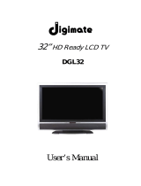
Dynex DX-R20TV User manual
-
-
 PYLE Audio PLVWR750T User manual
-
LG LAM770T1 Owner's manual
-
Sanyo ST-21YS2BS Owner's manual
-
Kenwood KVX-5 User manual
-
Audiovox Flat Panel Television FP1500 User manual
-
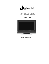
 Digimate DGL32 User manual
-
 Digimate DGL2700 User manual
-
Clover Electronics TFT7001 User manual


