Craftsman 917.271080 Owner's manual
- Category
- Lawnmowers
- Type
- Owner's manual
This manual is also suitable for

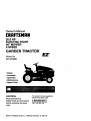
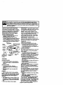
Owner's Manual
CRAFTSMAN
20.0 HP
ELECTRIC START
46" MOWER
6 SPEED
GARDEN TRAC
Model No.
917.273031
• Safety
• Assembly
• Operation
• Maintenance
• Repair Parts
CAUTION:
Read and follow all
Safety Rules and Instructions
before operating this equip-
ment.
For answers to your questions
about this product, Call:
1-800-659-5917
Sears Craftsman Help Une
5 am. 5pm,Mort- Sat
Seam, Roebuck and Co., Hoffman Estates, IL 60179

Warranty ,,,,,..,,.,,,,,o,.,,,,,.o, ........... ._oo.,oo....2
Safety Rules ........................................... 2
- _embly .............................. 8
OpereUon, .._-_...:.:::.:.._............................. 12
Maintenance Schedule ......................... lg
M_ntanance.........................................19
ServiceandAdjustments......................23
Storage.................................................31
Troubleshooting....................................32
Repair Parts.........................................36
PartsOrdering.......................BackCover
LIMITED TWO YEAR WARRANTY ON CRAFTSMAN RIDING EQUIPMENT
For two (2) years from the date of purchase, ifthis Craftsman Riding Equipment is main-
tained, lubricated and tuned up according to the instructions in the owner's manual,
Sears will repair or replace, free of charge, any parts found to be defective in material or
workmanship.
This Warranty does not cover:.
• Expendable items which become wom during normal usa, such as blades, spark
plugs, air cleaners, belts, etc.
• Tire replacement or repair caused by punctures from outside objects, such as nails,
thorns, stumps, or glass.
• Repairs necessary because of operator abuse, negligence, improper storage or acci-
dent or the failure to maintain the equipment according to the instructions contained in
the owner's manual.
• Riding equipment used for commercial or rental purposes.
LIMITED 90 DAY WARRANTY ON BA]-I'ERY
For ninety (90) days from date of purchase, if any battery included with this riding equip-
ment proves defective in material or workmanship and our testing determines the bat-
tery will not hold a charge, Sears will replace the battery at no charge. In-home warranty
service on your Craftsman riding equipment isavailable at no charge for 30 days from
the date of pumhasa. Please contact your nearest service center. After 30 days from the
date of purchase, warranty service is available by taking your Craftsman riding equip-
ment to your nearest Sears Service Center. (In-home warranty service will still be avail-
able after 30 days from the date of purchase but a standard trip charge will apply). This
warranty applies only while this product is in the United States. This Warranty gives you
specific legal rights, and you may also have other rights which may vary from state to
state.
Sears, Roebuck and Co., D/817 WA, Hoffman Estates, IL 60179
GENERAL OPERATION
• Read, understand, and follow all instruc-
tions in the manual and on the machine
before starting.
• Only allow responsible adults, who are
familiar with the instructions, to operate
the machine.
• Clear the area of objects such as rocks,
toys, wire, etc., which could be picked
up and thrown by the b/ade.
• Be sure the area is clear of other people
befef_ mowing. Stop machine it anyone
enters the area.
• Nevercarrypassengers.
• Do notmowinreverseunlessabsolute-
lynecessary.Alwayslookdownand
behindbeforeandwhilebacking.
• Beaware ofthemowerdischargedirec-
tionanddonotpointitat anyone.Do
notoperatethe mowerwithouteither
theentiregrasscatcherortheguardin
place.
• Slowdownbefore turning.
• Neverleavea runningmachineunat-
tended.Alwaysturnoffblades,setpark-
ingbroke,stopengine,andremove
keysbeforedismounting.
2

• Turn off blades when not mowing.
• Stop engine before removing grass
catcher or unclogging chute.
• Mow only in daylight or good artificial
light.
• Do not operate the machine while under
the influence of alcohol or drugs.
o-Watch for traffic when operating near or
crossing roadways.
• Use extra care when loading or unload-
ing the machine into a trailer or track.
SLOPE OPERATION
Slopes are a major factor related to loss-
of-control and tipover accidents, which
can result in severe injury or death. All
slopes require extra caution. If you cannot
back up the slope or if you feel uneasy on
it, do not mow it.
DO:
• Mow up and down slopes, not across.
• Remove obstacles such as rocks, tree
limbs, etc.
• Watch for holes, ruts, or bumps. Uneven
terrain could overturn the machine. Tall
gross can hide obstacles.
• Use slow speed. Choose a low gear so
that you will not have to stop or shift
while on the slope.
• Follow the manufacturer's recommen-
datioos for wheel weights or counter-
we_hts to improve stability.
• Use extra care with grass catchers or
other attachments, These can change
the stability of the machine.
• Keep all movement on the slopes slow
and gradual. Do not make sudden
changes in speed or direction.
• Avo'KLstartingor stopping on a slope, if
flms lose traction, disengage the blades
and proceed slowly straight down the
slope.
DO NOT:
• Do nottum on slopes unless necessary,
and then, turn slowly and gradually
downhill, it possible.
• Do not mow near drop-offs, ditches, or
embankments. The mower could sud-
denly tum over if a wheel is over the
edge of a cliff or ditch, or if an edge
caves in.
• Do g_ mow on wet grass. Reduced
traction could cause sliding.
• Do nottrytostabilizethe machine by
pottingyourfootc_ntheground.
• Do notusegrasscatcheronsteep
slopes.
CHILDREN
Tragicaccidentscan occurif theoperator
isnotalertto'thepresenceofchildren.
Childrenare oftenattreotedtothe
machineandthemowingactivity.Never
assumethatchildrenwillremainwhere
you lest sew them.
• Keepchildrenoutofthe mowingarea
and underthewatchfulcare ofanother
responsibleadult.
• Be alertandturnmachine offif children
enterthearea.
• Beforeandwhenbacking,lookbehind
and downforsmallchiktren.
• Nevercarrychildren.They mayfalloff
and beseriouslyinjuredorinterferewith
safe machineoperation.
• Neverallowchildrentooperatethe
machine.
• Useextracarewhenapproachingblind
comers,shrubs,trees, orotherobjects
thatmayobscurevision.
SERVICE
• Useextracarein handlinggasolineand
otherfuels.They areflammableand
vaporsareexplosive.
Useonlyan approvedcontainer.
Never removegascapor addfuel
with theenginerunning.Allowen-
ginetocoolbeforerefueling.Do not
smoke.
Never refuelthemachineindoors.
Neverstorethe machineorfuel
container insidewherethereisan
openflame,suchas a waterheater.
• Nevermn a machineinsidea closed
area.
i sep nutsand bolts,especiallyblade
attachmentbolts,tightand keepequip
mentin goodcondition.
Never tamperwithsafetydevices.
Checktheirproperoperationreguledy.
Keepmachinefreeofgrass,leaves,or
otherdebdsbuild-up.Cleanoilor fuel
spillage.Allowmachinetocoolbefore
storing.
• Stop andinspectthe equipmentifyou
strike an object.Repair,if necessary,
beforerestarting.

• Nevermakea<_ustmentsorrepairswith
theenginerunning.
• Grasscatchercomponentsaresubject
towear,damage,anddeterioration,
whichcould exposemoving portsor
allowobjectstobe thrown.Frequently
checkcomponentsandreplacewith
" manu|acturer'srecommendedpods,
whennecessary.
• Mower blades are sharp and can cut.
Wrap the blade(s) or wear gloves,and
use extra caution when servicing them.
• Check brake operation frequently.
Adjust and service as required.
• Be sure the area is clear ol other people
before mowing, Stop machine if anyone
enters the area.
• Never carry passengers.
• Do not mow in reverse unless absolute-
ly necessary, Always look down and
behind before and while backing.
• Never camj children. They may fall off
and be seriously injured or interfere with
safe machine operation.
• Keep children out of the mowing area
and under the watchful care of another
responsible adult.
• Be aied and turn machine off if chgdren
enter the area.
• Before and when backing, look behind
and down for small children.
_Look for this symbol to point out impor-
tant safety precautions. It means CAU-
TIONfl!'BECOME AWARE!I! YOUR SAFE-
TY IS INVOLVED.
•,CAUTION: In order to prevent acciden-
tal starting when setting up, tranepo_ng,
adjusting or making repairs always discon-
nect spark plug wire and place wire where
if cannot contact spark plug.
• Mow up and down slopes (15° Max), not
acrosS.
• Remove obstacles such as rocks, tree
limbs, etc.
• Watch for holes, ruts, or bumps. Uneven
terrain could overturn the machine. Tall
grass can hide obstacles.
• Use slow speed. Choose a low gear so
that you will not have to stop or shift
while on the slope.
• Avoidstarting or stepping on a slope; If
tires lose traction, disengage the blades
and proceed slowly straight down the
slope.
• Do nottum on slopes unless necessary,
and then, turn slowly and gradually
downhill, if posslbla.
_WARNING: The engineexhaustfrom
this productcontainschemicalsknownto
theStateofCaliforniatocausecancer,
birthdefects,orotherreproductiveharm.
4

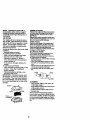
PRODUCT SPECIRGATIONS
GASOLINE 3.5 GALLONS
CAPACITY UNLEADED
_ID TYPE: REGULAR
OILTYPE SAE 30
_.PI-SFiSG/SH): (above 32°F)
SAE 5W-30
(below32°F)
OIL CAPACITY: W/FILTER: 3.5 PINTS
W/O FILTER: 3,0 PINTS
SPARK PLUG: Champion RC12YC
GAP: .030")
VALVE INTAKE:.004"-.006"
;LEARENCE: EXHAUST..004"-.006"
GROUND SPEED LO: HI:
(MPH): 0.7 1.7
1.4 3.3
2.3 5.4
REVERSE: 0.9 2.1
TIRE PRESSURE: FRONT: 14 PSI
REAR: 10 PSI
CHARGING
SYSTEM: 16AMPS @36(30RPM
SATrERY: AMP/FIR: 30
MIN. CCA: 240
CASE SIZE: U1R
BLADE BOLT 27-35 FT. LBS.
TORQUE:
CONGRATULATIONS on your purchase
of a Craftsman Tractor. It has been
designed, engineered and manufactured
to give you the best possible dependability
and performance.
Sbeu.ld_y_ouexperience any problem you
cannot-easily remedy, please contact your
nearest Sears Authodzed Service Center.
We have competent, well-trained techni-
cians and the proper tools to service or
repair this tractor.
Please read and retain this manual. The
instructions will enable you to assemble
and maintain your tractor properly. Always
ol06erve the =SAFETY RULES".
MAINTENANCE AGREEMENT
ASearsMaintenanceAgreementisavail-
able onthis product.Contactyournearest
Sears storefordetails.
CUSTOMER RESPONSIBILITIES
• Read and observe the safety rules.
• Follow a regular schedule in maintain-
ing, caring for and using your tractor.
• Follow the instructions under =Mainte-
nance" and "Storage" sections of this
owner's manual.
_WARNING: This tractor is equipped
with an internal combustion engine and
should not be used on or near any unim-
proved forest-covered, brush-covered or
grass-covered land unless the engine's
exhaust system isequipped with a spark
arrester meeting applicable local or state
laws (if any). If a spark arrester is used, it
should be maintained in effective working
order by the operator.
In the state of California the above is
required by law (Section 4442 of the
California Public Resources Code). Other
states may have similar laws. Federal
laws apply on federal lands. A spark
arrester for the muffler is available through
your nearest Sears Authorized Service
Center (See REPAIR PARTS section of
this manual).

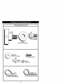
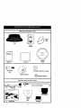
PartsBagcontentsshownfullsize
m
m
/
(I) Knob
©
(1) Washer
17/32 x 1-3/15 x 12 Gauge
(1) Shoulder
Bolt 5/16-18
(2)washers
3/16 x 3/4 x 16 Gauge
(2) Weld
Nuts #10
@
(2)_re_ #10 x 5/8
(2) Lock
Washers #10
(4) Retelner Spdngs (single loop)
(3) Retainer Spdngs (double loop)
6

Partspackedseparatelyincarton
Manual
Seat
I
I
I
I
Video
Cassette
I
I
I
I
I
i
I
i
I
Pads Bag
Mulcher
I Plata
Steering
Wheel
(2) Shoulder
Bolts
(2) Gauge Wheels
©
(2) Washers 3/8x 7/8 x 14 Gauge
Q(2) Canter lockNuts
Parts Bag contents notshown fullsize
_==_ (2) Latch Hook (2) Keys
Assemblies
(2) FrontLink Assemblies
"-J Slage Sheet
Steering _''
Wheel
Insert _rlt_ Sleeve
SteeringSleeve
7

Yournewtractorhasbeenassembledatthefactorywithexceptionofthosepartsleft
unassembledforshippingpurposes.Toensuresafeandproperoperationofyourtractor
allportsandhardwareyouassemblemustbetightenedsecurely.Usethecorrecttools
asnecessarytoinsurepropertightness.Reviewthevideocassettebefore you begin.
TOOLS REQUIRED FOR
ASSEMBLY
"Asocketwrenchset willmake assembly
easier.Standardwrenchsizesyouneed
are listedbelow.
(1) 9/16"wrench (1) 3/4"Socketw/
(1) 1/2"wrench ddve ratchet
(1) Pliers (1) PhillipsScrew-
(1) Utilityknife driver
(1) Tirepressuregauge
When dghtor lefthandismentionedin
thismanual, itmeans,fmmyourpointof
view,when youare inthe operatingposi-
tion (seatedbehindthesteedngwheel).
TO REMOVE TRACTOR FROM
CARTON
UNPACK CARTON
• Remove all accessible loose parts and
parts boxes from shipping carton (See
page 6).
• Cut, from top to bottom, along lines on
all four comers of shipping carton, and
lay panels flat.
• Remove mower and package matedals.
Check for any additional loose parts or
boxes and remove.
BEFORE ROLLING TRACTOR OFF
SKID
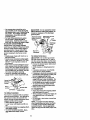
A'I-rACH STEERING WHEEL
• Remove hex bolt, lock washer and large
fiat washer from steedng shaft.
• Position front wheels of the tractor so
they are pointing straight forward.
• Slid'e-_hesteedng sleeve over the steer-
ing shaft.
• Align tabs and press steedhg sleeve
extension intobottom of steedeg wheel.
• Position steedng wheel so cross bars
are horizontal (left to right) and slide
onto steedng wheel adapter.
• Secure steering wheel to steedng shaft
with hex bolt, lock washer and large fiat
washer previously removed. Tighten
securely, o
• Snap steedng wheel insert into canter
of steedng wheel.
• Remove protective materials from trac-
tor hood and gdlL
_--_ tssdng
Wheel Insert
_[.._ Hex Bolt
_._ LockWasher
LargeRat
Washer
Steedng
Steedng Wheel
Wheel Adapter
Extension ,_.___-_-__..
Shaft -'r-_,,,..._' _ ,. ,
Stssdng ,' I,' ] dl
,I IL_. I /
I
IMPORTANT: Check for and remove any
staples in skid that may puncture tires
where tractor is to roll off skid.
TO ROLL TRACTOR OFF SKID (See
Operation section for location end
function of controls)
• Press liftlever plunger and raise attach-
ment liftlever to its highest position.
• Release parking brake by depressing
clutch/brake pedal.
• Place gearshift lever in neutral (N) posi-
tion.
• Roll tractor forward off skid.
8

HOWTOSETUPYOURTRACTOR
CHECKBATTERY
• Lifthoodto raised po6ition.
• Ifthis battery is put intoservice after
month and year indicated on label (label
located between terminals) charge bat-
tery for minimum of one hour at 6-10
amps. (See "BATTERY" in Maintenance
section of this manual for charging
instrucUons).
...-=-., .__.
..- ,- Label
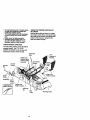
INSTALL SEAT
Adjust seat before tightening adjustment
knob.
• Remove cardboard packing on seat
pan.
• Place seat on seat pan and assemble
shoulder bolt. Tighten shoulder bolt
securely.
• Assemble adjustment knob and flat
washer loosely. Do not tighten.
• Lower seat into operating position and
sit on seat.
• Slide seat until a comfodable position is
reached which allows you to press
clutch/brake pedal all the way down.
• Get off seat without moving its adjusted
position.
• Raise seat and tighten adjustment knob
securely.
" -_ - Seat
Seat Pan
Shoulder
Bolt
Adjustment Knob
CHECK TIRE PRESSURE
The tires on your tractor were ovednflated
at the factory for shipping purposes.
Correct tire pressure is important for best
cuffing performance.
• Reduce tirepressure to PSI shown in
"PRODUCT SPECIFICATIONS" on
page 5 of this manual.
CHECK BRAKE SYSTEM
After you learn how to operate your trac-
tor, check to see that the brake is properly
adjusted. See "TO ADJUST BRAKE" in
the Service and Adjustments section of
this manual.
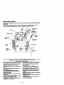
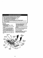
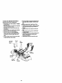
INSTALL MOWER AND DRIVE BELT
Be sure tractor ison level surface and
mower suspension arms are raised with
attachment liftcontrol. Engage parking
brake.
• Cut and remove ties securing anti-sway
bar and belts. Swing anti-sway bar to
left side of mower deck.
• Slide mower under tractor with dis-
charge guard to rightside of tractor.
IMPORTANT: Check belt for proper rout-
ing in all mower pulley grooves. Install
belt into electric clutch pulley groove.
• install one front link in top hole of the
right hand front mower bracket and right
hand front suspension bracket. Retain
with two single loop retainer spdngs as
shown.
• Install second front link in left hand
front suspension bracket only and
retain with single loop retainer spdng as
shown.
• Turn height adjustment knob counter-
clockwise until it stops.
• Lower mower linkage with attachment
liftcontrol.
• Place the left hand suspension arm on
inward pointing deck pin. If necessary,
rock and raise front of mower to align
deck pin with the hole in suspension
arm. Retain with double loop retainer
spdng with loops down as shown.
• Slide left side of mower back and install
the unattached front link in top hole of
the left hand front mower bracket.
Retain with single loop retainer spdng
as shown.
• Place the dght hand suspension arm on
inward pointing deck pin. If necessary,
rock and raise front otmower to align
deck pin with the hole in suspension
arm. Retain with double loop retainer
spring with loops down as shown.
9

• Connectanti-swaybartochassisbrack-
etunder left footrest and retain with
doubleloop _r spring.
• Turn height adjustment knob clockwise
to remove slack from mower suspen-
sion.
• Raise mower to highest position.
Assemble gauge wheels (See..."TO
ADJUST GAUGE WHEELS in the
Operation section of this manual).
CHECK MOWER LEVELNESS
For best cutti_j results, mower should be
properly leveled. See "TO LEVEL
MOWER HOUSING" in the Service and
Adjustments section of this manual.
ShouMer
Ba_
Chassis
Bracket
DoubleLoop
RetainerSpring
(Inward po_r,.g
deck
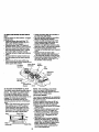
CHECK FOR PROPER POSITION OF
ALL BELTS
See the figures that are shown for replac-
ing motion, mower drive, and mower blade
drive belts in the Service and Adjustments
section of this manual. Vedfythatthe
belts are muted correctly.
Suspension
Arms
Front
Brackets
Gauge
Wheel
3/8 Washer 3/8-16
Center
Locknut
I Use Pliersfor
DoubleLoop
RetainerSpdng
Retainer Springs
Idler
Pulley Discharge Guard
10

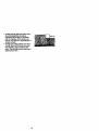
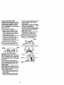
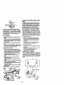
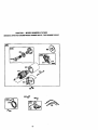
INSTALL MULCHER PLATE
• Install two latch hooks to mulr.her plate
using ecmw, washer, lock washer, and
wold nut as shown.
NOTE: Pre-sssambie weld nut to latch
hook by inserting wold nut from the top
with hook pointingdown.
• Tighten hardware securely.
• Raise and hold deflector shield in up-
right position.
• Place front of mulcher plate over front of
mower deck opening and slide into
place, as shown.
• Hook front latch into hole on front of
mower deck.
• Hook rear latch into hole on back of
mower deck.
_.CAUTION: Do not remove discharge
guard from mower. Raise and hold guard
when attaching mulcher plate and allow it
to rest on plate while in operation.
TO CONVERT TO BAGGING OR
DISCHARGING
Simply remove mulcher plate and store in
a safe place. Your mower is now ready for
discharging or installation of optional
grass catcher accessory.
NOTE: It is not necessary to change
blades. The mulcher blades are designed
for discharging and bagging also.
Weld Nut
fromtheTo_ _ Hook Points •
Weld Ic
Latch
H°ok_:_i / / /It _Lcck
Mulcher _,-_-Screw
Plate
Deflector __
Shle,d
*I CHECKLIST
Please review the following
,/ All assembly instructions have been
completed.
/ No remaining loose parts in carton.
,/Battery isproperly prepared and
charged. (Minimum 1 hour at 6 amps).
,/Seat is adjusted comfortably and tight-
ened securely.
,/All tires am properly inflated. (For ship-
ping purposes, the tires were ovednfiat-
ed at the factory).
,/Be sure mower deck is propedy leveled
side-to-side/front-to-rear for best cuffing
results. (/ires must be properly inflated
for leveling).
,/Check mower and drive belts. Be sure
they are routed properly around pulleys
and inside all belt keepers.
,/Check wiring. See that all connections
are stillsecure and wires are propedy
clamped.
While learning how to use your tractor,
pay extra attention to the following impor-
tant items:
,/" Engine oil is at proper level.
/ Fuel tank is filled with fresh, clean, regu-
lar unleaded gasoline.
/ Become familiar with all controls - their
location and function. Operate them
before you start the engine.
/ Be sure brake system is in safe operat-
ing condition.
11

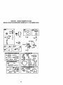
Thesesymbolsmayappearonyourtractororin literaturesuppliedwiththeproduct.
Learnand understandtheirmeaning.
A, =
BA1TERY CAUTION OR
WARNING
ENGINE ON ENGINE OFF
REVERSE FORWARD FAST SLOW
FUEL CHOKE
OIL PRESSURE LIGHTS ON OVER TEMP "11_
UGHT
t
MOWER HEIGHT PARKING BRAKE UNLOCKED MOWER LIFT
LOCKED
r_'= R N
AI'rACHMENT REVERSE NEUTRAL
CLUTCH ENGAGED
ATTACHMENT
IGNITION CLUTCH DISENGAGED
H L (®>_(
HIGH LOW PARffiNG BRAKE
KEEP AREA CLEAR SLOPE HAZARDS
(SEE SAFETY RULES SECTION)
DANGER, KEEP HANDS AND FEET AWAY
FREE WHEEL
(.'_,tom_ Mod_ or.y)
12

KNOW YOUR TRACTOR
READTHIS OWNER'S MANUALAND SAFETY RULESBEFORE OPERATINGYOUR
TRACTOR
Comparethe illustrationswithyourtractortofamiliarizeyourseffwiththelocationsof
vadouscontrolsand adjustments.Save thismanualforfuturereference.
Ignition
Ammeter Switch Position
Attachment
ThrottleControl
Clutch/Brake
Pedal
Lift Lever
Plunger
Attachment
LiftLever
Choke
Control
Brake
Height
Knob
Gear Shift
Lever
Range Shift
ever
Our tractors conform to the safety standards of the Amedcan
National Standards Institute.
A'I-rACHMENT CLUTCH SWITCH: Used
to engage the mower blades, or other at-
tachments mounted to your tractor.
LIGHT SWITCH: Turns the headlights on
and off.
THROTTLE CONTROL: Used to control
engine speed.
CLUTCWBRAKE PEDAL: Used for
doclutching and braking the tractor and
starting the engine.
CHOKE CONTROL: Used when starting a
cold engine.
HEIGHT ADJUSTMENT KNOB: Used to
adjust the mower cutting height.
GEAR SHIFT LEVER: Selects the speed
and .d.d._octionof the tractor.
RANGE SHIFT LEVER: Allows high (H)
and low (L) speed for all forward and
reverse gears.
A'n'ACHMENT LIFT LEVER: Used to
raise and lower the mower dock or other
attachments mounted to your tractor.
LIFT LEVER PLUNGER: Used to release
attachment liftlever when changing its
position.
IGNITION SWITCH: Used for starting and
stopping the engine.
AMMETER: Indicates battery charging (+)
or discharging (-).
PARKING BRAKE: Locks clutclVbrake
intothe brake position.
13

I[_ Theoperationofanytractorcanresultinforeignobjectsthrownintothe I
eyes, which can result in severe eye damage. Always wear safety glasses I
or eye shields while operating your tractor or performing any adjustments or I
repairs. We recommend a wide vision safety mask over spectacles, or stan- I
dard safety glasses. I
HOW TO USE YOUR TRACTOR IMPORTANT: Leaving the ignitionswitch
Your tractor is _luipped with an operator
.presence sensing switch. When engine is
running, any attempt by the operator to
leave the seat without first setting.the
parking brake will shut off the engine.
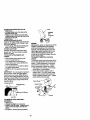
TO SET PARKING BRAKE
• Depress clutch/brake pedal into full
"BRAKE" position and hold.
• Place parking brake lever in "EN-
GAGED" position and release pressure
from clutch/brake pedal. Pedal should
remain in "BRAKE" position. Make sure
parking brake will hold tractor secure.
Push-Into
=Disengaged' AttachmentClutch
Choke
Control SwitchPullOutTo
Ped_ "Ddve"
Podton
Brake
Lever
STOPPING
MOWER BLADES
• To stop mower blades, move attach-
ment clutch switch to "DISENGAGED"
pcaition.
GROUND DRIVE
• To stopground ddve, depress
clutch/brake pedal into full "BRAKE"
position.
• Move gearshift lever to neutral (N)
position.
ENGINE
• Move throttle control to slow position.
NOTE: Failure to move throttle control to
_eoiwpo6ition and allowing engine to idle
re stopping may cause engine to
-bacldire'.
•Tum ign_on key to "OFF" position and
remo.ve key. Always remove key when
leav_ tractor to prevent unauthodzed
use.
• Never use choke to stop engine.
in any position other than =OFF' will cause
the battery to be discharged (dead).
NOTE: Under certain conditions when
tractor is standing idle with the engine run-
ning, hotengine exhaust gases may
cause "browning"of grass. To eliminate
this possibility,always stop engine when
stopping tractor on grass areas.
_. CAUTION: Always stop tractor com-
pletely, as descn'bed above, before leaving
the operator's position; to empty grass
catcher, etc.
THROTTLE CONTROL
Always operate engine at full throttle.
Operating engine at less than full throt-
tle reduces the battery charging rate.
• Full throttle offers the best bagging and
mower performance.
CHOKE CONTROL
Use choke control whenever you are start-
ing a cold engine. Do not use to stad a
warm engine.
• To engage choke control, pull knob out.
Slowly push knob in to disengage.
TO MOVE FORWARD AND BACKWARD
The direction and speed of movement is
controlled by the gearshift lever.
• Start tractor with clutch/brake pedal
depressed and gearshift lever in neutral
(N)position.
• Move gearshift and range shift levers to
desired position.
• Slowly release clutch/brake pedal to
start movement.
IMPORTANT: Bdng tractor to a complete
stop before shifting or changing gears.
Failure to de so will shorten the useful life
of your transaxle.
TO ADJUST MOWER cu'rrlNG HEIGHT
The cuffing height is controlled by turning
the height adjustment knob in desired
direction.
• "rum knob clockwise (C,) to raise cutting
neight.
Turn knob counterclockwise (0) to
lower cuffing height.
The cutting height range is approximately
1-1/2" to 4-I/2". The heights are mea-
sured from the ground to the blade tip with
the engine cot running. These heights are
approximate and may vary depending
upon soil conditions, height of grass and
14 types of grass being mowed.

• Theaveragelawnshouldbecutto
approximately2-1/2inchesdudngthe
coolseasonandtoover3inchesduring
hotmonths.Forhealthierandbetter
lookinglawns,mowoftenandafter
moderate growth.
• For best cutting performance, grass
over 6 inches in height should be
mowed twice. Make the first cut rela-
tively high; the second to desired height.
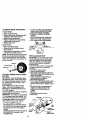
" TO ADJUST GAUGE WHEELS
Gauge wheels are properly adjusted
when they are slightly oft the ground when
mower is at the desired cutting height in
operating position. Gauge wheels then
keep the deck in proper position to help
prevent scalping in most terrain condi-
tions.
• Adjust gauge wheels with tractor on a
flat level surface.
• Adjust mower to desired cutting height
(See "TO ADJUST MOWER CU'I-I'ING
HEIGHT" in the Operation section of
this manual).
• With mower in desired height of cut po-
sition, gauge wheels should be assem-
bled so they are slightly off the ground.
Install gauge wheel in appropriate hole
with shoulder bolt, 3/8 washer, and 3/8-
16 Iocknut and tighten securely.
• Repeat for opposite side installing
gauge wheel in same adjustment hole.
Bracket
3/8-16
Locknut Shoulder Bolt
3/8 Washer Gauge Wheel
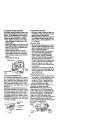
TOO -E; ATEMOWE.
Your tractor is equipped with an operator
presence sensing switch. Any attempt by
the operator to leave the seat with the
engine running and the attachment clutch
engaged will shut off the engine.
• Select desired height of cut.
• Lower mower with attachment lift con-
treL
• Start mower blades by engaging attach-
ment clutch control.
• TO STOP MOWER BLADES - disen-
gage attachment clutch control.
_,CAUTION: Do not operate the mower
without either the entire grass catcher, on
mowers so equipped, or the discharge
guard in place.
AttachmentClutch AttachmentUft Lever
SwitchPullOutTo HighPosl_on
, . . / Low
I _°_li_,,Y,._-t II II f Dischargs
_'_,_ ")"W-_ 7 _-JrTi\ Guard
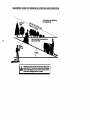
TO OPERATE ON HILLS
_,CAUTION: Do not drive up or down
hills with slopes greater than 15° and do
not drive across any slope. Use the slope
guide provided at the back ofthis manual.
-• Choose the slowest speed before start-
ing up or down hills.
• Avoid stopping or changing speed on
hills.
• If slowing is necessary, move throttle
control lever to slower position.
• If stopping is absolutely necessary, push
clutch/brake pedal quickly to brake posi-
tion and engage parking brake.
• Move gearshift lever to I st gear and
range shift laver to low (L) position, Be
sure you have allowed room for tractor
to roll slightly as you restart movement.
• To restart movement, slowly release
parking brake and clutch/brake pedal.
• Make all tums slowly.
TO TRANSPORT
• Raise attachment liftto highest position
with attachment liftcontrol.
• When pushing or towing your tractor, be
sure gearshift lever isin neutral (N)
position.
• Do not push or tow tractor at more than
five (5) MPH.
NOTE: To protect hood from damage
when transpoding your tractor on a truck
or a trailer, be sure hood isclosed and
secured to tractor. Use an appropriate
means of tying hood to tractor (rope, cord,
etc.).
15

TOWINGCARTSANDOTHER
ATTACHMENTS
Towonlytheattachments thatarerecom-
mandedbyand complywithspecifications
ofthe manufacturerofyourtractor.Use
commonsensewhentowing.Tooheavyof
a load,whileon a slope,isdangerous.
"13roscanlosetractionwiththegroundand
causeyouto losecontrolofyourtractor.
BEFORE STARTING THE ENGINE
CHECK ENGINEOIL LEVEL
The engine in your tractor has been
shipped, from the factory, already filled
with summer weight oil.
Check engine oil with tractor on level
ground.
• Unthreed and remove oil fill cap/dip
suck;,wipe oil off. Reinsed the dipstick
intothe tube and rest oil fill cap on the
tube. Do not thread the cap onto the
tube. Remove and read oil level. If nec-
essary, add oil until "FULL" mark on
dipstick is reached. Do not overfill.
• For cold weather operation you should
change oil for easier starting (See "OIL
VISCOSITY CHART" in the Customer
Responsibilities section of this manual).
• To cnange engine oil,see the Customer
Responsibilities section in this manual.
ADO GASOLINE
• Fillfuel tank. Use fresh, clean, regular
unleaded gasoline with a minimum of 87
octane. (Use of leaded gasoline will
increase carbon and lead oxide
deposits and reduce valve life). Do not
mix oil with gasoline. Purchase fuel in
quantities that can be used within 30
days to assure fuel freshness.
IMPORTANT: When operating in tempera-
tures below 32°F(0°C), use fresh, clean
winter grade gasoline to help insure good
;old weather starting.
A WARNING: Experience indicates that
zlcoholblended fuels (called gasohol or
Jsing ethanol or methanol) can attract
noisture which leads to separation and
ormation of acids during storage. Acidic
]as can damage the fuel system of an
=.nginewhile in storage. To avoid engine
)roblems, the fuel system should be emp-
ied before storage of 30 days or longer.
)rein the gas tank, start the engine and let
i run untilthe fuel lines and carburetor are
_mpty. Use freshJuel next season. See
;torege Instructions for additional
fformati_o, Never use engine or
arburetor cleaner products in the fuel
_nk or permanent damage may occur.
16
,_CAtrrlON: nil to bottom of gas tank
filler neck. Do not overfill. W'c)e off any
spilled oil or fuel. Do not store, spill or use
gasoline near an open flame.
TO START ENGINE
When starting the engine for the first time
or ifthe engine has run out of fuel, itwill
take extra cranldng time to move fuel from
the tank to the engine.
• Sit on seat in operating position,
depress clutch/brake pedal and set
paddng brake.
• Place gear shift lever in neutral (N)
position.
• Move attachment clutch to "DISEN-
GAGED" position.
• Move throttlecontrol to fast position
Pull choke control out for a cold engine
start attempt. For a warm engine start
attempt the choke control may not be
needed.
NOTE: Before starting, read the warm and
cold starting procedures below.
• Insert key into ignition and turn key
clockwise to =START" position and
release key as soon as engine starts.
Do not run starter continuously for more
than fifteen seconds per minute. If the
engine does not start after several
attempts, push choke control in wait a
few minutes and try again. If engine still
does not start, pull the choke control out
and retry.
WARM WEATHER STARTING (50 ° F
AND ABOVE)
• When engine starts, slowly push choke
control in untilthe engine begins to run
smoothly. If the engine starts to mn
roughly,pull the choke control out slight-
ly for a few seconds and then continue
to push the control in slowly.
• The attachments and ground drive can
now be used. If the engine does not
accept the load, restart the engine and
allow it to warm up for one minute using
the choke as described above.

COLD WEATHER STARTING (50° FAND
BELOW)
• When engine starts, slowly push choke
control in un_l the engine begins to run
smoothly. Continue to push the choke
control in smell steps allowing the
engine to accept small changes in
speed and load, until the choke control
is fully in. If the engine starts to run
roughly, pull the choke control out slight-
lyfor a few seconds and then continue
to push the control in slowly.This may
require an engine warm-up period from
several seconds to several minutes,
depending on the temperature.
• The attachments can be used during
the engine warm-up period and may
require the choke control be pulled out
slightly.
NOTE: A high altitude (above 3000 feet)
or in cold temperatures (below 32 F) the
carburetor fuel mixture may need to be
adjusted for beat engine performance.
See "TO ADJUST CARBURETOR" in the
Service and Adjustments section of this
manual.
• Do notmowgrasswhenitiswet.Wet
grasswillplugmowerandleave unde-
elrable clumps,Allowgrasstodry
beforemowing.
• Always operate engine at full throttle
when mowingto assurebettermowing
performance andproperdischargeof
materiel. Regulategroundspeedbyse-
lectinga lowenoughgeartogivethe
mowerthe bestcuttingperformanceas
well asthequalityofcutdesired.
• Whenoperatingattachments,selecta
groundspeedthatwillsuittheterrain
andgivebestperformanceofthe at-
tachmentbeingused.
MOWING TIPS
• Tire chains cannot be used when the
mower housing is attached to tractor.
• Mower should be properly leveled for
best mowing performance. See =TO
LEVEL MOWER HOUSING" in the
Service and Adjustments section of this
manual
• The left hand side of mower should be
used for trimming.
• Drive so that clippings are discharged
onto the area that has been cut. Have
the out area to the right of the tractor.
This will result in a more even distribu-
ti0_of clippings and more uniform cut-
ting.
• When mowing large areas, start by turn-
ing to the right so that clippings will dis-
charge away from shrubs, fences, drive-
ways, etc. After one or two rounds, mow
in the opposite direction making left
hand turns until finished.
• It grass is extremely tall, it should be
mowed twice to reduce load and possi-
ble fire hazard from dried clippings.
Make first cut relatively high; the second
to the desired height.
MULCHING MOWING TIPS
IMPORTANT: For best performance, keep
mower housing free of built-up grass and
trash. Clean after each use.
• The special mulching blade will recut
the grass clippings many times and
reduce them in size so that as they fall
onto the lawn they will disperse into the
grass and not be noticed. Also, the
mulched grass will biodegrade quickly
to provide nutrients forthe lawn. Always
mulchwith your highest engine (blade)
speed as this will provide the best recut-
ting action of the blades.
• Avoid cuttingyour lawn when itis wet.
Wet grass tends to form clumps and
interferes with the mulching action. The
best time to mow your lawn is the early
aftemoon. At this time the grass has
dried and theJlewly cut area will not be
exposed to the direct sun.
• For best results, adjust the mower cut-
ting height so that the mower cuts off
only the tpp one-third of the grass
blades. For extremely heavy mulching,
reduce your width of cut on each pass
and mow slowly.
17

• Certaintypeeofgrassandgreescond'P
tionsmayrequirethatanareabe
mulchedasecondtimetocompletely
hidethec{ipping_Whendoingasec-
ondcut,mowacrossorperpendicularto
thefirstcutpath.
• Change your cutting pattem from week
to week. Mow north to south one week
then change to east to west the next
week. This will help prevent matting and
graining of the lawn.
18

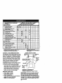
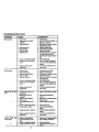
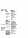
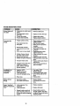
MAINTENANCE SCHEDULE Z__f___S E_VIC E D
FILL IN DATES
AS YOU COMPLETE
REGULAR SERVICE ATES
Check Brake Operation V'
Check Tim Pressure 1_ If
Check Operator Presence and
T Interlock Systems (l_
R CheckforLooseFastenara t/ I/,
A Shaq>ecVReplsce Mower Blades Id#'4
T Lubrication Chart V' I_ /
0 Check Battery Level l_i
R C_anBatteryandTerminals ll/ IV_
Check Transaxla Cooi'_g I_/
Adjust Elsde Belt(s) Te ns'_n 11_$
AdJust Motion Drive Beh($) Tension (_s
Check Engine Oil Level I_ I_
Change Engine Oi_ I_1,=,: V p
E Clean Air Fk*ter I_a
N Clean Air Screen ik_z
G Inspect MuffierlEpark An'ester
HE Replace Oil Filter (If equipped) I_1,;
Clean Engine Cooling Fins I_2
Repklce Spark Plug _2 V'
Replace Air Filter Paper Cartr_ge
Replace Fuel Fitter ,
1 - Change r_te _qm whe*lopemL_ngunders beery Io_ 0t Inhl_ ambienl _turl4. S. ffeq_pp_ _11h_mmbll tr/llem.
2. Sm',_e moreon=nwh_,eoperating in dlrlyor dm_/¢:o_ltk)n_
3. If equlppedwith ogflier. ©hangeolle.4er/50 howe.
4 - Repll¢o bia4ee mote often when mowing in m_dy sda.
6 - Not r=_e_ # _ wi_ _ b_tq_
7. T_ _ L,de plvolboltto _ ft._. m_,_'num.
Do n¢4e_wl_ht_.
GENERAL RECOMMENDATIONS
The warranty on this tractor does not cover
items that have been subjected to operator
abuse or negligence. To receive full value
from the warranty, operator must maintain
tractor as instructed in this manual. Some
adjustments will need to be made periodi-
cally to propedy maintain your tractor.
All adjustments in the Service and
Adjustments section of this manual should
be c'hecl_edat least once each season.
• Once a year you should replace the
spark plug, clean or replace air filter, and
check blades and belts for wear. A new
spark plug and clean air filter assure
proper air-fuel mixture and help your
engine run better and last longer.
BEFORE EACH USE
• Check engine oil level.
• Check brake operation.
• Check tire pressure.
LUBRICATION CHART
Zerk Zerk
Beadn
Wheel
Beadng
Zerk
O SAE 30 or10w30 MotorOIL
O GeneralPurposeGrease
• Refer toMaintenance"Engine"Section
IMPORTANT: Do not oil or grease the pivot
points which have special nylon bear-ings.
Viscous lubricants will attract dust and dirt
• Chec koperator presence and interlock that will shorten the life of the serf-lubricating
sy..stemsfor proper operation, bearings. If you feel they must be lubricated,
• CT_eckfor loose fasteners, use only a dry, powdered graphite type lubri-
cant sparingly.
19

TRACTOR
Alwaysobee_vesafetyruleswhenper-
forming any maintenance.
BRAKE OPERATION
If tractor requires more than six (6) feet
stopping distance at high speed in highest
gear, then broke must be adjusted. (See
"1"OADJUST BRAKE" in the Service and
Adjustments section ofthis manual).
TIRES
• Maintain proper air pressure in all tires
(See "PRODUCT SPECIFICATIONS" on
page 5 of this manual).
• Keep tires free of gasoline, oil, or insect
control chemicals which can harm rub-
ber.
• Avoid stump6, stones, deep ruts, sharp
objects and other hazards that may
cause tire damage.
NOTE: To seal tire punctures and prevent
flat tires due to slow leaks, tire sealant
may be_urchased from your local parts
dealer. Tire sealant also prevents tire dry
rotand corrosion.
OPERATOR PRESENCE SYSTEM
Be sure that operator presence and inter-
lock systems are working properly. Ifyour
tractor does notfunction as described
below, repair the problem immediately.
• The engine should not start unless the
clutch/brake pedal is fully depressed
and attachment clutch control is in the
disengaged position.
• When the engine is running, any
attempt by the operator to leave the
seat without first setting the parking
brake should shut off the engine.
• When the engine is running and the
attachment clutch isengaged, any
attempt by the operator to leave the
seat should shut off the engine.
• The attachment clutch should never
operate unless the operator is in the
seat.
3LADE CAR-E
"or best results mower blades must be
:eptsharp. Replace bent or damaged
)lades.
}LADE REMOVAL
Raise mower to highest position to allow
access to blades.
Remove hex bolt, lock washer and fiat
washer Securing blade.
Install new or re,sharpened blade with
trailing edge up towards deck as shown.
_PORTANT: To ensure proper assembly,
enter hole in blade must align with star
n mandrel assembly.
Reassemble hex bolt, lock washer and
flat washer in exes_ order as shown.
• Tighten boltsecurely (27-35 Ft. Lho.
to[orque-ue).
IMPORT/ANT: Blade belt is Grade 8 heat
treated.
TrailingEdge MandrelAssembly
Blade Center
Hole
._. Star
_.._--H ex Bolt
°AGrade8heat treatedboltcanbe
identifiedbysixline_onthebolthead.
TO SHARPEN BLADE
NOTE: We do not recommend sharpening
blade, but ifyou do, be sure the blade is
balanced.
Care should be taken to keep the blade
balanced. An unbalanced blade will cause
excessive vibration and eventual damage
to mower and engine.
• The blade can be sharpened with a file
or on a grinding wheel. Do not attempt
to sharpen while it is on the mower.
• To check blade balance, you will need a
5/8" diameter steel bolt, pin, or a cone
balancer. (When using a cone balancer,
follow the instructionssupplied with bal-
ancer).
NOTE: Do not use a nail forbalancing
blade. The lobes of the center hole may
appear to be centered, but are not.
• Slide blade onto an unthreaded portion
of the steel boltor pin and hold the bolt
or pin'parallal with the ground. If blade
isbalanced, itshould remain in a hori-
zontal positlan. If either end of the blade
moves downward, sharpen the heavy
end untilthe blade is balanced.
""_._ Blade
5/8"Boif _ ._
BATTERY
Your tractor has a battery charging system
which is sufficient for normal use.
However, periodic charging ofthe battery
with an automotive charger will extend its
life.
• Keep battery and terminals clean.
• Keep bettery boltstight.
• Keep small vent holes open.
• Recharge at 6-10 amperes for 1 hour.
2O
Page is loading ...
Page is loading ...
Page is loading ...
Page is loading ...
Page is loading ...
Page is loading ...
Page is loading ...
Page is loading ...
Page is loading ...
Page is loading ...
Page is loading ...
Page is loading ...
Page is loading ...
Page is loading ...
Page is loading ...
Page is loading ...
Page is loading ...
Page is loading ...
Page is loading ...
Page is loading ...
Page is loading ...
Page is loading ...
Page is loading ...
Page is loading ...
Page is loading ...
Page is loading ...
Page is loading ...
Page is loading ...
Page is loading ...
Page is loading ...
Page is loading ...
Page is loading ...
Page is loading ...
Page is loading ...
Page is loading ...
Page is loading ...
Page is loading ...
Page is loading ...
Page is loading ...
Page is loading ...
Page is loading ...
Page is loading ...
Page is loading ...
Page is loading ...
-
 1
1
-
 2
2
-
 3
3
-
 4
4
-
 5
5
-
 6
6
-
 7
7
-
 8
8
-
 9
9
-
 10
10
-
 11
11
-
 12
12
-
 13
13
-
 14
14
-
 15
15
-
 16
16
-
 17
17
-
 18
18
-
 19
19
-
 20
20
-
 21
21
-
 22
22
-
 23
23
-
 24
24
-
 25
25
-
 26
26
-
 27
27
-
 28
28
-
 29
29
-
 30
30
-
 31
31
-
 32
32
-
 33
33
-
 34
34
-
 35
35
-
 36
36
-
 37
37
-
 38
38
-
 39
39
-
 40
40
-
 41
41
-
 42
42
-
 43
43
-
 44
44
-
 45
45
-
 46
46
-
 47
47
-
 48
48
-
 49
49
-
 50
50
-
 51
51
-
 52
52
-
 53
53
-
 54
54
-
 55
55
-
 56
56
-
 57
57
-
 58
58
-
 59
59
-
 60
60
-
 61
61
-
 62
62
-
 63
63
-
 64
64


Craftsman 917.271080 Owner's manual
- Category
- Lawnmowers
- Type
- Owner's manual
- This manual is also suitable for
Ask a question and I''ll find the answer in the document
Finding information in a document is now easier with AI
Related papers
-
Craftsman 917.28723 Owner's manual
-
-
-
-
-
-
-
-
Other documents
-
Poulan 917279820 Owner's manual
-
Sears 917.257632 User manual
-
-
-
-
-
-
-
-