SOUNDSTRC@
T
E
C
H
N 0 L 0 G
1
E
s
SOUNDSTREAM TECHNOLOGIES
120 Blue Ravine Road
-
Folsom
-
California 95630 USA
ph 916.351.1288
.
fax 916.351.0414
revA
-
YV98
WWV.
SOUfdDSTREAM.COM
S@UNDSTREW/l@
1
T
E
C
H
N
0 L 0 G I
E
S
,
RUBICON
204
404
604
41312
Channel
Power Amplifiers
Owner’s Manual
and
Installation Guide

Conaratulations!
You now own the Soundstream
RUBICON
amplifier,
the
product
of
an un-
compromising design and engineering philosophy, Your Soundstream
RUBICON amplifier will outperform any other amplifier in the
world.
To maximize the performance of your system, we recommend that you thor-
oughly acquaint yourself with its capabilites and features. Please retain this
manual and your sales receipt for future reference.
Soundstream amplifiers are the result of American innovation and the high-
est quality control standards. When properly installed, they will provide you
with many years of listening pleasure. Should your amplifier ever need ser-
vice or replacement due to theft, please record the following information which
will help protect your investment.
Model and Serial #
Dealer’s Name
Date of Purchase
Installation Shop
Installation Date
/
CAUTION!
Prolongsd
listening at high
levels
may result in hearing
luss,
Even
though
y~~~new
Soundstraam
Rub&on
amplifiersounds
better than anything
yw’ve
ever heard,
exwcise
w&kx~
to
prevent hearing damage.
Table of Contents
Design Features
.......................................................
p4-5
RUBICON
Amplifier Diagram
..............................
~6-7
RUBICON
Amplifier Diagram
..............................
p 8 -9
RUBICON
Amplifier Diagram
..............................
p 10
-11
Crossover Adjustments
.............................................
P
12
Hawkins Bass
ControlTM
Theory and Use
..................
P
18
Installation:
Speaker Output Modes
..........................
P
14
Installation:
Balanced/Unbalanced Inputs
..................
PI5
Wiring
....................................................................
Pl6
Installation: Mounting
................................................
Pl7
Installation:
Level Setting and Front Spoiler
..............
p 18
Sample System Diagrams
........................................
p 19-21
Protection Circuitry, Service and Troubleshooting..
....
p 22
Specifications
...........................................................
P
23

RUBITM(_Rapid-Be
@ranched
_knpulse)
This new proprietary power
sup-
ply topology eliminates “power sags” during low frequency reproduction
by rapidly increasing the duty cycle, stabilizing the power supply and
allowing it to deliver the power required when reproducing low frequen-
cies. Also, greater reserve gate power is stored for low voltage condi-
tions that occur during extreme conditions.
STACTTM
(STabilized
Apex
Qurent
_Topology)
Reduces power supply
stress by 50%. Typical designs degrade the stereo image due to phase
reversal of even-order harmonic distortion that occurs between the in-
verted channels. In the STACT design, inversion is done at the power
amplifier drive stage. Since the fully symmetrical power amplifier pro-
duces no even-harmonic distortion itself and all preamplifier circuitry is
run completely in-phase, no even harmonic distortion phase reversal
occurs.
TridentTM
Protection Topology provides three types of protection:
I.
Output protection against short circuits or improper loads.
2. Ground fault detection: Shuts down the amplifier when a significant
voltage
(>
5Volts)
fluctuation occurs between electrical (turn-on lead)
and battery ground.
3. Thermal Protection: Puts the amplifier into thermal rollback or shuts
the amplifier down in extreme thermal conditions.
Hawkins Bass Control provides a focused subwoofer boost
(O-9dB
at
45Hz) and routes otherwise wasted amplifier power back to the audible
bandwidth.
Harmonic Bass Alignment
TM
The 2nd and 3rd order harmonic peaks
are critically aligned to fundamental peaks at low frequencies. This
produces tighter, more accurate bass reproduction.
Drive Delay II
TM
Amplifier section powers up 2 to 3
seconds after
the
power supply eliminating turn-on pops. Turn off process is
reversed:
amplifier section turns off first, followed by the power
supply.
Dynamically Optimized Power Grid
TM
.
Power grid is evenly distrib-
uted between primary and secondary power supplies,
providing greater
dynamics and improved
RF
filtering.
4
ChassisinkTM All transistors are ideally located and sandwiched be-
tween the circuit board and the heatsin k to provide cool efficient ampli-
fier operation.
Differentially Balance RCA Input eliminates ground loop related noise
in the audio.
Fully Balanced 6-pin DIN Input (604) for professional-quality perfor-
mance and noise cancellation. The
6-pin
DIN plug carries
(k)
signal
information for Left and Right channels, audio ground, and
=t
15 Vdc to
operate the Soundstream BLT
I
BLT4 Balanced Line Transmitters and
Balanced X.0 crossovers.
Output Clipping Indicators (604) indicate clipping on the output stage
of the amplifier. Monitoring the clipping indicators allows the user to
achieve maximum SPL without clipping the amplifier.
Continuously Variable Crossover Networks: 12
dB/Octave
highpass
variable from 65 to 220 Hz, and 24 dB/Octave lowpass crossovers vari-
able from 30 Hz to 120 Hz. (12 dB/Octave lowpass on RUBICON204)
Flexible Dual Input Level Control allows 300
mV
to 5 V input sen-
sitivity.
Symmetrical Discrete Balanced Class A Drive Boards Auto-adjust
for linear performance while driving low impedance loads.
Removable Front Spoiler allows for stealth installation of RCA, Bal-
anced Line, Speaker and Power wiring.
5

TOP
VlEW
FRONTVIEW
BonoMvlEw(F3v4Tuu)
RUBICON
-
i--w_
/
t
I
n
-16 ,
1.
2.
3
.
4
.
5.
6.
7.
0.
9
lb.
Il.
12.
13.
14.
15.
16.
17.
18.
19.
20.
21.
22.
KEY TO CALLOUTS
FUSE LED
-
Indicates blown
fuse.
POWER LED
-
Indicates amplifier power.
Subsonic
/
Hawkins Bass Control Switch
-
“SUB SONIC” to engage
the Sub Sonic filter at 13 Hz. “Hawkins Bass Control” to engage the high
pass filter
@
45 Hz with built-in boost at
+6dB
for optimum bass for any
Low Pass channel.
XOVER
Switch
-
(Channels
l&2)
Select “L.P.” for use with the internal low
pass filter, “IN” for use with the internal high pass filter, or “OUT” for use
with external crossover.
XOVER
Switch
-
(Channels
3&4)
Select “L.P.” for use with the internal low
pass filter, “H.P.” for use with the internal high pass filter, or “OUT” for use
with external crossover.
Inputs
-
Right and left channel RCA inputs for channels
3&4.
Input
LEVEL
-
Channels
3&4
input level control.
High Pass Control Adjustment
-
(Channels
3&4)
crossover frequency
control for the internal high pass filter.
Speaker Connection Terminal
-
Speaker connections for Ch’s
3&4.
Inputs
-
Right and left channel RCA inputs for channels
l&2.
Input LEVEL
-
Channels
l&2
input level control.
Low Pass Control Adjustment
-
Crossover frequency control for the in-
ternal low pass filter. Applies to any channel with the low pass filter en-
gaged.
High Pass Control Adjustment
-
(Channels l&2) crossover frequency
control for the internal high pass filter.
LINE OUTPUTS
-
Full range outputs to external amplifier. Note: Signal is
driven from channel
l&2
inputs.
Speaker Connection Terminal
-
Speaker connections for Ch’s l&2.
REMOTE
-
Remote turn-on input from the head unit. Accepts
+12V.
GND
-
Main ground connection. Bolt to a clean chassis point in the
vehicle.
+12V
-
Connected to a fuse or circuit breaker, then to the battery’s positive
terminal
Main Fuse
-
Main power supply fuses.
Stereo/Mono Switch
-
(Channels
l&2)
Select “MONO” for bridged mono
output (use right RCA input only). Select “STEREO” for stereo output.
Channels
3&4
INPUT SELECT
-
Selectable inputs from internal (from
channels
l&2)
or external (from channels
3&4
local RCA inputs).
Stereo/Mono Switch
-
(Channels
3&4)
Select “MONO” for bridged mono
output (use right RCA input only). Select “STEREO” for stereo output.

Top View
RUBlCON404
Front View
8
Bottom View
1.
2.
3.
4.
5.
6.
7.
8.
9.
10.
11.
12.
13.
14.
15.
16.
17.
18.
19.
20.
21.
22.
KEY TO CALLOUTS
Power LEO
-
Indicates amplifier power, either in High Power or Auto High
CWWt.
Subsonic
/
Hawkins Bass Control Switch
-
“SUB SONIC” to engage
the Sub Sonic filter at 13 Hz.
‘“Hawkins Bass Control” to engage the high
pass filter
@
45 Hz with variable boost (Q) for optimum bass for any chan-
nel in Low Pass.
XOVER Switch
-
(Channels
l&2)
Select “L.P.” for use with the internal low
pass filter, “IN” for use with the internal high pass filter, or “OUT” for use
with external crossover.
Channels
3&4
INPUT SELECT
-
Selectable inputs from internal (from
channels
l&2)
or external (from channels 3&4 local RCA inputs).
XOVER Switch
-
(Channels 3&4) Select “L.P.” for use with the internal low
pass filter, “H.P.” for use with the internal high pass filter, or “OUT” for use
with external crossover.
Inputs
-
Right and left channel RCA inputs for channels 3&4.
Input LEVEL
-
Channels 3&4 independent left and right input level control.
High Pass Control Adjustment
-
(Channels 3&4) crossover frequency
control for the internal high pass filter.
Speaker Connection Terminal
-
Speaker connections for Ch’s 3&4.
Inputs
-
Right and left channel RCA inputs for channels
l&2.
Input LEVEL
-
Channels
l&2
independent left and right input level control.
High Pass Control Adjustment
-
(Channels
l&2)
crossover frequency
control for the internal high pass filter.
Low Pass Control Adjustment
-
Crossover frequency control for the
internal low pass filter.
Applies to any channel with the low pass filter
engaged.
Hawkins Bass Control “Boost” Adjustment
-
Varies from 0 to
+9
dB
of
boost when the Hawkins Bass Control is engaged. Note: Applies to any
channel with the low pass filter engaged.
LINE OUTPUTS
-
Full range outputs to external amplifier. Note: Signal is
driven from channel
l&2
inputs.
Speaker Connection Terminal
-
Speaker connections for Ch’s
l&2.
REMOTE
-
Remote turn-on input from the head unit. Accepts
+12V.
GND
-
Main ground connection.
Bolt to a clean chassis point in the
vehicle.
+12V
- Connected to a fuse or circuit breaker, then to the battery’s positive
terminal
Main Fuse
-
Main power supply fuses.
Stereo/Mono Switch
-
(Channels
l&2)
Select “MONO” for bridged mono
output (use right RCA input only). Select “STEREO” for stereo output.
Stereo/Mono Switch
-
(Channels 3&4) Select “MONO” for bridged mono
output (use right RCA input only). Select “STEREO” for stereo output.

._-
Top View
Front View
60
ttom View
10
1.
2.
3.
4.
5.
6.
7.
8.
9.
IO.
11.
12.
13.
14.
15.
16.
17.
18.
19.
20.
21.
22
23.
24.
25.
26.
27.
28.
29.
30.
31.
32.
KEY TO CALLOUTS
FUSE LED
-
Indicates blown
fluse.
Power LED
-
indicates amplifier power, either in High Power or Auto High Current.
Subsonic
/
Hawkins Bass Control Switch
-
“SUB SONIC” to engage the Sub Sonic
filter at 13 Hz.
“Hawkins Bass Control” to engage the high pass filter
@
45 Hz with
variable boost
(Q)
for optimum bass for any channel in Low Pass.
Clip Indicators
-
(Channels
l&2)
Indicates the signal output level is too high and the
output stage of the amplifier is clipping.
XOVER Switch
-
(Channels
l&2)
Select
“L.P.”
for use with the internal low pass filter,
“IN” for use with the internal high pass filter, or “OUT” for use with external crossover.
Left Channel Balanced/Unbalanced Input Selector
-
(Ch 1) Select “BALANCED” to
use the 6 pin Balanced signal input. Select “UNBALANCED” to use the RCA signal inputs.
Right Channel Balanced/Unbalanced Input Selector
-
(Ch 2) Select “BALANCED” to
use the 6 pin Balanced signal input. Select “UNBALANCED” to use the RCA signal inputs.
Clip Indicators
-
(Channels
3&4)
Indicates the signal output level is too high and the
output stage of the amplifier is clipping.
XOVER Switch
-
(Channels
3&4)
Select
“L.P.”
for use with the internal low pass filter,
“HP.” for use with the internal high pass filter, or “OUT” for use with external crossover.
Left
#Channel
Balanced/Unbalanced Input Selector
-
(Ch 3) Select “BALANCED” to
use the 6 pin Balanced signal input. Select “UNBALANCED” to use the RCA signal inputs.
Right Channel Balanced/Unbalanced Input Selector
-
(Ch 4) Select “BALANCED” to
use the 6 pin Balanced signal input. Select “UNBALANCED” to use the RCA signal inputs.
Inputs
-
Right and left channel RCA inputs for channels
3&4.
Balanced Signal Input Connector
-
(Channels
3&4)
6-Pin Balanced input connector
for use with the Soundstream
BLT/BLT4
Balanced Line Trasmitter or X.0 crossover.
Input LEVEL
-
Channels
3&4
independent left and right input level control.
High Pass Control Adjustment
-
(Channels
3&4)
crossover frequency control for the
internal high pass filter.
Speaker Connection Terminal
-
Speaker connections for Ch’s
3&4.
Inputs
-
Right and left channel RCA inputs for channels
l&2.
Balanced Signal Input Connector
-
(Channels
l&2)
6-Pin
Balanced input connector
for use with the Soundstream BLT/BLT4 Balanced Line Trasmitter or X.0 crossover.
Input LEVEL
-
Channels
l&2
independent left and right input level control.
High Pass Control Adjustment
-
(Channels
l&2)
crossover frequency control for the
internal high pass filter.
Low Pass Control Adjustment
-
Crossover frequency control for the internal low
pass filter. Applies to any channel with the low pass filter engaged.
Hawkins Bass Control “Boost” Adjustment
-
Varies from 0 to
+9
dB
of boost when
the Hawkins Bass Control is engaged. Note: Applies to any channel with the low pass
filter engaged.
Subwoofer Level Control
-
Additional level control (k6dB) to any channel receiving
information from the low pass filter.
Line Outputs
-
Full range outputs to external amplifier. Note: Signal is driven from
channel
l&2
inputs.
Speaker Connection Terminal
-
Speaker connections for Ch’s
l&2.
REMOTE
-
Remote turn-on input from the head unit. Accepts
+12V.
GND
-
Main ground connection. Bolt to a clean chassis point in the vehicle.
+12V
-
Connected to a fuse or circuit breaker, then to the battery’s positive terminal
Main Fuse
-
Main power supply fuses.
Stereo/Mono Switch
-
(Channels
l&2)
Select “MONO” for bridged mono output (use
right level and RCA input only). Select “STEREO” for stereo output.
Channels
3&4
INPUT SELECT
-
Selectable inputs from internal (from channels
l&2)
or
external (from channels
3&4
local RCA inputs).
Stereo/Mono Switch
-
(Channels
3&4)
Select “MONO” for bridged mono output (use
right level and RCA input only). Select “STEREO” for stereo output.
11

Hawkins Bass Control
-
Theory and
Use
The
RUBICON204,404
and 604 amplifiers incorporates an on-board stag-
gered electronic crossover, with full range RCA outputs to drive an external
amplifier. No external electronic crossover is necessary. The high and low
pass portions of the crossover can be set independently of one another.
In many car audio installations, there is a tendency for a
“midbass
boom.”
Because of their interior dimensions, most
cars will resonate or ring at these
midbass frequencies. If we design the system so there is reduced ouput
in
this region, the final response is very smooth and natural sounding. The
high pass crossover is independently variable from 65 to 220 Hz at 12
dB/
Octave, and low pass crossover is independently variable from 30 to 120 Hz
at 24
dB/Octave.
(12 dB/Octave lowpass on RUBICON204)
For initial crossover setup, try setting the low pass filter to approximately
60 Hz, and the high pass filter to approximately
100
Hz. Change the cross-
over points to accommodate a good mixture of frequency response, power
handling, and personal preference.
12
dB/Octave
High Pass
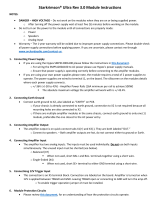
Hawkins Bass Control (variable) is
a
unique subwoofer control
circuit included with the Soundstream
RUBICON
and 604 am-
plifier. It is capable of removing subsonic energy in program ma-
terial below 45 Hz at 12 dB/Octave, while boosting subwoofer
frequencies. The circuit consists of two controls. One engages a
sub sonic High Pass filter at 45 Hz, and the other adjusts the
amount of boost (0 to
+9
dB).
The Hawkins Bass Control func-
tions on either pair of channels
(l&2
or
38~4)
if their low pass filter
is engaged.
The Boost control adjusts the amount of level applied at the set
---
rll[lj
I
SUB
HANKINS
SON C
l
BASS
CONTROL
HAWKINS
BASS
CONTROL
0
0’
6
.dB
Q
FIG. 1
frequency,
and is adjustable from 0 to
+9
dB
(see figure 2). When the boost is set
to 0, Hawkins Bass Control acts as a sub sonic filter only. The simple act of
removing potentially harmful low frequencies IO
can improve system output by as much as 3
5
dB.
NOTE: The RUBlCON204 contains
O
Hawkins Bass Control
(rixecj)
which is
dB
-5
similiar to the variable version except the
1::
boost is fixed at
+6dB.
-20,
I
I
Application
-25
_
-
.
-
L
I
Subwoofer drivers in general have excellent
-3010
Frequency (Hz) 50 100 200
power handling characteristics over their opera-
FIG. 2 VARIABLE BOOST
tional bandwidth. This bandwidth is determined by many factors, including driver
design, and enclosure type. It is possible to overdrive any subwoofer driver by
sending powerful signals outside of its operational bandwidth. These potentially
damaging signals can be removed by adding a subsonic filter. Figure 3 shows
the effectiveness of the Hawkins Bass Control on woofer excursion in a vented
enclosure. The woofer travels 7.5 mm at 10 Hz. With Hawkins Bass Control
properly adjusted, this excursion can be reduced to less than 1 mm. This is of
great benefit to lowering woofer distortion and increasing output.
Adjustment
An easy method of optimizing your existing
subwoofer enclosure with Hawkin’s Bass
lo
Control is as follows:
.
1.
I
2.
.
.
I
3.
4.
Adjust the boost control to full counter
ds_ji
clock-wise (0) position.
-15
Set the bass control switch to “HAWKINS
-20
BASS
CONTROL”.
:,2,5;
Frequency (Hz) 50
100
200
Play moderate to loud bass material.
FIG. 3 Limited Excursion
Adjust the boost (Q) control until you reach the desired level.
With Soundstream’s Hawkins Bass Control, the boost and frequency control
can provide the “tailoring” needed for any type of “assisted” design and any
woofer in any type of installation.
12
13

(
INSTALLATION STEP 1
SELECTING THE SPEAKER OUTPUT MODE
Channels
1
through 4 of the
RUBICON204,
404 and 604 amplifiers have the
ability to operate in any one of the following modes:
Stereo
@TACT);
Use this mode for stereo operation (left and right channels).
Bridged Mono; Use this mode to get a bridged mono output while using only the
right channel input and gain control per pair of channels (for use with a singular
mono input.)
Please follow the wiring schemes below for the correct operation:
BRIDGED MONO
STEREO
-
L+
-R+
-
L+
-
R+
ST
MIXED MONO
-L+
-
R+
[
INSTALLATION STEP 2
BALANCED
/
UNBALANCED INPUT
The
RUBICON
amplifier has the ability to accept either a standard Unbal-
anced RCA signal input, or a Balanced “Pro Audio” style input signals with the use
of the Soundstream BLT Balanced Line Transmitter or some other balanced line
audio source.
Before installing your system, you should decide upon which
signal type you wish to run. There are advantages to both:
I
1
UNBALANCED
INPUT
1
BALANCED INPUT
I
1. Most preamplifier
/
1.
Improved Signal to Noise Ratio
source units have
(S/N Ratio).
ADVANTAGES
Unbalanced RCA outputs
2.
Excellent noise cancellation
(Industry Standard).
characteristics.
2. No Interface module is
3. Immune to noise radiated in
necessary.
the car audio environment.
The
RUBICON
amplifiers’ signal inputs accept a wide range of input level: from
300
mVrms
to 5.0 Vrms for both Balanced and Unbalanced inputs. For the best
S/N Ratio, we recommend that the input level controls be set as far down as
possible (rotated counter-clockwise), while maintaining an acceptable level of
output.
Using the “Unbalanced” RCA Input
When using the Unbalanced RCA input, the RlGHT channel input signal switch
MUST be in the “UNBAL” position. Also, when first installing the amplifier using
this input configuration, we suggest that the left channel input signal switch be in
the “UNBAL” position as well.
If you
experience alternator
wine or other instal-
lation noise with both switches in the “UNBAL”
Dosition,
trv
movinq
the LEFT
channel
inout
sicanal
switch to the “BAL” position. This should remove any
system noise due to the installation.
Using the “Balanced” RCA Input
When using the Balanced 6-pin DIN audio input, both switches MUST be in the
“BAL” position. Also, we recommend that when using this input configuration, the
input level controls be set to the “minimum” position (rotated counter-clockwise).
The system gain should then be adjusted on the BLT Balanced Line Transmitter,
other other balanced line audio source. For the pin configuration, see the dia-
gram below:
(NOTE:
The
pin
tion
shown in the
is the view
looking
into th
Balanced input
jack on
th
LampMier.
EMLANCED
-
Lefl
Signal
-r5
v”3f!lL?E
+
left
Signal
+
15 Volts
-
Right Signa!
+
Right
Sl’gnol!
Shield
15
14

(
INSTALLATION STEP 3
)
WIRING
POWER AND GROUND
To ensure maximum output from your
RUBICON
amplifier, use high quality,
low-
loss power and ground cables and connections (4 gauge for 604). The
RUBICON
amplifiers will accept up to 8 gauge power and ground cables. Determine from
the chart below the minimum gauge power and ground wire for your application.
up to 10’
up to
20’
I
RUB/CON204
I
8orlOgauge
I
8 gauge only
I
I
RUBICON
I
8 or
IO
gauge
I
8 gauge only
I
I
RUBICON604
I
4 or 8 gauge
I
4 gauge only
-7
CIRCUIT BREAKERS AND FUSES
EXTERNAL
Like all audio components, the
RUBICON
amplifiers must be fused near the
battery. A fuse or circuit breaker must be located within 18” of the batterv. This will
prevent a fire in the event of a shorted cable. See the chart below to determine the
correct fuse value.
INTERNAL
The
RUBICON
amplifiers are fused with automotive-type fuses. In the event of
blown power supply fuses, replace with the correct value fuse found in the chart
below. Never replace the fuse with a higher value than what is supplied. This
may result in amplifier damage and
wi//
void the warranfy!
RUBICON
Amplifier Fuse Values
Amplifier Fuse
Battery Fuse
/
Circuit
Breaker
1
RUB/CON204
1
25 amp automotive 30 amp
1
RUl3iCOiv4o4
1
(2) 20 amp automotive
I
50
amp
I
1
RUB/CO/V604
1
(2) 30 amp automotive
I
80
amp
I
f
INSTALLATION STEP
4
AMPLIFIER LOCATION
The
RUB/CON
amplifier employs highly efficient circuitry, a custom-engineered
heat sink, and a unique Chassisink construction to maintain lower operating
temperatures. Additional cooling may be required if the amplifier is located in a
tightly confined area or when driving especially low impedance loads at extremely
high levels.
When mounting the amplifier, it should be securely mounted to either a panel in
the vehicle or an amp board or rack that is securely mounted to the vehicle. The
mounting location should be either in the passenger compartment or in the trunk
of the vehicle, away from moisture, stray or moving objects, and major electrical
components. To provide adequate ventilation, mount the amplifier so that there
are at least two inches of freely circulating air above and to the sides of it.
MOUNTING THE AMPLIFIER
a.
Using the amplifier as a template, mark the holes on the mounting surface.
b.
Remove the amplifier and drill the holes for the mounting screws.
C.
Secure the amplifier to the mounting surface using the supplied hardware.
a.
b.
C.
d.
e.
f.
Run and connect the audio signal and remote turn-on cables to the
amplifier from the source unit.
Carefully run the positive cable from the amplifier to a fuse or circuit
breaker within 18” of the battery.
Connect the fuse or circuit breaker lead to the battery. Leave the circuit
breaker off or the fuse out until everything is bolted down.
Secure the ground cable to a solid chassis ground on the vehicle. It may
be necessary to sand paint down to raw metal for a good connection.
Double check each and every connection!
Re-connect the fuse or circuit breaker.
REMOTE TURN-ON
Connect the “Remote” line to the turn-on lead from the source unit. When
+I2
Volts is received, the amplifier will turn on.
SIGNAL CABLE
Use a high quality cable that will be easy to install and has minimal sianal loss
to guarantee optimum performance.
SPEAKER
The
RUBICON
amplifiers will accept up to
quality, flexible, multi-strand cable for best
16
CABLE
8 gauge speaker cable. Use a high
performance and longevity.
Power up the system and look at the Power LED; there may be a 2-3 second
POWER UP
delay from the time the source unit is turned on to the time that the LED on the
amp turns on, which is normal. Once the amplifer LED is on and the source unit
is playing, you should have sound coming from the speakers.
17

INSTALLATION STEP 5
1
The input level controls are located on the front of the amplifier. This is a unique
dual-stage circuit that adjusts both level and gain. This topology maintains better
S/N Ratio even when using sources with minimal output.
In the ideal situation, all components in the audio system reach maximum
undistorted output at the same time. If you send a distorted signal to an amplifier,
it is simply going to amplify distorted information. The same holds true if an
outboard processor or crossover begins to distort before you have maximum
output from the amplifier. By setting all components to reach clipping at the same
time, you can maximize the output of your system. For your
RUBICON
amplifier,
follow these steps for setting the input levels:
1.
Turn the amplifier’s input levels to minimum position (counter-clockwise)
2.
Set the source unit volume to approximately 314 of full volume.
3.
While playing dynamic source material, slowly increase the amplifiers’ input
level until a near maximum undistorted level is heard in the system.
Once the amplifier is installed and the proper levels set,
position, and secure it using the supplied hardware.
place the front spoiler in
2-way
with fader
subwoofer
I&&
~c&DI
2 channels
Qf
Z-way high-pass, 2
CWWMWIS
of
bridged bw
pa&.
CH1&2
CH3&4
Bottom
view
/
(604)
j
,
__
_
-_._-____-
.
I
CH1&2
,
~~~__
I
CH1&2
Bottom
View
j
f-204)
i
I
CH3&4
Top
View(204)
1
+12VGNDREM L +
LINE OUTPUT
_..
__..
._._
_
__
_
I
NPUT
Ground
19
18

.i
I
.-
3
n :
.-
4
;,z;
:
-5
Q
0
0
Q
0
0
0
Q
d,
2

TRIDENT PROTECTION CIRCUITRY
Your
RUBICON
amplifier is protected against both overheating and short
circuits by means of main power supply fuses and the following circuits:
+ Speaker Protection
+ Ground Fault Differential
+ A fail-safe thermal protection circuit
NO7E:
#yuu,experience
bhvvr~
m&n pm&w
suppiy
fuses,
it is
Ifkeg
thiat
th.e
am@&w
is
seeing
a dead
&wt,
either
in
the
speaker
w/m
or in
ttw
speaker
its&.
/%x%i~
the
prubiem
before
blowing
mMip/e
fuses!
DO
lVC?Tincrease
va/ues
beyond
#e
otigirial
fuse
value!
DcMg
so
wil
widyuur
warrantand
may
damage
yauramp#i&.
PROBLEM
No sound and fuse light (204
&
Fuse is blown, replace fuse with proper
604 only) is lit.
value.
No Sound and Power LED is not
lit
No sound, Power LED is lit.
Repeatedly blow amp fuse;
I.
Speaker or leads may be shorted
frequent activation Trident 2. Too low of a load on amplifier
Protection 3. Verify adequate amp ventilation
No output from channels 3&4 with
Switch CH3&4 Input Select to “CH1&2” on
1 pair of RCA inputs
the top of the amp
In
3 channel mode, fade capability
Make sure Ch’s
l&2
are H.P. on satellite
does not operate with 2 pairs of speakers and Ch’s
3&4
are L.P. on
RCA inputs
subwoofer speakers,
CAUSE
1. No power or ground at the amp.
2. No remote turn-on signal
3. Blown fuse near the battery
1. No signal input
2. The
AIRBASS/Accessory
switch is in the
“IN” position. Remove bottom plate and
move the switch to the “OUT’ position (404
&
604 only).
SPECIFICATIONS
4
n
Stereo
2
Q
Stereo
1
n
Stereo
MODEL
(8
Q
Bridged)
(12.5
Vdc)
(4
Q
Bridged) (2
Q
Bridged)
iirE’
(12.5
Vdc)
(12.5 Vdc)
I
I
204
25Wx4
5owx4
(5OW
x 2)
(1 oow x 2)
NA
I
I
200
I
I
404
5owx4
1oow
x4
lOOWx4
(1 oow x 2)
(2OOW
x 2)
(2OOW
x 2)
I
4oo
I
I
I
604
8OWx4
150w x4
15owx4
(160W x 2)
(3OOW
x 2)
(3OOW
x 2)
I
6oo
I
THD
Signal to Noise
Frequency Response
Stereo Separation
Damping
Input Sensitivity
Input Impedance
cO.l%
>lOOdB
20 Hz to 20
kHz
*
0.5
dB
>90
dB
>200
300
mV
to 5.0 Volts
1
Ok Ohms
Crossover
Specificafions
Low Pass:
30 Hz
-
120
liz
at 24 dB/Octave (12 dB/Octave for 204)
High Pass: 65
Hz
-
220 Hz at 12 dB/Octave
Hawkins Bass Confrol
0 to
+9
dB
Boost(404 & 604)
+6dB
Boost(204) (Hawkins Bass Control “IN”)
Boost Frequency = 45 Hz
Sub
Sonic filter frequency = 13 Hz
Dimensions (W x D x H)
RUBlCON204:
11”
X 9.8” X
2.25”
(279mm X 288mm X 57mm)
RUBlCON404: 15” X 9.8” X 2.25”
(381 mm X 288mm X 57mm)
RUBlCON604: 17.25” X 9.8”
X 2.25”
(437mm X 288mm X 57mm)
Your Soundstream RUBICON amplifier is protected by
a
limited warranty.
Please read the enclosed warranty card for details.
22
/