Page is loading ...

INSTALLATION AND OPERATION
MANUAL
Freestanding Model
Advantage II-T C INS
RETAIN THESE
INSTRUCTIONS
FOR FUTURE
REFERENCE
FREESTANDING
AND INSERT
PELLET FIRED
STOVES
These appliances must be properly installed and operated in orde
r
to prevent the possibility of a house fire. Please read this entire
owner's manual before installing and using your pellet stove. Fail-
ure to follow these instructions could result in property damage,
bodily injury or even death. Contact your local building or fire offi-
cials to obtain a permit and information on any installation require-
ments and inspection requirements in your area.
P/N 775096M, Rev. E, 11/03
Freestanding Model
Advantage II-T C FS
www.PelletKing.com

IMPORTANT WARNINGS
CAUTION:
Read this manual thoroughly before starting installation. For your safety, follow the installation, op-
eration and maintenance instructions exactly without deviation. Failure to follow these instructions may result
in a possible fire hazard and will void the warranty. If this appliance is not properly installed, a house fire may
result. Contact local building or fire officials about requirements and installation inspection in your area.
PAGE 2
1. DO NOT CONNECT THIS UNIT TO A CHIMNEY
FLUE CONNECTED TO ANOTHER APPLIANCE.
2. Do not connect this appliance to air ducts or any
air distribution system.
3. Do not install a flue damper in the exhaust venting
system of this appliance.
4. Do not use class B venting intended for gas appli-
ances as a chimney or connector pipe on a pellet
fired appliance.
5. The minimum clearances must be maintained for
all combustible surfaces and materials including;
furniture, carpet, drapes, clothing, wood, papers,
etc. Do not store firewood within this clearance
space.
6. INSTALLATION DISCLAIMER - This stoves exhaust
system works with negative combustion chamber
pressure and a slightly positive chimney pressure.
Therefore, it is imperative that the exhaust system
be gas tight (air tight, sealed connection) and in-
stalled correctly. Since Lennox Hearth Products
has no control over the installation of your stove,
Lennox Hearth Products grants no warranty, im-
plied or stated for the installation or maintenance
of your stove, and assumes no responsibility for
any consequential damage(s).
7. Burning any kind of fuel consumes oxygen. If out-
side air is not ducted to the appliance, ensure that
there is an adequate source of fresh air available to
the room where the appliance is installed.
8. The stove will not operate using natural draft, nor
without a power source for the blower and fuel
feeding systems.
9. Never use gasoline, gasoline-type lantern fuel,
kerosene, charcoal lighter fluid, or similar liquids
to start or "freshen up" a fire in this heater. Keep
all such liquids well away from the heater while it is
in use.
10. CONTINUOUS OPERATION: When operated cor-
rectly, this appliance cannot be overfired. Con-
tinuous operation at a maximum burn can, how-
ever, shorten the life of the electrical components
(blowers, motors, and electronic controls), and is
not recommended. Typical approved operation
would include running at the low to mid range set-
ting with occasional running on the maximum set-
ting during the coldest periods of the winter. The
room air blower speed control should be turned to
high when operating the stove on the high heat
setting.
11. CAUTION: NEVER PUT FINGERS NEAR AUGER.
Pellet fuel is fed to the UltraGrate
TM
by a screw au-
ger. This auger is driven by a high torque motor.
The auger is capable of doing serious harm to fin-
gers. Keep pellets in the hopper at all times and
keep fingers away from auger. The auger can start
and stop automatically at any time while the stove
is running.
12. CAUTION: HOT WHILE IN OPERATION. An appli-
ance hot enough to warm your home can severely
burn anyone touching it. Keep children, clothing
and furniture away. Contact may cause skin burns.
Do not let children touch the appliance. Train them
to stay a safe distance from the unit.
13. APPROVED FUEL: This appliance is designed spe-
cifically for use only with pelletized wood fuels
only. With its advanced UltraGrate
TM
technology,
this appliance is designed and approved for the
burning of wood residue pellets with up to 3% ash
content. This appliance is NOT approved to burn
cardboard, nut hulls, cherry pits, corn, etc. regard-
less if it is in pellet form. Failure to comply with this
restriction will void all warranties and the safety
listing of the stove. Consult with your authorized
Lennox Hearth Products dealer for approved pellet
fuels.
14. FLY ASH BUILD-UP: For all wood pellet fuel-
burning heaters, the combustion gases will contain
small particles of fly ash. This will vary due to the
ash content of the fuel being burned. Over time,
the fly ash will collect in the exhaust venting sys-
tem and restrict the flow of the flue gases. The ex-
haust venting system should be inspected regu-
larly and cleaned as necessary.
15. SOOT FORMATION: Incomplete combustion can
occur during startup, shutdown, or incorrect op-
eration of the room heater. This can lead to some
soot collecting in the exhaust venting system. A
precautionary inspection on a regular basis is ad-
visable to determine the necessity of cleaning. The
exhaust venting system should be inspected regu-
larly and cleaned as necessary.
16. DISPOSING OF ASHES: Any ashes removed from
the pellet stove must be deposited in a metal con-
tainer with a tight-fitting lid. The closed container
of ashes should be placed on a noncombustible
floor or on the ground, well away from all combus-
tible materials, outside of the dwelling pending fi-
nal disposal. If the ashes are disposed of by burial
in soil or otherwise locally dispersed, they should
be retained in the closed container until all cinders
have been thoroughly cooled.
17. SAVE THESE INSTRUCTIONS.
18. See the listing label located in the hopper (or see
Safety / Listing Labels on page 43).
www.PelletKing.com

TABLE OF CONTENTS
PAGE 3
Important Warnings ................................................ 2
Testing / Listing, EPA, Using this Manual................ 3
Planning Your Installation ..................................... 4-8
Manufactured (Mobile) Home Installation ................8
Installation .......................................................... 9-20
Care and Operation .......................................... 21-25
Routine Maintenance........................................ 26-30
Specifications.................................................... 31-32
Definitions ...............................................................33
Wiring Diagram .......................................................34
Troubleshooting ................................................ 35-37
Replacement Parts List / Diagrams .................. 38-41
Optional Accessories ..............................................42
Safety / Listing Label...............................................43
EPA and Colorado Compliance Label ....................44
Simple Operating Instructions Label.......................45
Installation Tips Label .............................................46
Ownership Records ................................................47
LISTING / TESTING
Listing: The listing laboratory is ITS (Intertek Testing
Services) and the listing mark is Warnock Hersey.
Testing: In accordance with the specifications and proce-
dures listed in UL 1482 / ULC S627 / CSA B366.2M / ULC
S628 & ASTM E1509 for solid fuel room heater, report #
5515, 12-91and ASTM E1509 Report # 476-1244, 3-96.
This appliance has been independently tested to UL, ULC
and CSA standards. UL 1482 & ULC S627 states re-
quirements for installations as a freestanding room heater,
or hearth insert for masonry fireplaces listed to UBC 37 or
ULC S628, or factory built (zero clearance) fireplaces
listed to UL 127 or ULC S610.The safety-listing label is
located on an inside hopper surface of the pellet stove.
Please read this safety label carefully. It contains impor-
tant information about installation and operation of this
appliance. This appliance is tested and listed for residen-
tial installation according to current national and local
building codes as:
• A Freestanding Room Heater –FS
• A Insert Room Heater – INS
• A Manufactured (mobile) Home Heater – FS & INS
EPA (Environmental Protection Agency)
Status: EPA – Certified to comply with July 1990 par-
ticulate emission standards.
PRODUCT IS SUBJECT TO CHANGE WITHOUT NO-
TICE.
CONGRATULATIONS ON THE PURCHASE OF YOUR
NEW PELLET STOVE MANUFACTURED BY LENNOX
HEARTH PRODUCTS.
When you purchased your new pellet stove, you joined
the ranks of thousands of concerned individuals
whose answer to their home heating needs reflects
their concern for aesthetics, efficiency and our envi-
ronment. We extend our continued support to help you
achieve the maximum benefit and enjoyment available
from your new pellet stove.
It is our goal at Lennox Hearth Products to provide
you, our valued customer, with an appliance that will
ensure you years of trouble free warmth and pleasure.
Thank you for selecting a Lennox Hearth Products
stove as the answer to your home heating needs.
Sincerely,
All of us at Lennox Hearth Products
PACKAGING LIST
The assembled pellet stove model Advantage II-T C FS and
Advantage II-T C INS are packaged with an accessory pack-
age, which contains the following:
One - Installation and operation instructions manual.
One - Warranty.
One - EPA Label.
One - Colorado compliance certificate
One - Power cord.
One - Damper hex wrench
One - Grate scraper/tool.
One - Wall thermostat.
One - Roll of thermostat wire.
Two - Leveling bolts, 3/8"-16 x 3 1/2” (Insert only)
One - Ash pan trim cover
One - Trivet
One - Control board (Insert)
One - Video tape
One - Fireplace warning label (insert only)
One - Damper rod assembly with tag
Surround Kit (For Advantage II-T C INS Only)
(Purchased separately, see page 42) kit is packaged with:
One - Top surround panel.
One - Left surround panel.
One - Right surround panel with door.
Pedestal Kit (For Advantage II-T C FS Only)
(Included with freestanding stove) kit is packaged with:
One - Pedestal assembly.
Three -Bolts, 3/8" x 1/2”.
Three -Washers.
USING THIS MANUAL
Please read and carefully follow all of the instructions
found in this manual. Please pay special attention to the
safety instructions provided in this manual. The home-
owner’s Care and Operation Instructions included here will
assure you have many years of dependable and enjoyable
service from your appliance.
www.PelletKing.com

PLANNING YOUR INSTALLATION
PAGE 4
QUESTIONS TO ASK LOCAL BUILDING OFFICIAL
A correct installation is critical and imperative for reduc-
ing fire hazards and perilous conditions that can arise
when wood pellet burning appliances are improperly
installed. The installer must follow all of the manufac-
turers’ instructions.
The installation of this appliance must conform to local
codes and applicable state and federal requirements.
Familiarity with these requirements before installation is
essential. Important considerations to discuss with local
building officials include:
1. Applicable codes (i.e. Uniform Mechanical Code,
State or Regional Codes).
Electrical codes:
In USA, NEC, ANSI / NFPA 70 – Latest Edition
In Canada, CSA C22.1 – Latest Edition
Power Supply Requirements
– The power cord must
be plugged into a standard, 115 volt, 60 Hz grounded
electrical outlet. The approximate power requirement is
362 Watts, and will peak up to 736 Watts for approxi-
mately 6 minutes when the self-igniter is operating (it
will turn off 2 minutes after flame detection). The power
cord must be routed to avoid contact with any of the hot
or sharp exterior surface areas of the stove. When in-
stalled into a manufactured (mobile) home, the appli-
ance must be electrically grounded to the steel chassis
(see page 8, Manufactured [Mobile] Home Require-
ments). These requirements must be met unless other-
wise specified by state or local authorities.
WARNING - ELECTRICAL GROUNDING IN-
STRUCTIONS: THIS APPLIANCE IS EQUIPPED
WITH A THREE-PRONG (GROUNDING) PLUG
FOR YOUR PROTECTION AGAINST SHOCK
HAZARD AND SHOULD BE PLUGGED DI-
RECTLY INTO A PROPERLY GROUNDED
THREE-PRONG RECEPTACLE. DO NOT CUT
OR REMOVE THE GROUNDING PRONG FROM
THIS PLUG. DO NOT ROUTE POWER CORD
UNDER OR IN FRONT OF APPLIANCE.
2. Local amendments?
3. Is a permit required - cost?
You may wish to contact your insurance company
to ask if they require this.
4. Is outside combustion air required?
5. Rooms where the installation is not allowed?
INSTALLATION / MAINTENANCE STANDARDS
National Fire Protection Association – The primary
NFPA standard that refers to installation and mainte-
nance of pellet appliances and venting is NFPA 211 –
Latest Edition: Chimneys, Fireplaces, Vents, and Solid
Fuel appliances.
SELECTING A LOCATION
The design of your home and where you place your
stove will determine its value as a source of heat. A pel-
let stove depends primarily on air circulation (convec-
tion) to disperse its heat, and therefore, a central loca-
tion is often best. There are other practical considera-
tions, which must be considered before a final selection
of locations is made.
♦ Existing Chimneys
♦ Pellet Fuel Storage
♦ Aesthetic Considerations
♦ Roof Design (rafter locations & roof pitch)
♦ Room Traffic
♦ Proximity to Combustibles
♦ Electrical Wiring
The installation of this stove will require some research.
Once your options are determined, consult with your
local building department who will be able to give you
the necessary installation requirements for your area (Is
a building permit required? Rooms where installation
may not be allowed, etc.).
WARNING: CHECK ALL LOCAL BUILDING AND
SAFETY CODES BEFORE INSTALLATION. THE IN-
STALLATION INSTRUCTIONS AND APPROPRIATE
CODE REQUIREMENTS MUST BE FOLLOWED EX-
ACTLY AND WITHOUT COMPROMISE. ALTERA-
TIONS TO THE STOVE ARE NOT ALLOWED. DO
NOT CONNECT THE STOVE TO A CHIMNEY SYS-
TEM SERVING ANOTHER STOVE, APPLIANCE, OR
ANY AIR DISTRIBUTION DUCT. FAILURE TO FOL-
LOW THESE INSTRUCTIONS WILL VOID THE
MANUFACTURERS WARRANTY.
SMOKE DETECTORS
Since there are always several potential sources of fire
in any home, we recommend installing smoke detec-
tors. If possible, install the smoke detector in a hallway
adjacent to the room (to reduce the possibility of occa-
sional false activation from the heat produced by the
stove). If your local code requires a smoke detector be
installed within the same room, you must follow the re-
quirements of your local code. Check with your local
building department for requirements in your area.
www.PelletKing.com

PLANNING YOUR INSTALLATION
PAGE 5
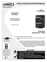
FLOOR PROTECTION – Advantage II-T C FS
(For USA and Can-
ada) This appliance
requires 3/8" (10
mm) minimum non-
combustible floor
protection designed
for solid fuel burning
appliances having a
thermal conductivity
of k = .84 BTU in/ft
or equivalent. If the
floor protection is to
be stone, tile, brick,
etc., it must be mor-
tared or grouted to
form a continuous
non-combustible sur-
face (See Using Alternate Material As Floor Protector below).
If a chimney connector extends horizontally over the floor,
protection must cover the floor under the connector and at
least 2" (51 mm) to either side. The floor protector must fully
cover the area beneath the appliance and extend 6” to the
front, 6” to the sides, and up to 6” from the back (see illustra-
tion above and following note).
*Note: When installed at clearances less than 6”, the floor
protection is only required to extend to the wall.
FLOOR PROTECTION / HEARTH EXTENSION USING AL-
TERNATE MATERIAL AS FLOOR PROTECTOR
(also see
Floor Protection above for freestanding models and Hearth
Requirements, page 8 for the insert model)
The hearth pad or alternate material used as a floor/hearth
protector must be constructed of a durable noncombustible
material having an equal or better thermal conductivity value
(lower k value) of k = .84 BTU / IN FT
2
HR °F or a thermal
resistance that equals or exceeds r = 1.19 HR °F FT
2
IN/BTU
with a minimum thickness of 3/8”. With these values, determine
the minimum thickness of the alternate material required using
the formula(s) and the table shown here (see chart - Approved
Alternate Materials for Floor/Hearth Protection).
Note: Any noncombustible material having a minimum thickness
of 3/8” (10 mm) whose k value is less than .84 or whose r value is
more than 1.19 is acceptable. If the alternate material used has a
higher k value or lower r value will require a greater thickness of
the material used. In some cases, if the k value is less or the r
value higher, a thinner material may be used.
Methods of determining floor protection equivalents:
To determine the thickness required for the alternate material
when either the k value or r value is known, use either the k
formula or r formula:
Example: Durock Cement
is to be used for the floor protec-
tion. How thick must this material be? The following formulas
give the means of determining minimum thickness required.
T
M
= minimum thickness required for alternate material
k
M
= k value per inch of alternate material
T
L
= minimum thickness of listed material
r
M
= r value per inch of alternate material
Using the k formula
:
Minimum k-value (per Inch) Specified min.
thickness of = of alternate material
x thickness
alternate k-value (per inch) of listed
material of listed material material
T
M
(inches) = k
M
x T
L
.84
T
M
(inches) = 1.92 x .375 (3/8”)
.84
Answer using k: 2.29 x 0.375” = 0.858 = ~7/8”
7/8” thickness (minimum) Durock Cement will be required.
Using the r formula
:
T
M
(inches) = 1.19 x T
L
r
M
T
M
(inches) = 1.19 x 375 (3/8”)
.52
Answer using r: 2.29 x 0. 375” = 0.858 = ~7/8”
7/8” thickness (minimum) Durock Cement will be required.
At times it is important to know what combination of materials are
acceptable for use as floor protection. The “R values” are used to
determine acceptable combinations of materials because “R val-
ues” are additive where r and k values are not.
“R value” = 1
= r x thickness of material used
k
Example: Given that the required “R value” for a suitable floor pro-
tector used must be equal to or greater than “R” = r x T
L
= 1.19 x
.375” = .45.
Approved Alternate Materials for
Floor/Hearth Protection (**)
Alternative
Materials ↓
Thermal Values * Minimum
Thickness
k (per inch) r (per inch) T
M
Kaowool M Board .47 2.13 * 3/8”
Micore 160
.35 2.86 * 3/8”
Micore 300
.46 2.18 * 3/8”
Durock Cement
1.92 .52 7/8”
Hardibacker
1.95 .51 7/8”
Hardibacker 500
2.30 .44 1 1/8”
Cultered Stone
Hearthstone
2.82 .35 1 5/8”
Wonderboard 3.23 0.31 1 1/2”
Face brick 9.00 0.11 4 1/8”
Common brick 5.00 0.20
2 1/4”
Cement mortar 5.00 0.20 2 1/4”
Ceramic tile 12.5 .08
5 5/8”
Marble
~20.0 ~.05
9”
Note: To convert inches to millimeters divide by .03937.
* After minimum thickness is calculated, the thickness can be no
less than 3/8” (.375” / 10mm).
(**) If the floor protector to be used is a noncombustible material and is
NOT listed on the chart above, the manufacturer of the material must
provide either the listed k-value per inch or r-value per inch and the
minimum acceptable thickness will need to be calculated per instruc-
tions on this page.
Top View
6”
153 mm
6”
(153mm)
min.
Listed Material
Thermal Values
Specified
Minimum
Thickness
k (per inch) r (per inch) T
L
Listed Material →
.84 1.19 3/8” (.375)
6”
153 mm
6”
(153mm)
min.
www.PelletKing.com

PLANNING YOUR INSTALLATION
Clearances to combustibles are determined from testing to applicable standards for allow-
able heat transfer. The clearances allowed as shown here, do not take into account opera-
tion or serviceability requirements.
PAGE 6
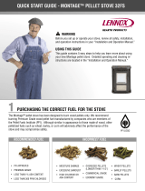
CLEARANCES
Advantage II-T C FS - Standard residential or manufac-
tured (mobile) home installation. These appliances re-
quire the following minimum clearances to combustibles:
MINIMUM CLEARANCES TO COMBUSTIBLES
Manufactured (Mobile) Home
or Residential Installation
Horizontal Flue – Di-
rectly Through Wall
Interior Vertical Flue
Advantage II-T C
FS
▪ Clearance to
Combustibles
inch / millimeter inch / millimeter
A - Sidewall to unit ♦6” / 153 mm ♦6” / 153 mm
B – Backwall to unit *2” / 50 mm 9” / 230 mm
C – Sidewall to unit
Corner
*2” / 50 mm *2” / 50 mm
D - Alcove to Fuel
Hopper
6” / 150 mm 6” / 150 mm
E – Max. Depth of
Alcove
•16” / 406 mm •16” / 406 mm
F – Flue to Wall n / a 3” / 77 mm
♦ Measured to fuel hopper
• Alcove Requirements – Minimum Height 50” / 127 cm
Minimum Width 36” / 966 mm
Maximum. Depth 16" / 406 mm
Minimum clearances specified may not allow for
ease of operation and maintenance (please take
this in to account when planning the installation).
If installed to the minimum clearances, removal of
the appliance may be necessary for servicing.
• Recommended clearance zone from the front of
the appliance to combustibles is 4 feet minimum.
* The certified back wall clearance as shown on the
listing label is 1" (see Safety / Listing Label) but for
proper hopper lid operation in corner and parallel
installations a 2" clearance is required.
Alcove - Advantage II-T C FS
Parallel Wall - Advantage II-T C FS
Corner - Advantage II-T C FS
F
*B
A
C
F
C
F
*B
E
D D
www.PelletKing.com

PLANNING YOUR INSTALLATION
PAGE 7
MASONRY AND FACTORY BUILT FIREPLACES
The model Advantage II-T C INS is approved for installa-
tion into a solid fuel burning fireplace, either a masonry
fireplace (built to UBC 37 or ULC S628 standards) or an
approved factory-built / zero clearance fireplace (built to
UL 127 or ULC S610 standards). (see pages 19 through
20 for additional information on venting).
Dimensions Into a Fireplace
Height 20 1/4” / 515 mm
Width 30 1/4” / 768 mm
Depth w/Tee 18 3/8” / 467 mm
Depth–DV thru Masonry Wall 12 1/2” / 318 mm
Recommended clearance zone from the front of the ap-
pliance to combustibles is 4 feet minimum.
CAUTION: The fireplace in which the Advantage II-T C
INS is to be installed must be thoroughly cleaned if it
has been used to burn wood or synthetic logs. Have the
chimney and all inside surfaces of the fireplace brushed
and vacuumed so that no soot, embers, or loose com-
bustion deposits can be drawn into the heat circulation
blower and blown into the living area. If any portion of
the chimney system shows signs of structural or me-
chanical weaknesses, such as: cracks, leaky joints, cor-
roded or warped surfaces, the faulty portion must be
repaired or replaced prior to installing this appliance.
IMPORTANT: When installing model Advantage II-T C
INS into a factory built fireplace or heatform, the air flow
within and around the fireplace shall not be altered by the
installation of the insert (i.e. DO NOT BLOCK louvers or
cooling air inlet or outlet ports, circulating air chambers in
a steel fireplace liner or metal heat circulator). The factory
built firebox must accept the insert without modification
other than removing bolted or screwed together pieces
such as smoke shelf / deflectors, ash lips, screen or door
tracks and damper assemblies. Any fireplace component,
which is removed, must be retained so they can be rein-
stalled to restore the fireplace to its original operating con-
dition. The removal of any part must not alter the integrity
of the outer shell of the pre-engineered fireplace cabinet
in any way. A Warning Label (provided with appliance)
must be installed in the fireplace firebox so that it shall be
visible upon removal of the fireplace insert (see Fireplace
Warning Label, below). Use RTV high Temperature Sili-
cone as an adhesive to affix the warning label.
Fireplace Warning Label
Provided in accessory package (insert only)
THIS FIREPLACE HAS BEEN ALTERED TO AC-
COMMODATE A FIREPLACE INSERT AND SHOULD
BE INSPECTED BY A QUALIFIED PERSON PRIOR
TO RE-USE AS A CONVENTIONAL FIREPLACE.
HEARTH / FLOOR PROTECTION - Advantage II-T C
INS
In the USA and Canada, the area below and directly in
front of the Advantage II-T C INS must be an approved
fireplace hearth or protected by a non-combustible
hearth / floor protector with a minimum thickness of 3/8”
which has a thermal conductivity of k (per inch) = .84 or
lower value (better thermal protection) or resistance of r
(per inch) = 1.19 or higher value. See Floor Protection /
Hearth Extension Using Alternate Material as Floor Pro-
tector on page 5 which explains minimum thermal pro-
tection requirements.
The protected area must extend 6” to the front of the face
of the Advantage II-T C INS.
MINIMUM CLEARANCES TO COMBUSTIBLES
Masonry and Factory Built Fireplaces
inches / millimeters
A - Insert to side wall 6 “ / 150 mm
B - Insert to side trim 1” / 25 mm
C - Hearth extension 6” / 150 mm
D - Insert to mantel 18” / 457 mm
E - Insert to top trim 1” / 25 mm
Front View
Side View
DE
B
A
D
E
C
www.PelletKing.com

PLANNING YOUR INSTALLATION
PAGE 8
MANUFACTURED (MOBILE) HOME INSTAL-
LATION
Freestanding Model – Advantage II-T C FS
In addition to the standard installation instructions,
the following instructions may be required by lo-
cal, state or federal building codes:
• Stove must be permanently bolted to the floor.
• An outside air inlet must be provided for com-
bustion and be unrestricted while unit is in use.
Use a galvanized or stainless steel pipe for the
duct (the outside air inlet on the stove is 1 5/8"
diameter).
• Stove must be permanently electrically
grounded to the steel chassis of the home. The
location selected for ground attachment to the
stove must be dedicated for this purpose.
• See pages 13 through 18 for additional informa-
tion on venting requirements.
• Do not install appliance in a sleeping room.
• The structural integrity of the manufactured
home floor, walls, ceiling and roof must be
maintained.
NOTE: The grounding of this product, at installa-
tion, must comply with NFPA-70 stan-
dards, CSA C22.1 in Canada, as well as
any local codes.
Model – Advantage II-T C FS
Pedestal Air Inlet
MANUFACTURED (MOBILE) HOME EXHAUST VENT PIPE
INSTALLATION GUIDELINES
Use only “PL” pellet vent pipe listed to UL 641 and ULC
S609. The pipe should extend at least 3 feet above the part
of the roof through which it passes. The top of the pipe
should be at least 2 feet above the highest required elevation
of any part of the manufactured (mobile) home within 10 feet
of the pipe (see page 14, Manufactured [Mobile] Home
Chimney Height Requirements).
If the exhaust vent exits the manufactured (mobile) home at a
location other than the roof, and exits at a point 7 feet or less
above the ground level on which the manufactured (mobile)
home is position a guard or method of enclosing the pipe
shall be provided at the point of exit for a height of up to 7
feet. The openings, if any, in this guard shall not allow a 3/4”
rod to pass through. A 1/2” rod could pass through but should
not be able to touch the pipe when inserted through the open-
ing a distance of 4 inches.
24 ¾”
12 ½”
6 7/8”
25”
Outside Air Inlet
1 5/8" diameter
Bolt
Bolt
Floor Protector
Steel Chassis
Ground
To Chassis
Floor
www.PelletKing.com

INSTALLATION
PAGE 9
REMOVING APPLIANCE FROM PALLET
1. After removing the packaging from the stove, lift the
hopper lid, and remove all pre-packaged items that
were shipped in the hopper. Next, open the stove
door and remove all pre-packaged items.
2. Using a 9/16” socket or open end wrench, remove
the bolts which secure stove to pallet. The bolts are
located on the underside of the wooden pallet.
Underside of Pallet
Remove the two bolts from underneath the pallet.
NOTE: Bolts may be used in manufactured (mobile)
home installation to permanently secure stove to floor
(see previous page).
ASH PAN COVER ASSEMBLY
Remove the ash pan cover trim from hopper. Remove
polyfoam wrapping and press into place as shown in il-
lustration below. The ash pan cover trim has two mag-
nets attached which will secure it in place.
Ash Pan Cover
INSTALLING PEDESTAL TO BODY
If your stove is a freestanding model, secure the pedes-
tal to the stove body as follows:
1. Remove the pedestal from the box and place it be-
side the stove body.
2. Lift the stove onto the pedestal base.
3. Install the three bolts and washers provided through
the holes in the mounting flange of the pedestal and
into the threaded pressed nuts in the stove bottom.
4. Tighten the fasteners using a socket or wrench.
Pedestal – Top View
Attach stove to pedestal by inserting three bolts
(provided with pedestal kit)
Install
three bolts
www.PelletKing.com

INSTALLATION
PAGE 10
INSTALLATION CHECK LIST
It is strongly recommended that you have an authorized
Lennox Hearth Products dealer install your stove. If you
install your stove yourself, you should review your instal-
lation plan with an authorized Lennox Hearth Products
dealer. Improper installation may void your warranty.
Check list:
Check off each item as you proceed with the installation
process.
Read the ENTIRE stove installation section first
Read the Insert or Freestanding section (whichever
applies).
Determine the appropriate measurements and loca-
tions for your installation.
Follow the general installation directions under Stove
Installation and the installation section appropriate to
your stove.
Be sure to pre-fit all items before you install, fasten,
or set up the stove permanently.
Prior to lighting your stove:
Review the Important Warnings section (page 2).
Review Fuel Specifications (page 25).
Review and follow instructions in the Care and Op-
eration Section (pages 21 to 25).
Plug power cord connector into corresponding con-
nector on the back of appliance (see illustrations on
page 12 showing connector locations).
Note
: Advantage II-T C INS – Route power cord be-
hind side surround panel.
After you have begun operation of your stove:
Review the routine cleaning / maintenance informa-
tion.
Enjoy the warmth from your new Lennox Hearth
Products pellet stove!
Advantage II-T C Insert
It is important to level the appliance. In some installa-
tions such as a recessed firebox floor (if the existing fire-
place floor is lower than the hearth), install the 2 leveling
bolts (3/8-16 x 3 1/2” long) into the 2 threaded holes at
the rear base of the Advantage II-T C INS. Adjust bolts
until appliance is level.
www.PelletKing.com

INSTALLATION
PAGE 11
INSTALLING SURROUND ASSEMBLY - Advantage II-T
C INS (to be done after venting system is installed)
The surround kit (purchased separately) comes with a set
of metal panels that enclose the fireplace opening when
fitted together. Put the surround assembly together accord-
ing to the following instructions (ref. see illustration below).
1. Remove panels from package.
2. Verify that you have all three panels and a package with
“pop” rivets and #8 self-tapping screws. If you do not have
a “pop” rivet tool, you should arrange to buy or borrow one
for this installation.
3. Set the stove on the hearth so that the rear of the stove is
accessible to complete all pipe connections.
4. Verify that the hopper cover is all the way to the front and
open as high as your fireplace opening will allow. Secure
the hopper cover with at least two #8 screws on all three
sides. Tip: Spreading the side panels slightly may be nec-
essary to complete this step.
5. Place four rivets and your “pop” rivet tool beside the stove
and line up the right side panel (with control door) with the
holes in the side of the stove. (When the side panel is
properly installed, the hinge flange will be to the rear of the
stove.) Attach the panel to the stove with four “pop” rivets.
6. Secure the left side surround panel to the stove using the
procedure described in step #5.
7. Before proceeding further, check pipe connections to en-
sure that all joints are sealed with high-temperature RTV
silicone and properly secured. Refer to detailed venting in-
structions on pages 16, 19 and 20.
8. The stove may now be pushed into the fireplace cavity to
within 1 1/2” of the face of the fireplace.
9. Set the top surround panel in place over the two side pan-
els. Carefully slide the panel downward into the “U” clips
attached to the back of the Advantage II-T C INS. Tip: Be
careful to align the notched cutouts in the top surround
panel with the stove side panels. Adjust side to side if nec-
essary to align with the surround side panels.
10. Unwrap the control board carefully without touching
any electrical components. Holding the sides of the
control board, lower the bottom edge into the slot in
the bottom of the control door opening Install the
control board onto the right side panel (with door) us-
ing the #8 hex head screw provided.
11. Connect the wiring harness from the Advantage II-T C INS
into corresponding connector on control board.
12. Check the Advantage II-T C INS placement in the
fireplace. To reposition, open the door and make any
needed adjustment by pulling forward and then push-
ing sideways. Once the unit has been centered to
your satisfaction, close the door and push the Advan-
tage II-T C INS back into place so the surround is
flush with the face of the hearth. Tip: Before com-
pleting this step, verify that the control board will not
hit the edge of the fireplace opening.
If using the optional gold surround trim, remove the trim
from its packaging and place the piece with the two mi-
tered ends along the top panel. Place the two remaining
side pieces on the surround so that the mitered ends
align. Cut the non-mitered ends of the shroud trim with
scissors, if necessary.
In factory built and masonry fireplaces, a means
must be provided to prevent room air passage to the
chimney cavity of the fireplace. This may be accom-
plished by sealing the damper area around the chim-
ney liner or pipe.
Top Surround Panel
Left Hinged
Surround Panel
Right Hinged
Surround Panel
Optional Trim Optional Trim
www.PelletKing.com

INSTALLATION
PAGE 12
THERMOSTAT INSTALLATION:
NOTE: Always Disconnect Power Before Performing
The Thermostat Installation.
A 24 volt wall thermostat and 20 feet of 18-gage thermo-
stat wire is included in your stove’s accessory package.
It is recommended that the thermostat and thermostat
wire be installed by an authorized Lennox Hearth Prod-
ucts dealer.
Installation Steps:
1. Unplug stove power cord from the wall outlet.
2. Locate the thermostat terminal block on the back of
the stove.
3. Loosen the two terminal screws on the terminal block
and remove jumper.
4. Connect the two wires from your thermostat to the
terminals (one per terminal). Ensure that the purple
wires from the harness remain connected to the ter-
minal block and tighten the terminal screws. Make
sure the wires are firmly connected to the thermo-
stat.
5. Plug in the stove and you are ready to operate with
your thermostat!
IMPORTANT: IF THE WALL THERMOSTAT PRO-
VIDED IS NOT
USED, THE JUMPER IS REQUIRED
FOR THE STOVE TO OPERATE
Rear View of Advantage II-T C FS
Back of Stove
Thermostat Jumper
Thermostat
Terminal
Block
www.PelletKing.com

INSTALLATION
PAGE 13
VENTING REQUIREMENTS
It is recommended that only an authorized dealer install
your pellet stove. The specified installation requirements
must be followed to ensure conformity with both the
safety listing of the appliance and local building codes.
All clearances, installation instructions and precautions
specified by the vent manufacturer must be followed.
Selecting a Location (Freestanding Models) - Review
the appliance clearance requirements before installing
the venting system (see page 6). Position the appliance
far enough away from walls to allow adequate room for
servicing. Choose the appliance location with the least
amount of interference with the house framing, plumbing,
wiring, etc.
Preferred Vent Configuration - For the best perform-
ance, we recommend a vent run design which runs verti-
cally and terminates above the roofline. This design will
allow natural draft to improve the flow of flue gases and
will aid in combustion and stove performance.
Type of Pipe - This stove requires type “PL” vent pipe
(pellet vent pipe, sometimes referred to as “L-Vent pellet
vent”), listed to UL 641 or ULC S609. Connect the pellet
vent pipe or the “tee” to the flue collar using a minimum
of three screws and seal as specified in “Pipe / Liner
Joint Requirements” on this page. Do not use class B gas
chimney or single wall chimney as a substitute.
Size of Pipe - These pellet appliances are approved for
use with the following vent sizes: 3” (75mm) standard, or
4” (100mm), see page 15 - for determining correct size
vent). When 4” pipe is used: for horizontal vent installa-
tions use a 3” (75mm) to 4” (100mm) adapter - available
from vent manufacturer. For vertical installations use a
3” (75mm) to 4” (100mm) “tee” - available from vent
manufacturer.
Note: If installation requires in excess of 11 feet (3 1/3
meter) of pipe, it is recommended that 4” (100 mm) pipe
be used.
Offsets - In every installation, a single or double clean-
out “tee” is recommended for every ninety-degree offset
(this tee will help collect ash residue and will allow for
routine cleaning without the need to disconnect sections
of pipe). Note: Offsets and horizontal runs accumulate
fly ash and soot which reduces the exhaust flow and per-
formance of the stove.
Total Offsets in venting system should not exceed 270°
total in direction change.
Horizontal Runs - The maximum total horizontal run
must not exceed 10 feet (3.1 meters).
Horizontal run of pipe requires 1/4” (7 mm) rise per foot.
Pipe Clearances / Requirements - See pipe manufac-
turers instructions for installation of venting components
and clearances. Follow pipe manufacturers installation
precautions for passing pipe through a combustible wall
or ceiling (i.e. use an approved thimble). Note: Pellet
vent pipe requires 3” (75mm) clearance from outside of
pipe unless otherwise specified by vent manufacturer -
all diameters: 3” (75mm) and 4” (100mm). A support
bracket must be installed every 4’ (1.2m) of pellet vent
pipe on the exterior wall of the house unless otherwise
specified by vent manufacturer.
Pipe / Liner Joint Requirements - All pipe joints must
be secured with a minimum of 3 screws. ALL horizontal
joints must be sealed gas tight (air tight, sealed connec-
tion). Use RTV high temperature silicone or Interam to
provide a complete seal at the flue collar and on all
joints.
Connection to Masonry Chimney through a Wall
(Freestanding Models) - Be sure to verify the construc-
tion of a masonry chimney, as it may have combustible
framing.
Approved liner when relining Masonry or Factory
Built Fireplaces is 2100HT (degree F.) liner listed to
UL 1777 or ULC S635.
Connection to an Existing Class A Chimney (Free-
standing Models) - A chimney adapter can be used to
make the connection from 3” (75mm) or 4” (100mm) pel-
let vent pipe (listed to UL 641 or ULC S609) to existing
UL chimney system. Verify with the pipe manufacturer
that your pipe brands will interconnect.
Horizontal-Vent Installations - On all horizontal-vent
installations (short, horizontal runs with no vertical pipe);
care should be taken when choosing a location for termi-
nating the vent. It is not recommended to directly vent
the exhaust on the prevailing wind side of the house. It is
recommended that when an appliance is vented directly
through a wall, a minimum of 8’ (2.5m) of vertical pipe
should be installed to create some natural draft. This will
reduce the possibility of smoke or odor entering the
dwelling during appliance shutdown or loss of power.
www.PelletKing.com

INSTALLATION
PAGE 14
VENT TERMINATION
Do not terminate vent in an enclosed or semi-enclosed
area such as: carports, garage, attic, crawl space, under
a deck, porch, narrow walkway, closely fenced area, or
any location that can build up a concentration of fumes
such as a stairwell, covered breezeway etc.
Vent surfaces can get hot enough to cause burns if
touched. Adults should supervise children when they are
in the area of a hot stove. Non-combustible shielding or
guards may be required.
Termination Cap: The termination of the outside chim-
ney of the pellet stove shall be located in accordance
with the following:
A. Higher than 3’ (.92m) above any forced air inlet (air
conditioner, etc.) located within 10’ (3m).
B. Not less than 4’ (1.2m) below, 4’ (1.2m) horizontally
from or 1’ (3.1m) above any gravity air inlet (door,
window, etc.) which flue gases could re-enter the
dwelling.
C. Not less than 2’ (.6m) from combustible materials
such as an adjacent buildings, fences, protruding
parts of the structure, roof overhang, plants and
shrubs, etc. and not less than 7’ (2.1m) above grade
when located adjacent to the public sidewalks (ac-
cess). The final termination of the exhaust system
must be configured so that flue gases do not jeop-
ardize the safety of people passing by, overheat
combustible portions of nearby structures or enter
the dwelling.
D. Not less than 3’ (.92m) below an eave (maximum
overhang of 3’ (.92m) or any construction that pro-
jects more than 2” (51mm) from the plane of the wall.
E. The distance from the bottom of termination to grade
is 12” (305mm) minimum. This is conditional upon
plants and nature of grade surface: Be careful to
choose a location for the vent termination which
does not expose people or shrubs to high heat from
the exhaust gases. The exhaust gases are not hot
enough to ignite grass, plants and shrubs located in
the vicinity of the termination although they should
be a minimum of 3’ (.92m) away. The grade surface
under the termination must not be a lawn.
F. Since sparks may escape from the exhaust pipe of
any stove, use caution when positioning the vent
pipe. Refer to pipe manufacturer’s instructions when
installing and terminating the exhaust. The vent pipe
should be horizontal and never run the pipe in a
downward direction (recommend a 1/4” (7mm) rise
per foot horizontal).
Notes:
• It is not recommended to terminate exhaust vent on
the prevailing wind side of the house.
• It is not recommended using a termination cap
with a screen (fly ash can collect in a screen re-
sulting in blockage).
Site Built Residential Home
Chimney Height Requirements
The vent termination height required is - USA, 1-foot
minimum; Canada 3-feet minimum above the roof pene-
tration point as illustrated below (Ref. USA - National
Standard, NFPA 211, Clause 7-4.1 and Canada National
Standard CSA B365-01, Clause 5.6). Check with your
local building official for additional requirements for your
area.
Manufactured (Mobile) Home
Chimney Height Requirements
The chimney must extend 3’ (.92m) above the level of
roof penetration and a minimum of 2’ (.61m) higher than
any roof surface within 10’ (3m) (see below). Check with
your local building officials for additional requirements for
your area.
To pass inspection in nearly any jurisdiction, the chimney
must meet both safety and exhaust flow requirements.
The (3’ by) 2’ by 10’ rule applies to both masonry and
factory built chimneys.
* Ref. NFPA 211 Clause 7 – 4.1.2, Vents installed with a
listed cap shall terminate in accordance with the terms
of the cap’s listings.
REQUIRES A LISTED
TERMINATI
O
N
C
AP *
TOP OF FLUE MUST BE 2’
HIGHER THAN ANY PART OF
ROOF WITHIN 10’ HORIZONTAL
TOP OF FLUE MUST BE 3’ HIGHER THAN
HI
G
HE
S
T P
O
INT
O
F R
OO
F PENETRATI
O
N
TERMINATION
CAP MUST BE
LISTED TO UL
641 AND ULC
S609 *
TERMINATION HEIGHT IS
MEASURED ABOVE THE
HIGHEST POINT WHERE
IT PASSES THROUGH
THE ROOF SURFACE.
USA 1 Foot Minimum
CANADA 3 Feet Minimum
www.PelletKing.com

INSTALLATION
PAGE 15
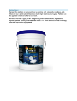
DETERMINING SIZE OF PIPE TO INSTALL
To determine what diameter pipe to use in an installation (3” or 4”), first find the “equivalent pipe length” using the follow-
ing guidelines, then plot this figure and the altitude on the chart.
Fill out the installation chart, and calculate your total equivalent pipe length. After you have the total equivalent pipe
length, use the Pipe Selection Chart below to determine if your installation requires 3” or 4” exhaust pipe
.
INSTALLATION CHART
Type of
Pipe
# of Elbows
or Feet of
pipe
Equivalent
Feet
Total
Equivalent
Feet
90
o
Elbows /
Tee (A & G)
x 5 Ft. (1.5m)
45
o
Elbows (C)
x 3 Ft. (1m)
Horizontal
(B & F)
x 1 Ft. (.3m)
Vertical
(E)
x .5 Ft.
(.15m)
A- 90 Degree Elbow E- 8’ Vertical Pipe
B- 1’ Horizontal Pipe F- 2’ Horizontal Pipe
C- 45 Degree Elbow G- 90 Degree Tee
D- Standoff Braces
H- Wall Thimble
NOTE: All equivalent pipe styles shown below are stan-
dard for all freestanding models.
SAMPLE INSTALLATION CHART
Type of
Pipe
# of Elbows
or Feet of
pipe
Equivalent
Feet
Total
Equivalent
Feet
90
o
Elbows /
Tee (A & G)
2 x 5 Ft. (1.5m) 10 (3m)
45
o
Elbows (C)
1 x 3 Ft. (1m) 3 (1m)
Horizontal
(B & F)
3 x 1 Ft. (.3m) 3 (1m)
Vertical
(E)
8 x .5 Ft. (.15m) 4 (1.2m)
Total = 20
PIPE SELECTION CHART
0 1 2 3 4 5 6 7 8 9 10
Altitude x 1000 Feet
4 “ Diameter Only
3 or 4”
Diamete
r
30
20
10
0
Equivalent Pipe Length (Feet)
www.PelletKing.com

INSTALLATION
Note: Greater back clearance will improve the ease of serviceability of the stove.
PAGE 16
INSTALLING YOUR FREESTANDING PELLET STOVE
Standard Horizontal Vent Installation
All PL Venting Components must be listed to UL 641
or ULC S609
1. Locate the proper position for the listed type “PL” wall
thimble. Avoid cutting wall studs when installing your
pipe. Use a saber saw or keyhole saw to cut the
proper diameter hole through the wall to accommo-
date the wall thimble. Use extreme caution to avoid
cutting into power lines within the wall of the home.
The hole size will depend on the brand of pellet vent
that you are using. Install the wall thimble in the hole.
2. ALL INTERLOCKING PIPE CONNECTIONS WITH-IN
THE ROOM MUST BE SEALED WITH HIGH TEM-
PERATURE RTV AND SECURED WITH A MINIMUM
OF 3 FASTENERS PER CONNECTION. Position the
stove approximately 12” (305 mm) from the wall on
the floor pad. Push the “PL” pipe through the wall
thimble. Squeeze a bead of high temperature silicone
(RTV) sealer around the end of the machined portion
of the 3” (76mm) pipe connector on the back of the
stove. Firmly push on a section of “PL” pipe until in-
ner pipe liner pushes into the bead of RTV sealer.
3. Push the stove with pipe attached towards the wall
(the pipe will go through the wall thimble). Do not
position the back of the stove closer than 2” (51mm)
from the wall (see clearances, page 6). Note:
Greater back wall clearance will improve the ease of
serviceability of the stove.
4. Install listed type “PL” 45 degree elbow with optional
rodent screen or cap (recommended) on outside end
of pipe. The rodent screen should be no less than
1/2” (13 mm) mesh and may clog with soot and ash if
left unattended during the burn season.
NOTE: The end of the exhaust pipe must extend a
minimum of 12” (305 mm) from the outside of the
building.
5. If the installation includes a source of outside com-
bustion air; cut a separate hole through the wall for
the fresh air tube. Use a galvanized or stainless steel
pipe for the duct. The minimum size for the duct
shall be not less than 50% of the cross sectional flue
area. Connect outside air pipe to air inlet on stove.
This tube must be terminated with a 45 degree elbow
or hood.
NOTES:
Combustion air may also be drawn from a vented crawl
space under the home.
All joints for connector pipe are required to be fastened
with at least three screws. If vented horizontally, joints
shall be made gas-tight (air tight, sealed connection) in a
manner as specified on this page (see instruction #2).
Install vent at clearances specified by the vent manufac-
turer.
Inlet Air
Port
Metal
Fresh Air
Pipe
45 Degree Elbow Joint
For Fresh Air Pipe
Hole Through the
Wall for the Thimble
Pipe Connector
on Stove
Wall Thimble
Use RTV High
Temp Silicone
Hole
Through
the Wall for
the Fresh
Air Pipe
Use RTV High
Temp Silicone
45° Elbow
Horizontal l
Pipe
Use RTV High
Temp Silicone
Wall Thimble
www.PelletKing.com

INSTALLATION
Standard Horizontal Installation Configurations
PAGE 17
Advantage II-T C FS*
Corner Through the Wall
Advantage II-T C FS
Horizontal Vent Through the Wall
Top View Illustration
3” (75 mm) Minimum clearance
between wall and pipe. If you vent
to the furthest wall, the vent pipe
must maintain a 3” clearance par-
allel to the other wall.
6” (152 mm)
Minimum
Horizontal Vent Through the Wall
Side View Illustration
2” (51 mm)
Minimum
45 Degree Elbow
12” (305 mm)
Minimum
12” (305 mm)
from Ground or
Other Surface
Hearth Pad / Floor Protector
2”
2”
Wall
www.PelletKing.com

INSTALLATION
Standard Vertical Installation Configurations - Model: Advantage II-T C FS - These freestanding models may be con-
nected to an existing unused flue or by installing type “PL” vent pipe (listed to UL 641 & ULC S609). If a liner is run all the way
to the top of the existing chimney, the existing flue should be sealed with a steel plate. Start a vertical run with a Tee at the
back of the stove. Other options are illustrated below. Note: See page 13 for Vent Termination Requirements.
PAGE 18
Exterior Vertical Vent
Vertical Vent Into A Masonry Flue
Preferred Installation – Vertical Vent Through the Roof
This venting configuration allows for the best stove
performance. The vertical pipe promotes natural draft
and with the chimney inside the dwelling, the flue
gases stay warm, thus rising at a consistent rate.
Interior Vertical Vent into an
Existing Class A Chimney
Wall Straps Re-
quired Every 4 ft.
Minimum
Optional Complete
Liner and Listed
Termination Cap
Optional Clean-
Out Access
Door
Listed Rain Cap
See Page 14 Vent
Termination Re-
quirements
Clean-Out
Tee
3”
Min
.
Existing
Chimney
Pipe
Pipe Increaser
3”
Min.
Extend Pipe to
the Top if Exist-
ing Chimney is
Corroded or
Damaged
www.PelletKing.com

INSTALLATION - ADVANTAGE II-T C INS
IMPORTANT- Make sure the chimney and firebox are clean and free of soot and ashes before installation begins. Fail-
ure to do so may result in the transfer of soot into the room by way of the Room Air Blower.
PAGE 19
Positive Flue Connection without a Full Reline
(not allowed in Canada)
VENT TERMINATION WHEN LINER IS USED.
A section of pellet vent pipe (listed to UL 641 or ULC S609) is required
at the top where exposed to the elements (see illustration below).
This pellet insert may be installed into a ma-
sonry fireplace (built to UBC 37 or ULC S628
standards) or a factory built fireplace (built to
UL 127 or ULC S610 standards) as illus-
trated on this page. When installing into a
masonry chimney, it is recommended that
the exhaust vent be extended to the top of
the chimney as shown on the following page.
However, if the vent pipe does not extend to
the top of the chimney, the vent must extend
a minimum of 18” above the damper. You
must seal the damper area so that the air /
exhaust in the chimney cannot communicate
with the air in the fireplace firebox (this is a
positive flue connection. See the following
instructions for one method of sealing flue).
(USA & Canada) Direct Connection / Posi-
tive Flue Connection
In Canada, this appliance requires a full re-
line when installing into a masonry fireplace.
In the USA, as a minimum the vent connec-
tor from the insert flue outlet must extend a
minimum of 18” above the damper and the
damper area must be sealed to prevent dilu-
tion air from entering the chimney which will
affect proper drafting of appliance.
See the following instructions for acceptable
methods for sealing chimney throat.
Approved Methods of Achieving a Positive
Flue Connection - A qualified installer should
evaluate the existing fireplace to determine
the best method for achieving a positive flue
connection between the vent pipe or liner
and the chimney. The most common method
for achieving a positive flue connection in
masonry fireplaces is to secure a seal-off
plate (i.e. 22-gage sheet steel) in the fire-
place throat using masonry screws. Other
acceptable methods include packing non-
combustible material (i.e. rockwool) around
the vent pipe or using a flue adapter. What-
ever “seal off” method is used must effec-
tively seal the area to prevent room air pas-
sage to the chimney cavity of the fireplace.
The vent pipe must
extend a minimum o
f
18” above the damper.
The existing chimne
y
must not be corroded o
r
damaged in any way.
18” Min.
(457 mm) to
Mantel
1” Min.
(25 mm)
to Trim
♦ 6” Min.
Floor
Protection
A
non-combustible seal is
required at the dampe
r
area (to prevent dilu-
tion/air from entering the
chimney. See Positive
Flue Connection on this
page.
Optional Clean Out Access
Door
Clean Out
Tee
Mantel
Pellet Vent Cap - Listed to
UL 641 & ULC S609
1' Section of PL
Vent - Listed to
UL 641 &
ULC S609
3" or 4" liner (listed to
UL 1777 or ULC S635
)
Chase Cover
Positive Flue Connec-
tion into a Masonr
y
Fireplace without a Full
Reline – Advantage II-
T
C INS
The Advantage II-T C
INS does not require a
full reline (in USA only)
when installing into a
masonry fireplace, how-
ever, it is recommended
to ensure proper drafting
of the appliance. The
vent connector from the
insert must extend a
minimum of 18” above
the damper and the
damper area must be
sealed to prevent dilution
air from entering the
chimney which will affec
t
proper drafting of appli-
ance
(USA Only) Venting Into an Existing Chimney
www.PelletKing.com

INSTALLATION
INSTALLING ADVANTAGE II-T C INS (CONTINUED)
PAGE 20
Full Chimney Reline
Recommended for All
Chimney Installations
Horizontal Vent Through Masonry Chimney Structure
.
♦ USA & Canada – Requires an approved noncom-
bustible hearth or floor protector, 3/8” / (10 mm)
millboard or equivalent (k = .84, r = 1.19) to ex-
tend 6” / 150 m19-20m to the front of the glass
door.
Do not block opening at front of insert (below
door).
Seal Chimney top with steel
plate and/or pipe support
Listed Rain Cap
A
pproved Liner for Factor
y
Built (ZC) Fireplaces and
Masonry Fireplaces is
2100HT (degree F.) line
r
listed to UL 1777 or ULC
S635. The liner must be se-
curely attached to the insert
flue collar and the chimne
y
top.
18” Min.
(457 mm)
to Mantel
1” Min.
(25 mm)
to Trim
♦ 6” Min. Floor
Protection
Optional Posi-
tive Flue
Connection
Clean
Out Tee
USA – The insert ma
y
be installed as a Hori-
zontal Vent (through
chimney structure) in
Masonry Fireplaces i
f
local code permits.
IN CANADA – Installing as a Horizon-
tal Vent is NOT allowed. The fireplace
chimney must be fully lined.
18” Min.
(457 mm)
to Mantel
♦ 6” Min. Floor
Protection
1” Min.
(25 mm)
to Trim
Mantel
Mantel
IMPORTANT NOTES:
A
flexible corrugated chimne
y
liner has much greater resis-
tance to the flow of flue gases
than does a rigid liner. For this
reason we recommend that a
larger, 4” liner be used on ver-
tical runs exceeding 15 feet o
r
that rigid venting be used as
illustrated on this page (see
Full Chimney Reline).
If a flexible corrugated chimney
liner is used, it must be fully
extended to eliminate any sag-
ging and to improve the ex-
haust flow.
www.PelletKing.com
/