LevelOne ProCon GSW-4896 User manual
- Category
- Network switches
- Type
- User manual

GSW-4896
48-Port TP with 4-Port shared SFP L2 SNMP Gigabit Switch
User Manual
Ver. 1.01-0711

ii
Table of Contents
Caution ................................................................................................................................ v
Electronic Emission Notices............................................................................................... v
1. Introduction.......................................................................................................... 2
1-1. Overview of the switch................................................................................................ 2
1-2. Checklist....................................................................................................................... 4
1-3. Features ........................................................................................................................ 4
1-4. View of the switch........................................................................................................ 6
1-4-1. User Interfaces on the Front Panel (Button, LEDs and Plugs) ............................................ 6
1-4-2. User Interfaces on the Rear Panel ....................................................................................... 7
1-5. View of the Optional Modules.................................................................................... 8
2. Installation............................................................................................................ 9
2-1. Starting the switch Up................................................................................................. 9
2-1-1. Hardware and Cable Installation ......................................................................................... 9
2-1-2. Installing Chassis to a 19-Inch Wiring Closet Rail.............................................................11
2-1-3. Cabling Requirements ........................................................................................................11
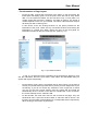
2-1-4. Configuring the Management Agent of the switch............................................................ 17
2-1-5. IP Address Assignment...................................................................................................... 21
2-2. Typical Applications.................................................................................................. 26
3. Operation of Web-based Management ............................................................. 28
3-1. System......................................................................................................................... 30
3-1-1. System Information........................................................................................................... 32
3-1-2. IP Configuration................................................................................................................ 34
3-1-3. Time Configuration ........................................................................................................... 37
3-1-4. Account Configuration ...................................................................................................... 40
3-1-5. Management Policy........................................................................................................... 42
3-2. Port Configuration .................................................................................................... 47
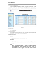
3-2-1.Port Status .......................................................................................................................... 47
3-2-2. Port Configuration............................................................................................................. 52
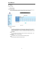
3-2-3. Simple Counter.................................................................................................................. 54
3-2-4. Detail Counter ................................................................................................................... 55
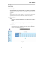
3-3. Storm .......................................................................................................................... 58
3-4. Mirror......................................................................................................................... 59
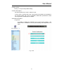
3-5. Filter ........................................................................................................................... 60
3-5-1. Bad Length ........................................................................................................................ 60
3-5-2. Unknown Encap. ............................................................................................................... 61
3-5-3. Unknown Ether-Type ........................................................................................................ 62
3-5-4. Unknown IP Protocol ........................................................................................................ 63
3-5-5. IPv4 Options...................................................................................................................... 64
3-5-6. Unknown Source ............................................................................................................... 65
3-6. QoS(Quality of Service) Configuration ................................................................... 66

iii
3-6-1. Priority .............................................................................................................................. 66
3-6-2. Policer ............................................................................................................................... 76
3-6-3. Shaper................................................................................................................................ 77
3-6-4. Flow .................................................................................................................................. 78
3-6-5. Police-Flow ....................................................................................................................... 85
3-6-6. Mark .................................................................................................................................. 86
3-6-7. Mark-enable ...................................................................................................................... 87
3-7. ACL............................................................................................................................. 88
3-7-1. ACL Mode......................................................................................................................... 88
3-7-2. ACL/VLAN Mapping ....................................................................................................... 89
3-7-3. ACL Rule........................................................................................................................... 90
3-8. ACL QoS Load........................................................................................................... 91
3-9. User Defined............................................................................................................... 92
3-10. SNMP Configuration............................................................................................... 93
3-11. IGMP Snooping ....................................................................................................... 99
3-12. Trunk ...................................................................................................................... 103
3-13. STP Configuration..................................................................................................110
3-13-1. STP Status ......................................................................................................................110
3-13-2. STP Configuration..........................................................................................................112
3-13-3. STP Port Configuration ..................................................................................................114
3-14. GVRP Configuration..............................................................................................117
3-15. 802.1X Configuration............................................................................................ 123
3-16. Alarm Configuration............................................................................................. 134
3-17. Configuration......................................................................................................... 137
3-17-2. Config File .................................................................................................................... 143
3-18. Diagnostics ............................................................................................................. 144
3-19. Loop Detection....................................................................................................... 147
3-20. TFTP Server........................................................................................................... 148
3-21. Log .......................................................................................................................... 149
3-22. Firmware Upgrade................................................................................................ 151
3-23. Max. Packet Length .............................................................................................. 152
3-24. MAC Table............................................................................................................. 153
3-25. VLAN...................................................................................................................... 159
3-25-1. VLAN Mode ................................................................................................................. 159
3-25-2. VLAN Group ................................................................................................................ 161
3-25-3. Port Protocol.................................................................................................................. 165
3-25-4. Port VID........................................................................................................................ 166
3-26. Reboot..................................................................................................................... 167
3-27. Logout..................................................................................................................... 168
4. Operation of CLI Management ....................................................................... 169
4-1. CLI Management .................................................................................................... 169

iv
4-1-1. Login ............................................................................................................................... 169
4-2. Commands of CLI................................................................................................... 171
4-2-1. Global Commands of CLI ............................................................................................... 172
4-2-2. Local Commands of CLI................................................................................................. 178
5. Maintenance ........................................................................................................ 274
5-1. Resolving No Link Condition ................................................................................. 274
5-2. Q&A ......................................................................................................................... 274
Appendix A Technical Specifications...................................................................... 275
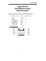
Appendix B Null Modem Cable Specifications...................................................... 279

v
Caution
Circuit devices are sensitive to static electricity, which can damage their delicate
electronics. Dry weather conditions or walking across a carpeted floor may cause you to
acquire a static electrical charge.
To protect your device, always:
• Touch the metal chassis of your computer to ground the static electrical charge before
you pick up the circuit device.
• Pick up the device by holding it on the left and right edges only.
Electronic Emission Notices
Federal Communications Commission (FCC) Statement
This equipment has been tested and found to comply with the limits for a class A
computing device pursuant to Subpart J of part 15 of FCC Rules, which are designed to
provide reasonable protection against such interference when operated in a commercial
environment.
European Community (CE) Electromagnetic Compatibility Directive
This equipment has been tested and found to comply with the protection requirements
of European Emission Standard EN55022/EN60555-2 and the Generic European Immunity
Standard EN50082-1.
EMC:
EN55022(1988)/CISPR-22(1985)
class A
EN60555-2(1995) class A
EN60555-3
IEC1000-4-2(1995) 4K V CD, 8KV, AD
IEC1000-4-3(1995) 3V/m
IEC1000-4-4(1995) 1KV - (power line), 0.5KV - (signal line)


1
About this user’s manual
This user’s manual provides instructions on how to install your switch.
This guide also covers management options and detailed explanation about
hardware and software functions.
Overview of this user’s manual
Chapter 1 “Introduction” describes the features of the switch
Chapter 2 “Installation”
Chapter 3 “Operation of Web-based Management”
Chapter 4 “Operation of CLI Management”
Chapter 5 “Maintenance”

User Manual
2
1. Introduction
1-1. Overview of the switch
The 48-port Gigabit L2 Managed Switch is a L2 management switch that
meets all IEEE 802.3/u/x/z Gigabit, Fast Ethernet specifications. The switch has 44
10/100/1000Mbps TP ports and 4 Gigabit TP/SFP transceiver slots. It supports
console, telnet, http and SNMP interface for switch management. The network
administrator can logon the switch to monitor, configure and control each port’s
activity in a friendly way. The overall network management is enhanced and the
network efficiency is also improved to accommodate high bandwidth applications. In
addition, the switch features comprehensive and useful function such as QoS
(Quality of Service), Spanning Tree, VLAN, Port Trunking, Bandwidth Control, Port
Security, SNMP/RMON, IGMP Snooping capability via the intelligent software. It is
suitable for both metro-LAN and office application.
In this switch, Port 45 to Port 48 include two types of media --- TP and SFP
Fiber (LC, BiDi LC...); this port supports 10/100/1000Mbps TP or 1000Mbps SFP
Fiber with auto-detected function. 1000Mbps SFP Fiber transceiver is used for high-
speed connection expansion.
1000Mbps LC, Multi-Mode, SFP Fiber transceiver
T
1000Mbps LC, 10km, SFP Fiber transceiver
T
1000Mbps LC, 30km, SFP Fiber transceiver
T
1000Mbps LC, 50km, SFP Fiber transceiver
T
1000Mbps BiDi LC, 20km, 1550nm SFP Fiber WDM transceiver
1000Mbps BiDi LC, 20km, 1310nm SFP Fiber WDM transceiver
T
10/100/1000Mbps TP is a standard Ethernet port that meets all IEEE
802.3/u/x/z Gigabit, Fast Ethernet specifications. 1000Mbps SFP Fiber transceiver
is a Gigabit Ethernet port that fully complies with all IEEE 802.3z and 1000Base-
SX/LX standards.
1000Mbps Single Fiber WDM (BiDi) transceiver is designed with an optic
Wavelength Division Multiplexing (WDM) technology that transports bi-directional
full duplex signal over a single fiber simultaneously.
For upgrading firmware, please refer to the Section 3-22 for more details.
The switch will not stop operating while upgrading firmware and after that, the
configuration keeps unchanged.

User Manual
3
•
Key Features in the Device
QoS:
Support Quality of Service by the IEEE 802.1P standard. There are two
priority queue and packet transmission schedule.
Spanning Tree:
Support IEEE 802.1D, IEEE 802.1w (RSTP: Rapid Spanning Tree
Protocol) standards.
VLAN:
Support Port-based VLAN and IEEE802.1Q Tag VLAN. Support 256 active
VLANs and VLAN ID 1~4094.
Port Trunking:
Support static port trunking and port trunking with IEEE 802.3ad LACP.
Bandwidth Control:
Support ingress and egress per port bandwidth control.
Port Security:
Support allowed, denied forwarding and port security with MAC address.
SNMP/RMON:
SNMP agent and RMON MIB. In the device, SNMP agent is a client
software which is operating over SNMP protocol used to receive the
command from SNMP manager (server site) and echo the corresponded
data, i.e. MIB object. Besides, SNMP agent will actively issue TRAP
information when happened.
RMON is the abbreviation of Remote Network Monitoring and is a branch of
the SNMP MIB.
The device supports MIB-2 (RFC 1213), Bridge MIB (RFC 1493), RMON
MIB (RFC 1757)-statistics Group 1,2,3,9, Ethernet-like MIB (RFC 1643),
Ethernet MIB (RFC 1643) and so on.
IGMP Snooping:
Support IGMP version 2 (RFC 2236): The function IGMP snooping is used
to establish the multicast groups to forward the multicast packet to the
member ports, and, in nature, avoid wasting the bandwidth while IP
multicast packets are running over the network.

User Manual
4
1-2. Checklist
Before you start installing the switch, verify that the package contains the
following:
48-port Gigabit L2 Managed Switch
Modules (optional)
Mounting Accessory (for 19” Rack Shelf)
This User's Manual in CD-ROM
AC Power Cord
RS-232 Cable
Please notify your sales representative immediately if any of the aforementioned
items is missing or damaged.
1-3. Features
The 48-port Gigabit L2 Managed Switch, a standalone off-the-shelf switch,
provides the comprehensive features listed below for users to perform system
network administration and efficiently and securely serve your network.
•
Hardware
• 44 10/100/1000Mbps Auto-negotiation Gigabit Ethernet TP ports
• 4 10/100/1000Mbps TP or 1000Mbps SFP Fiber dual media auto sense
• 400KB on-chip frame buffer
• Jumbo frame support
• Programmable classifier for QoS (Layer 4/Multimedia)
• 8K MAC address and 4K VLAN support (IEEE802.1Q)
• Per-port shaping, policing, and Broadcast Storm Control
• IEEE802.1Q-in-Q nested VLAN support
• Full-duplex flow control (IEEE802.3x) and half-duplex backpressure
• Extensive front-panel diagnostic LEDs; System: Power, TP Port1-48: LINK/ACT,
10/100/1000Mbps, SFP Port 45-48: SFP(LINK/ACT)
•
Management
• Supports concisely the status of port and easily port configuration
• Supports per port traffic monitoring counters
• Supports a snapshot of the system Information when you login
• Supports port mirror function
• Supports the static trunk function

User Manual
5
• Supports 802.1Q VLAN
• Supports user management and limits three users to login
• Maximal packet length can be up to 9216 bytes for jumbo frame application
• Supports DHCP Broadcasting Suppression to avoid network suspended or
crashed
• Supports to send the trap event while monitored events happened
• Supports default configuration which can be restored to overwrite the current
configuration which is working on via web browser and CLI
• Supports on-line plug/unplug SFP modules
• Supports Quality of Service (QoS) for real time applications based on the
information taken from Layer 2 to Layer 4, such as VoIP
• Built-in web-based management and CLI management, providing a more
convenient UI for the user
• Supports port mirror function with ingress traffic
• Supports rapid spanning tree (802.1w RSTP)
• Supports 802.1X port security on a VLAN
• Supports user management and only first login administrator can configure the
device. The rest of users can only view the switch
• SNMP access can be disabled and prevent from illegal SNMP access
• Supports Ingress, Non-unicast and Egress Bandwidth rating management with a
resolution of 1Mbps
• The trap event and alarm message can be transferred via e-mail and mobile
phone short message
• Supports diagnostics to let administrator knowing the hardware status
• Supports external loopback test to check if the link is ok
• TFTP for firmware upgrade, system log upload and config file import/export
• Supports remote boot the device through user interface and SNMP
• Supports network time synchronization and daylight saving
• Supports 120 event log records in the main memory and display on the local
console

User Manual
6
1-4. View of the switch
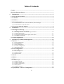
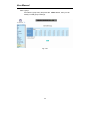
1-4-1. User Interfaces on the Front Panel (Button, LEDs and Plugs)
There are 44 TP Gigabit Ethernet ports and 4 SFP fiber ports for optional
removable modules on the front panel of the switch. LED display area, locating on
the left side of the panel, contains a Power LED, which indicates the power status
and 48 ports working status of the switch.
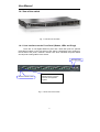
Fig. 1-1 Full View of the switch
Fig. 1-2 Front View of the switch
Power Indication LED
RESET B
utton
:
RESET button is used to
reset the management
system.
SFP Fiber Port

User Manual
7
• LED Indicators
LED Color
Function
System LED
POWER Green Lit when +5V DC power is on and good
CPU LED Green Blinks when CPU is activity
10/100/1000Ethernet TP Port 1 to 44 LED
LINK/ACT Green
Lit when connection with remote device is good
Blinks when any traffic is present
Off when cable connection is not good
10/100/1000Mbps
Green/
Amber
Lit green when 1000Mbps speed is active
Lit ember when 100Mbps speed is active
Off when 10Mbps speed is active
1000SX/LX Gigabit Fiber Port 45 to 48 LED
SFP(LINK/ACT) Green
Lit when connection with the remote device is good
Blinks when any traffic is present
Off when module connection is not good
Table1-1
T
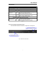
1-4-2. User Interfaces on the Rear Panel
One RS-232 DB-9 interface is offered for configuration or management.
Fig. 1-3 Rear View of the switch
RS
-
232 DB
-
9 Connector
AC Lin
e 100
-
240V 50/60 Hz

User Manual
8
1-5. View of the Optional Modules
In the switch, Port 45~48 include two types of media --- TP and SFP Fiber
(LC, BiDi LC...); they support 10/100/1000Mbps TP or 1000Mbps SFP Fiber with
auto-detected function. 1000Mbps SFP Fiber transceiver is used for high-speed
connection expansion; the following are optional SFP types provided for the switch:
1000Mbps LC, MM, SFP Fiber transceiver
T
(SFP.0LC.202)
T
1000Mbps LC, SM 10km, SFP Fiber transceiver
T
(SFP.0LC.212.10)
T
1000Mbps LC, SM 30km, SFP Fiber transceiver
T
(SFP.0LC.212.30)
T
1000Mbps LC, SM 50km, SFP Fiber transceiver
T
(SFP.0LC.212.50)
T
1000Mbps BiDi LC, type 1, SM 20km, SFP Fiber WDM transceiver
T
(SFP.0BL.621.201)
T
1000Mbps BiDi LC, type 2, SM 20km, SFP Fiber WDM transceiver
T
(SFP.0BL.621.202)
T
1000Mbps LC, SM 10km, SFP Fiber transceiver
T
with DDM
(SFP.DLC.212.10)
T
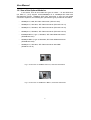
Fig. 1-4 Front View of 1000Base-SX/LX LC, SFP Fiber Transceiver
Fig. 1-5 Front View of
T
1000Base-LX BiDi LC, SFP Fiber Transceiver
T

User Manual
9
2. Installation
2-1. Starting the switch Up
This section will give users a quick start for:
-
Hardware and Cable Installation
- Management Station Installation
- Software booting and configuration
2-1-1. Hardware and Cable Installation
At the beginning, please do first:
⇒ Wear a grounding device to avoid the damage from electrostatic discharge
⇒ Be sure that power switch is OFF before you insert the power cord to power
source
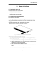
• To install Optional
T
SFP
T
Fiber Transceivers to the switch
T
Note: If you have no modules, please skip this section.
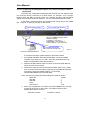
• Connecting the SFP Module to the Chassis:
The optional SFP modules are hot swappable, so you can plug or unplug it
before or after powering on.
1. Verify that the SFP module is the right model and conforms to the chassis
2. Slide the module along the slot. Also be sure that the module is properly
seated against the slot socket/connector
3. Install the media cable for network connection
4. Repeat the above steps, as needed, for each module to be installed into
slot(s)
5. Have the power ON after the above procedures are done
Fig. 2
-
1
Installation of
O
ptional
SFP
Fiber
T
ransceiver

User Manual
10
•
T
TP Port and Cable Installation
T
⇒ In the switch, TP port supports MDI/MDI-X auto-crossover, so both types of
cable, straight-through (Cable pin-outs for RJ-45 jack 1, 2, 3, 6 to 1, 2, 3, 6 in
10/100M TP; 1, 2, 3, 4, 5, 6, 7, 8 to 1, 2, 3, 4, 5, 6, 7, 8 in Gigabit TP) and
crossed-over (Cable pin-outs for RJ-45 jack 1, 2, 3, 6 to 3, 6, 1, 2) can be used.
It means you do not have to tell from them, just plug it.
⇒ Use Cat. 5 grade RJ-45 TP cable to connect to a TP port of the switch and the
other end is connected to a network-aware device such as a workstation or a
server.
⇒ Repeat the above steps, as needed, for each RJ-45 port to be connected to a
Gigabit 10/100/1000 TP device.
Now, you can start having the switch in operation.
•
T
Power On
T
The switch supports 100-240 VAC, 50-60 Hz power supply. The power
supply will automatically convert the local AC power source to DC power. It does not
matter whether any connection plugged into the switch or not when power on, even
modules as well. After the power is on, all LED indicators will light up immediately
and then all off except the power LED still keeps on. This represents a reset of the
system.
• Firm
T
ware Loading
T
After resetting, the bootloader will load the firmware into the memory. It will
take about 30 seconds, after that, the switch will flash all the LED once and
automatically performs self-test and is in ready state.

User Manual
11
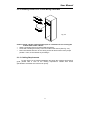
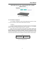
2-1-2. Installing Chassis to a 19-Inch Wiring Closet Rail
Caution: Allow a proper spacing and proper air ventilation for the cooling fan
at both sides of the chassis.
⇒
Wear a grounding device for electrostatic discharge.
⇒
Screw the mounting accessory to the front side of the switch (See Fig. 2-2).
⇒
Place the Chassis into the 19-inch wiring closet rail and locate it at the proper
position. Then, fix the Chassis by screwing it.
2-1-3. Cabling Requirements
To help ensure a successful installation and keep the network performance
good, please take a care on the cabling requirement. Cables with worse
specification will render the LAN to work poorly.
Fig. 2-2

User Manual
12
2-1-3-1. Cabling Requirements for TP Ports
⇒ For Fast Ethernet TP network connection
The grade of the cable must be Cat. 5 or Cat. 5e with a maximum length of
100 meters.
⇒ Gigabit Ethernet TP network connection
The grade of the cable must be Cat. 5 or Cat. 5e with a maximum length of
100 meters. Cat. 5e is recommended.
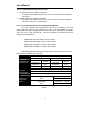
2-1-3-2. Cabling Requirements for 1000SX/LX SFP Module
It is more complex and comprehensive contrast to TP cabling in the fiber
media. Basically, there are two categories of fiber, multi mode (MM) and single
mode (SM). The later is categorized into several classes by the distance it supports.
They are SX, LX, LHX, XD, and ZX. From the viewpoint of connector type, there
mainly are LC and BIDI LC.
Gigabit Fiber with multi-mode LC SFP module
Gigabit Fiber with single-mode LC SFP module
Gigabit Fiber with BiDi LC 1310nm SFP module
Gigabit Fiber with BiDi LC 1550nm SFP module
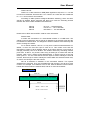
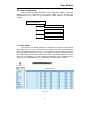
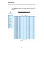
The following table lists the types of fiber that we support and those else not
listed here are available upon request.
Multi-mode Fiber Cable and Modal Bandwidth
Multi-mode 62.5/125µm Multi-mode 50/125µm
Modal
Bandwidth
Distance
Modal
Bandwidth
Distance
160MHz-Km 220m 400MHz-Km 500m
IEEE 802.3z
Gigabit Ethernet
1000SX 850nm
200MHz-Km 275m 500MHz-Km 550m
Single-mode Fiber 9/125µm
Single-mode transceiver 1310nm 10Km
1000Base-
LX/LHX/XD/ZX
Single-mode transceiver 1550nm 30, 50Km
TX(Transmit) 1310nm
Single-Mode
*20Km
RX(Receive) 1550nm
TX(Transmit) 1550nm
1000Base-LX
Single Fiber
(BIDI LC)
Single-Mode
*20Km
RX(Receive) 1310nm
Table2-1

User Manual
13
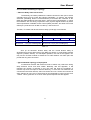
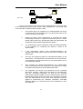
2-1-3-3. Switch Cascading in Topology
• Takes the Delay Time into Account
Theoretically, the switch partitions the collision domain for each port in switch
cascading that you may up-link the switches unlimitedly. In practice, the network
extension (cascading levels & overall diameter) must follow the constraint of the
IEEE 802.3/802.3u/802.3z and other 802.1 series protocol specifications, in which
the limitations are the timing requirement from physical signals defined by 802.3
series specification of Media Access Control (MAC) and PHY, and timer from some
OSI layer 2 protocols such as 802.1d, 802.1q, LACP and so on.
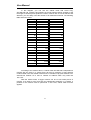
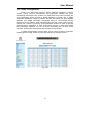
The fiber, TP cables and devices’ bit-time delay (round trip) are as follows:
1000Base-X TP, Fiber 100Base-TX TP 100Base-FX Fiber
Round trip Delay: 4096 Round trip Delay: 512
Cat. 5 TP Wire:
11.12/m Cat. 5 TP Wire:
1.12/m
Fiber Cable: 1.0/m
Fiber Cable : 10.10/m TP to fiber Converter: 56
Bit Time unit : 1ns (1sec./1000 Mega bit)
Bit Time unit: 0.01µs (1sec./100 Mega bit)
Table 2-2
Sum up all elements’ bit-time delay and the overall bit-time delay of
wires/devices must be within Round Trip Delay (bit times) in a half-duplex network
segment (collision domain). For full-duplex operation, this will not be applied. You
may use the TP-Fiber module to extend the TP node distance over fiber optic and
provide the long haul connection.
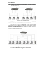
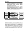
• Typical Network Topology in Deployment
A hierarchical network with minimum levels of switch may reduce the timing
delay between server and client station. Basically, with this approach, it will
minimize the number of switches in any one path; will lower the possibility of
network loop and will improve network efficiency. If more than two switches are
connected in the same network, select one switch as Level 1 switch and connect all
other switches to it at Level 2. Server/Host is recommended to connect to the Level
1 switch. This is general if no VLAN or other special requirements are applied.

User Manual
14
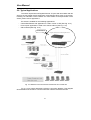
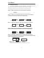
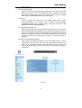
Case1: All switch ports are in the same local area network. Every port can access
each other (See Fig. 2-3).
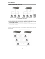
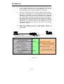
If VLAN is enabled and configured, each node in the network that can
communicate each other directly is bounded in the same VLAN area.
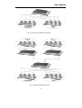
Here VLAN area is defined by what VLAN you are using. The switch
supports both port-based VLAN and tag-based VLAN. They are different in practical
deployment, especially in physical location. The following diagram shows how it
works and what the difference they are.
Case2a: Port-based VLAN (See Fig.2-4).
1. The same VLAN members could not be in different switches.
Fig. 2
-
3
No VLAN Configuration Diagram
Fig. 2-4 Port-based VLAN Diagram
Page is loading ...
Page is loading ...
Page is loading ...
Page is loading ...
Page is loading ...
Page is loading ...
Page is loading ...
Page is loading ...
Page is loading ...
Page is loading ...
Page is loading ...
Page is loading ...
Page is loading ...
Page is loading ...
Page is loading ...
Page is loading ...
Page is loading ...
Page is loading ...
Page is loading ...
Page is loading ...
Page is loading ...
Page is loading ...
Page is loading ...
Page is loading ...
Page is loading ...
Page is loading ...
Page is loading ...
Page is loading ...
Page is loading ...
Page is loading ...
Page is loading ...
Page is loading ...
Page is loading ...
Page is loading ...
Page is loading ...
Page is loading ...
Page is loading ...
Page is loading ...
Page is loading ...
Page is loading ...
Page is loading ...
Page is loading ...
Page is loading ...
Page is loading ...
Page is loading ...
Page is loading ...
Page is loading ...
Page is loading ...
Page is loading ...
Page is loading ...
Page is loading ...
Page is loading ...
Page is loading ...
Page is loading ...
Page is loading ...
Page is loading ...
Page is loading ...
Page is loading ...
Page is loading ...
Page is loading ...
Page is loading ...
Page is loading ...
Page is loading ...
Page is loading ...
Page is loading ...
Page is loading ...
Page is loading ...
Page is loading ...
Page is loading ...
Page is loading ...
Page is loading ...
Page is loading ...
Page is loading ...
Page is loading ...
Page is loading ...
Page is loading ...
Page is loading ...
Page is loading ...
Page is loading ...
Page is loading ...
Page is loading ...
Page is loading ...
Page is loading ...
Page is loading ...
Page is loading ...
Page is loading ...
Page is loading ...
Page is loading ...
Page is loading ...
Page is loading ...
Page is loading ...
Page is loading ...
Page is loading ...
Page is loading ...
Page is loading ...
Page is loading ...
Page is loading ...
Page is loading ...
Page is loading ...
Page is loading ...
Page is loading ...
Page is loading ...
Page is loading ...
Page is loading ...
Page is loading ...
Page is loading ...
Page is loading ...
Page is loading ...
Page is loading ...
Page is loading ...
Page is loading ...
Page is loading ...
Page is loading ...
Page is loading ...
Page is loading ...
Page is loading ...
Page is loading ...
Page is loading ...
Page is loading ...
Page is loading ...
Page is loading ...
Page is loading ...
Page is loading ...
Page is loading ...
Page is loading ...
Page is loading ...
Page is loading ...
Page is loading ...
Page is loading ...
Page is loading ...
Page is loading ...
Page is loading ...
Page is loading ...
Page is loading ...
Page is loading ...
Page is loading ...
Page is loading ...
Page is loading ...
Page is loading ...
Page is loading ...
Page is loading ...
Page is loading ...
Page is loading ...
Page is loading ...
Page is loading ...
Page is loading ...
Page is loading ...
Page is loading ...
Page is loading ...
Page is loading ...
Page is loading ...
Page is loading ...
Page is loading ...
Page is loading ...
Page is loading ...
Page is loading ...
Page is loading ...
Page is loading ...
Page is loading ...
Page is loading ...
Page is loading ...
Page is loading ...
Page is loading ...
Page is loading ...
Page is loading ...
Page is loading ...
Page is loading ...
Page is loading ...
Page is loading ...
Page is loading ...
Page is loading ...
Page is loading ...
Page is loading ...
Page is loading ...
Page is loading ...
Page is loading ...
Page is loading ...
Page is loading ...
Page is loading ...
Page is loading ...
Page is loading ...
Page is loading ...
Page is loading ...
Page is loading ...
Page is loading ...
Page is loading ...
Page is loading ...
Page is loading ...
Page is loading ...
Page is loading ...
Page is loading ...
Page is loading ...
Page is loading ...
Page is loading ...
Page is loading ...
Page is loading ...
Page is loading ...
Page is loading ...
Page is loading ...
Page is loading ...
Page is loading ...
Page is loading ...
Page is loading ...
Page is loading ...
Page is loading ...
Page is loading ...
Page is loading ...
Page is loading ...
Page is loading ...
Page is loading ...
Page is loading ...
Page is loading ...
Page is loading ...
Page is loading ...
Page is loading ...
Page is loading ...
Page is loading ...
Page is loading ...
Page is loading ...
Page is loading ...
Page is loading ...
Page is loading ...
Page is loading ...
Page is loading ...
Page is loading ...
Page is loading ...
Page is loading ...
Page is loading ...
Page is loading ...
Page is loading ...
Page is loading ...
Page is loading ...
Page is loading ...
Page is loading ...
Page is loading ...
Page is loading ...
Page is loading ...
Page is loading ...
Page is loading ...
Page is loading ...
Page is loading ...
Page is loading ...
Page is loading ...
Page is loading ...
Page is loading ...
Page is loading ...
Page is loading ...
Page is loading ...
Page is loading ...
Page is loading ...
Page is loading ...
Page is loading ...
Page is loading ...
Page is loading ...
Page is loading ...
Page is loading ...
Page is loading ...
Page is loading ...
Page is loading ...
Page is loading ...
Page is loading ...
Page is loading ...
Page is loading ...
Page is loading ...
Page is loading ...
Page is loading ...
Page is loading ...
-
 1
1
-
 2
2
-
 3
3
-
 4
4
-
 5
5
-
 6
6
-
 7
7
-
 8
8
-
 9
9
-
 10
10
-
 11
11
-
 12
12
-
 13
13
-
 14
14
-
 15
15
-
 16
16
-
 17
17
-
 18
18
-
 19
19
-
 20
20
-
 21
21
-
 22
22
-
 23
23
-
 24
24
-
 25
25
-
 26
26
-
 27
27
-
 28
28
-
 29
29
-
 30
30
-
 31
31
-
 32
32
-
 33
33
-
 34
34
-
 35
35
-
 36
36
-
 37
37
-
 38
38
-
 39
39
-
 40
40
-
 41
41
-
 42
42
-
 43
43
-
 44
44
-
 45
45
-
 46
46
-
 47
47
-
 48
48
-
 49
49
-
 50
50
-
 51
51
-
 52
52
-
 53
53
-
 54
54
-
 55
55
-
 56
56
-
 57
57
-
 58
58
-
 59
59
-
 60
60
-
 61
61
-
 62
62
-
 63
63
-
 64
64
-
 65
65
-
 66
66
-
 67
67
-
 68
68
-
 69
69
-
 70
70
-
 71
71
-
 72
72
-
 73
73
-
 74
74
-
 75
75
-
 76
76
-
 77
77
-
 78
78
-
 79
79
-
 80
80
-
 81
81
-
 82
82
-
 83
83
-
 84
84
-
 85
85
-
 86
86
-
 87
87
-
 88
88
-
 89
89
-
 90
90
-
 91
91
-
 92
92
-
 93
93
-
 94
94
-
 95
95
-
 96
96
-
 97
97
-
 98
98
-
 99
99
-
 100
100
-
 101
101
-
 102
102
-
 103
103
-
 104
104
-
 105
105
-
 106
106
-
 107
107
-
 108
108
-
 109
109
-
 110
110
-
 111
111
-
 112
112
-
 113
113
-
 114
114
-
 115
115
-
 116
116
-
 117
117
-
 118
118
-
 119
119
-
 120
120
-
 121
121
-
 122
122
-
 123
123
-
 124
124
-
 125
125
-
 126
126
-
 127
127
-
 128
128
-
 129
129
-
 130
130
-
 131
131
-
 132
132
-
 133
133
-
 134
134
-
 135
135
-
 136
136
-
 137
137
-
 138
138
-
 139
139
-
 140
140
-
 141
141
-
 142
142
-
 143
143
-
 144
144
-
 145
145
-
 146
146
-
 147
147
-
 148
148
-
 149
149
-
 150
150
-
 151
151
-
 152
152
-
 153
153
-
 154
154
-
 155
155
-
 156
156
-
 157
157
-
 158
158
-
 159
159
-
 160
160
-
 161
161
-
 162
162
-
 163
163
-
 164
164
-
 165
165
-
 166
166
-
 167
167
-
 168
168
-
 169
169
-
 170
170
-
 171
171
-
 172
172
-
 173
173
-
 174
174
-
 175
175
-
 176
176
-
 177
177
-
 178
178
-
 179
179
-
 180
180
-
 181
181
-
 182
182
-
 183
183
-
 184
184
-
 185
185
-
 186
186
-
 187
187
-
 188
188
-
 189
189
-
 190
190
-
 191
191
-
 192
192
-
 193
193
-
 194
194
-
 195
195
-
 196
196
-
 197
197
-
 198
198
-
 199
199
-
 200
200
-
 201
201
-
 202
202
-
 203
203
-
 204
204
-
 205
205
-
 206
206
-
 207
207
-
 208
208
-
 209
209
-
 210
210
-
 211
211
-
 212
212
-
 213
213
-
 214
214
-
 215
215
-
 216
216
-
 217
217
-
 218
218
-
 219
219
-
 220
220
-
 221
221
-
 222
222
-
 223
223
-
 224
224
-
 225
225
-
 226
226
-
 227
227
-
 228
228
-
 229
229
-
 230
230
-
 231
231
-
 232
232
-
 233
233
-
 234
234
-
 235
235
-
 236
236
-
 237
237
-
 238
238
-
 239
239
-
 240
240
-
 241
241
-
 242
242
-
 243
243
-
 244
244
-
 245
245
-
 246
246
-
 247
247
-
 248
248
-
 249
249
-
 250
250
-
 251
251
-
 252
252
-
 253
253
-
 254
254
-
 255
255
-
 256
256
-
 257
257
-
 258
258
-
 259
259
-
 260
260
-
 261
261
-
 262
262
-
 263
263
-
 264
264
-
 265
265
-
 266
266
-
 267
267
-
 268
268
-
 269
269
-
 270
270
-
 271
271
-
 272
272
-
 273
273
-
 274
274
-
 275
275
-
 276
276
-
 277
277
-
 278
278
-
 279
279
-
 280
280
-
 281
281
-
 282
282
-
 283
283
-
 284
284
-
 285
285
-
 286
286
-
 287
287


LevelOne ProCon GSW-4896 User manual
- Category
- Network switches
- Type
- User manual
Ask a question and I''ll find the answer in the document
Finding information in a document is now easier with AI
Related papers
-
LevelOne GEP-2450 User manual
-
LevelOne GSW-2494 User manual
-
-
-
-
LevelOne ProCon GSW-2693 User manual
-
-
-
-
Other documents
-
MicroNet SP6524PWS User manual
-
Ruby Tech FGS-2824 User manual
-
-
-
Draytek VigorSwitch P2260 User manual
-
Edimax Technology ES-5224RM+ Gigabit Ethernet Switch User manual
-
-
-
Repotec RP-PG081W Owner's manual
-
KTI Networks KGS-2420 User manual