Drawer Slides
©2005 LHMC
Ball-Bearing Side-Mount
Drawer Slides
Before You Begin
• Read the Do-It-Yourself Installation Instructions completely
before starting.
• Make sure all parts are included.
Parts List
• 2 Side-Mount Drawer Slides
• 12 #6 x 7/16 pan head wood screws
Recommended Tools
• Screwdriver
• Pencil or Scribe
• Ruler
• Level
Data
• 100 lb. Capacity per pair
• Length of 14”, 16”, 18”, 20”, 22”, 24”
Specifications
Drawer or Pull-Out-Shelf (For TV, VCR and Stereo Equipment)
• Drawer pull-out shelf must be 1/2” narrower than cabinet opening on
each side.
• Top and bottom of drawer or pull-out-shelf bottom should have 1/8”
minimum clearance from the cabinet opening.
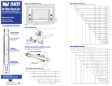
1. Installing Cabinet Members to Cabinet
Press release lever to disconnect drawer members. Using a level place
and align cabinet member into position and place side flush with the
cabinet edge. Fasten each slide with three #6 pan head wood screws.
You will need to move the slide member back and forth to access the
screw holes. For supporting heavy objects use five #8-32 machine screws
and inserts to avoid tear out of slide.
2. Installing Drawer Members to Drawer or Pull-Out-Shelf
On drawer place and align drawer member into position. Place drawer
member end flush with the drawer overlay. Fasten each drawer member
with three #6 pan head wood screws.
3. Inserting Drawer
Insert drawer into cabinet and close. The drawer slide release lever will
lock as drawer is closed. Make sure drawer aligns properly and rides
smoothly on the side mount drawer slides.
1
2
Cabinet
Drawer or pull-out shelf
Side mount drawer slide
Slide member
Cabinet member
Release lever
Drawer member
Cabinet member
Slide member
Align to edge
Align to edge
Drawer
D806
Series
SPECIFICATIONS

Drawer Slides
©2005 LHMC
Face Frame Drawer Socket / Bracket
For D806 Series Full-Extension
Ball-Bearing Drawer Slides
(Available in 14”-24” lengths, sold separately)
Slide /Socket Parameters
• Proper installation of sockets will assure equally spaced and level drawer
slides. This is essential for optimum slide performance.
1. Measurement
The left and right drawer slides must have the same height. This
measurement is taken from the bottom of the cabinet (see step 1, ill. A, right).
Record this measurement for the installation process. The front of the drawer
slides must be level with the rear of the drawer slides (see step 1, ill. B, right).
Position the drawer slides, as they will be mounted in cabinet. Measure the
distance between the front side rails of the drawer slides. This measurement
is the width of the drawer slides. Use this measurement to calculate the
correct distance between the rear sockets. Record all measurements for
installation process (see step 1, ill. C, right).
2. Installation
Socket/Slide Bracket to Drawer Slide
Slip socket onto the rear of each drawer slide. Make sure that the drawer
slide is fully seated (bottoms out) in the sockets. Position front drawer slide
mounting bracket flush to the front of the side rail and fully extend drawer
slide (see step 2, ill. A, below). Align holes in drawer slide with front mounting
bracket and fasten bracket to the side rail using (2) #6 x 5/8 pan head screws
(provided).
Drawer Slide to Cabinet
Position front drawer slide mounting bracket against the inside of the
cabinet face using the height measurements recorded in step 1. Make sure
that the corner of front bracket is flush with the inside corner of the cabinet
face by pushing front bracket forward to seat it with the inside corner of
cabinet face (see step 2, ill. B, below). Hold front mounting bracket in place
and fasten mounting bracket to inside of cabinet face using (2) ea. #6 x K”
pan head screws (provided). Do not staple. Push sockets against the rear of
the cabinet. Using the measurements recorded in step 1, align the left and
right rear drawer slide with left and right front drawer slide (see step 1, ill. C,
right). Make sure that left and right drawer slides are parallel to each other.
Fasten socket to the rear of the cabinet using vertical holes and (1) ea.
#6 x 5/8” pan head screws (provided). Do not tighten completely, snug will do.
3. Adjustment
Adjust Socket
With the drawer closed, check the alignment of drawer relative to the case.
If necessary, adjust the socket position vertically to correct for gaps. Install
additional #6 x 5/8” pan head screws into remaining holes of sockets to
secure the sockets in the desired position. The drawer front should fit flush
with the cabinet face.
2
1
A
C
B
Rear Socket
A
B
Cabinet Face
Front
Bracket
D806 Series
Continued
Face Frame
(Front of Cabinet)
FRONT VIEW
TOP VIEW
SIDE VIEW
Face Frame
(Front of Cabinet)
Slide Height Needs To Be
The Same At Front And Back
4mm
1/2” MAX
(12.7mm)
Face Frame
Side Panel
Back Panel
Distance
Between
Channels
Distance
Between
Channels
Minus 3-1/4”
Front Bracket
Slide Height Needs
To Be The Same
Side To Side
-
 1
1
-
 2
2
Liberty D80614C-W Installation guide
- Type
- Installation guide
- This manual is also suitable for
Ask a question and I''ll find the answer in the document
Finding information in a document is now easier with AI
Related papers
Other documents
-
Husky TB-303B Operating instructions
-
 Knape & Vogt 8405 Installation guide
-
 ClosetMaid MasterSuite Installer's Assembly, Installation & Reference Manual
-
 KraftMaid VC4821L6S7.RBE.7118PN Installation guide
-
Craftsman 113198410 Owner's manual
-
Everbilt 4510S-14 Operating instructions
-
Knape & Vogt 8417P 16 Installation guide
-
Everbilt D94224E-ZP-W Installation guide
-
Knape & Vogt 8450FMP 20 Installation guide
-
Midmark Artizan® Expressions Operatory Cabinetry - Modular Cabinetry Installation guide


