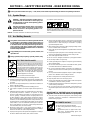
Miller MD272649D Owner's manual
- Category
- Welding System
- Type
- Owner's manual
This manual is also suitable for

Processes
Description
MIG (GMAW) Welding
Flux Cored (FCAW) Welding
Wire Feeder
OM-216 655N 2013−07
ST 44 Series Wire Feeder
CE
www.MillerWelds.com
OWNER’S MANUAL

Thank you and congratulations on choosing Miller. Now you can get the
job done and get it done right. We know you don’t have time to do it any
other way.
That’s why when Niels Miller first started building arc welders in 1929,
he made sure his products offered long-lasting value and superior quality.
Like you, his customers couldn’t afford anything less. Miller products had
to be more than the best they could be. They had to be the best you could
buy.
Today, the people that build and sell Miller products continue the
tradition. They’re just as committed to providing equipment and service
that meets the high standards of quality and value established in 1929.
This Owner’s Manual is designed to help you get the most out of your
Miller products. Please take time to read the Safety precautions. They will
help you protect yourself against potential hazards on the worksite. We’ve
made installation and operation quick and easy. With Miller you can
count on years of reliable service with proper maintenance. And if for
some reason the unit needs repair, there’s a Troubleshooting section that
will help you figure out what the problem is. The parts list will then help
you to decide which exact part you may need to fix the problem.
Warranty and service information for your particular model are also
provided.
Miller Electric manufactures a full line of
welders and welding related equipment. For
information on other quality Miller products, contact your local Miller
distributor to receive the latest full line catalog or individual catalog sheets.
Working as hard as you do
− every power source from
Miller is backed by the most
hassle-free warranty in the
business.
From Miller to You

TABLE OF CONTENTS
SECTION 1 − SAFETY PRECAUTIONS - READ BEFORE USING 1.................................
1-1. Symbol Usage 1.......................................................................
1-2. Arc Welding Hazards 1.................................................................
1-3. Additional Symbols For Installation, Operation, And Maintenance 3.............................
1-4. California Proposition 65 Warnings 4......................................................
1-5. Principal Safety Standards 4.............................................................
1-6. EMF Information 4.....................................................................
SECTION 2 − DEFINITIONS 5..................................................................
2-1. Additional Safety Symbols And Definitions 5................................................
2-2. Miscellaneous Symbols and Definitions 6..................................................
SECTION 3 − SPECIFICATIONS 7..............................................................
3-1. Serial Number And Rating Label Location 7................................................
3-2. Unit Specifications 7....................................................................
3-3. Environmental Specifications 7...........................................................
3-4. Gun Recommendation Table 7...........................................................
SECTION 4 − INSTALLATION 8................................................................
4-1. Equipment Connection Diagrams 8.......................................................
4-2. 14-Pin Plug Information 8................................................................
4-3. Connecting Welding Gun And Weld Cable 8................................................
4-4. Installing Wire Guide And Drive Roll 9.....................................................
SECTION 5 − OPERATION 10...................................................................
5-1. ST 44 Series Panel Controls 10...........................................................
5-2. Run-In Control and Burnback Control 10....................................................
SECTION 6 − MAINTENANCE & TROUBLESHOOTING 11.........................................
6-1. Routine Maintenance 11.................................................................
6-2. Troubleshooting 12......................................................................
SECTION 6 − ELECTRICAL DIAGRAM 13........................................................
SECTION 7 − PARTS LIST 14...................................................................
WARRANTY

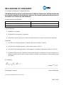
DECLARATION OF CONFORMITY
for European Community (CE marked) products.
ITW Welding Products Italy S.r.l Via Privata Iseo 6/E, 20098 San Giuliano M.se, (MI) Italy declares that
the product(s) identified in this declaration conform to the essential requirements and provisions of
the stated Council Directive(s) and Standard(s).
Product/Apparatus Identification:
Product Stock Number
ST 44 029007406
ST 44 c/w Digital A/V/WFS, Water Kit 029007404
Council Directives:
S 2006/95/EC Low Voltage
S 2004/108/EC Electromagnetic Compatibility
S 2011/65/EU Restriction of the use of certain hazardous substances in electrical and electronic equipment
Standards:
S IEC 60974-1 Arc Welding Equipment - Welding Power Sources: edition 3, 2005-07.
S IEC 60974-5 Arc Welding Equipment – Wire Feeders: edition 2, 2007-11.
S IEC 60974-10 Arc Welding Equipment - Electromagnetic Compatibility Requirements: edition 2.0, 2007-08.
S EN 50445:2008 Product family standard to demonstrate compliance of equipment for resistance welding, arc
welding and allied processes with the basic restrictions related to human exposure to electromagnetic fields
(0Hz-300Hz)
EU Signatory:
January 2
nd
, 2013
___________________________________________________________________________________
Massimigliano Lavarini Date of Declaration
ELECTRONIC ENGINEER R&D TECH. SUPPORT
956 172 037

OM-216 655 Page 1
SECTION 1 − SAFETY PRECAUTIONS - READ BEFORE USING
som 2011−10
7
Protect yourself and others from injury — read, follow, and save these important safety precautions and operating instructions.
1-1. Symbol Usage
DANGER! − Indicates a hazardous situation which, if
not avoided, will result in death or serious injury. The
possible hazards are shown in the adjoining symbols
or explained in the text.
Indicates a hazardous situation which, if not avoided,
could result in death or serious injury. The possible
hazards are shown in the adjoining symbols or ex-
plained in the text.
NOTICE − Indicates statements not related to personal injury.
. Indicates special instructions.
This group of symbols means Warning! Watch Out! ELECTRIC
SHOCK, MOVING PARTS, and HOT PARTS hazards. Consult sym-
bols and related instructions below for necessary actions to avoid the
hazards.
1-2. Arc Welding Hazards
The symbols shown below are used throughout this manual
to call attention to and identify possible hazards. When you
see the symbol, watch out, and follow the related instructions
to avoid the hazard. The safety information given below is
only a summary of the more complete safety information
found in the Safety Standards listed in Section 1-5. Read and
follow all Safety Standards.
Only qualified persons should install, operate, maintain, and
repair this unit.
During operation, keep everybody, especially children, away.
ELECTRIC SHOCK can kill.
Touching live electrical parts can cause fatal shock
s
or severe burns. The electrode and work circuit i
s
electrically live whenever the output is on. The inpu
t
power circuit and machine internal circuits are also
live when power is on. In semiautomatic or automati
c
wire welding, the wire, wire reel, drive roll housing
,
and all metal parts touching the welding wire are
electrically live. Incorrectly installed or improperl
y
grounded equipment is a hazard.
D Do not touch live electrical parts.
D Wear dry, hole-free insulating gloves and body protection.
D Insulate yourself from work and ground using dry insulating mats
or covers big enough to prevent any physical contact with the work
or ground.
D Do not use AC output in damp areas, if movement is confined, or if
there is a danger of falling.
D Use AC output ONLY if required for the welding process.
D If AC output is required, use remote output control if present on
unit.
D Additional safety precautions are required when any of the follow-
ing electrically hazardous conditions are present: in damp
locations or while wearing wet clothing; on metal structures such
as floors, gratings, or scaffolds; when in cramped positions such
as sitting, kneeling, or lying; or when there is a high risk of unavoid-
able or accidental contact with the workpiece or ground. For these
conditions, use the following equipment in order presented: 1) a
semiautomatic DC constant voltage (wire) welder, 2) a DC manual
(stick) welder, or 3) an AC welder with reduced open-circuit volt-
age. In most situations, use of a DC, constant voltage wire welder
is recommended. And, do not work alone!
D Disconnect input power or stop engine before installing or
servicing this equipment. Lockout/tagout input power according to
OSHA 29 CFR 1910.147 (see Safety Standards).
D Properly install, ground, and operate this equipment according to
its Owner’s Manual and national, state, and local codes.
D Always verify the supply ground − check and be sure that input
power cord ground wire is properly connected to ground terminal in
disconnect box or that cord plug is connected to a properly
grounded receptacle outlet.
D When making input connections, attach proper grounding conduc-
tor first − double-check connections.
D Keep cords dry, free of oil and grease, and protected from hot metal
and sparks.
D Frequently inspect input power cord for damage or bare wiring −
replace cord immediately if damaged − bare wiring can kill.
D Turn off all equipment when not in use.
D Do not use worn, damaged, undersized, or poorly spliced cables.
D Do not drape cables over your body.
D If earth grounding of the workpiece is required, ground it directly
with a separate cable.
D Do not touch electrode if you are in contact with the work, ground,
or another electrode from a different machine.
D Do not touch electrode holders connected to two welding ma-
chines at the same time since double open-circuit voltage will be
present.
D Use only well-maintained equipment. Repair or replace damaged
parts at once. Maintain unit according to manual.
D Wear a safety harness if working above floor level.
D Keep all panels and covers securely in place.
D Clamp work cable with good metal-to-metal contact to workpiece
or worktable as near the weld as practical.
D Insulate work clamp when not connected to workpiece to prevent
contact with any metal object.
D Do not connect more than one electrode or work cable to any
single weld output terminal. Disconnect cable for process not in
use.
SIGNIFICANT DC VOLTAGE exists in inverter weld-
ing power sources AFTER removal of input power.
D Turn Off inverter, disconnect input power, and discharge input
capacitors according to instructions in Maintenance Section
before touching any parts.
HOT PARTS can burn.
D Do not touch hot parts bare handed.
D Allow cooling period before working on equip-
ment.
D To handle hot parts, use proper tools and/or
wear heavy, insulated welding gloves and
clothing to prevent burns.

OM-216 665 Page 2
Welding produces fumes and gases. Breathing
these fumes and gases can be hazardous to your
health.
FUMES AND GASES can be hazardous.
D Keep your head out of the fumes. Do not breathe the fumes.
D If inside, ventilate the area and/or use local forced ventilation at the
arc to remove welding fumes and gases.
D If ventilation is poor, wear an approved air-supplied respirator.
D Read and understand the Material Safety Data Sheets (MSDSs)
and the manufacturer’s instructions for metals, consumables,
coatings, cleaners, and degreasers.
D Work in a confined space only if it is well ventilated, or while
wearing an air-supplied respirator. Always have a trained watch-
person nearby. Welding fumes and gases can displace air and
lower the oxygen level causing injury or death. Be sure the breath-
ing air is safe.
D Do not weld in locations near degreasing, cleaning, or spraying op-
erations. The heat and rays of the arc can react with vapors to form
highly toxic and irritating gases.
D Do not weld on coated metals, such as galvanized, lead, or
cadmium plated steel, unless the coating is removed from the weld
area, the area is well ventilated, and while wearing an air-supplied
respirator. The coatings and any metals containing these elements
can give off toxic fumes if welded.
Arc rays from the welding process produce intense
visible and invisible (ultraviolet and infrared) rays
that can burn eyes and skin. Sparks fly off from the
weld.
D Wear an approved welding helmet fitted with a proper shade of
filter lenses to protect your face and eyes from arc rays and
sparks when welding or watching (see ANSI Z49.1 and Z87.1
listed in Safety Standards).
D Wear approved safety glasses with side shields under your
helmet.
D Use protective screens or barriers to protect others from flash,
glare and sparks; warn others not to watch the arc.
D Wear protective clothing made from durable, flame-resistant
material (leather, heavy cotton, or wool) and foot protection.
ARC RAYS can burn eyes and skin.
Welding on closed containers, such as tanks,
drums, or pipes, can cause them to blow up. Sparks
can fly off from the welding arc. The flying sparks, hot
workpiece, and hot equipment can cause fires and
burns. Accidental contact of electrode to metal objects can cause
sparks, explosion, overheating, or fire. Check and be sure the area is
safe before doing any welding.
WELDING can cause fire or explosion.
D Remove all flammables within 35 ft (10.7 m) of the welding arc. If
this is not possible, tightly cover them with approved covers.
D Do not weld where flying sparks can strike flammable material.
D Protect yourself and others from flying sparks and hot metal.
D Be alert that welding sparks and hot materials from welding can
easily go through small cracks and openings to adjacent areas.
D Watch for fire, and keep a fire extinguisher nearby.
D Be aware that welding on a ceiling, floor, bulkhead, or partition can
cause fire on the hidden side.
D Do not weld on containers that have held combustibles, or on
closed containers such as tanks, drums, or pipes unless they are
properly prepared according to AWS F4.1 and AWS A6.0 (see
Safety Standards).
D Do not weld where the atmosphere may contain flammable dust,
gas, or liquid vapors (such as gasoline).
D Connect work cable to the work as close to the welding area as
practical to prevent welding current from traveling long, possibly
unknown paths and causing electric shock, sparks, and fire
hazards.
D Do not use welder to thaw frozen pipes.
D Remove stick electrode from holder or cut off welding wire at
contact tip when not in use.
D Wear oil-free protective garments such as leather gloves, heavy
shirt, cuffless trousers, high shoes, and a cap.
D Remove any combustibles, such as a butane lighter or matches,
from your person before doing any welding.
D After completion of work, inspect area to ensure it is free of sparks,
glowing embers, and flames.
D Use only correct fuses or circuit breakers. Do not oversize or by-
pass them.
D Follow requirements in OSHA 1910.252 (a) (2) (iv) and NFPA 51B
for hot work and have a fire watcher and extinguisher nearby.
FLYING METAL or DIRT can injure eyes.
D Welding, chipping, wire brushing, and grinding
cause sparks and flying metal. As welds cool,
they can throw off slag.
D Wear approved safety glasses with side
shields even under your welding helmet.
BUILDUP OF GAS can injure or kill.
D Shut off compressed gas supply when not in use.
D Always ventilate confined spaces or use
approved air-supplied respirator.
ELECTRIC AND MAGNETIC FIELDS (EM
F)
can affect Implanted Medical Devices.
D Wearers of Pacemakers and other Implante
d
Medical Devices should keep away.
D Implanted Medical Device wearers should consult their docto
r
and the device manufacturer before going near arc welding, spo
t
welding, gouging, plasma arc cutting, or induction heating
operations.
NOISE can damage hearing.
Noise from some processes or equipment can
damage hearing.
D Wear approved ear protection if noise level is
high.
Compressed gas cylinders contain gas under high
pressure. If damaged, a cylinder can explode. Since
gas cylinders are normally part of the welding
process, be sure to treat them carefully.
CYLINDERS can explode if damaged.
D Protect compressed gas cylinders from excessive heat, mechani-
cal shocks, physical damage, slag, open flames, sparks, and arcs.
D Install cylinders in an upright position by securing to a stationary
support or cylinder rack to prevent falling or tipping.
D Keep cylinders away from any welding or other electrical circuits.
D Never drape a welding torch over a gas cylinder.
D Never allow a welding electrode to touch any cylinder.
D Never weld on a pressurized cylinder − explosion will result.
D Use only correct compressed gas cylinders, regulators, hoses,
and fittings designed for the specific application; maintain them
and associated parts in good condition.
D Turn face away from valve outlet when opening cylinder valve.
D Keep protective cap in place over valve except when cylinder is in
use or connected for use.
D Use the right equipment, correct procedures, and sufficient num-
ber of persons to lift and move cylinders.
D Read and follow instructions on compressed gas cylinders,
associated equipment, and Compressed Gas Association (CGA)
publication P-1 listed in Safety Standards.

OM-216 655 Page 3
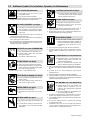
1-3. Additional Symbols For Installation, Operation, And Maintenance
FIRE OR EXPLOSION hazard.
D Do not install or place unit on, over, or near
combustible surfaces.
D Do not install unit near flammables.
D Do not overload building wiring − be sure power supply system is
properly sized, rated, and protected to handle this unit.
FALLING EQUIPMENT can injure.
D Use lifting eye to lift unit only, NOT running
gear, gas cylinders, or any other accessories.
D Use equipment of adequate capacity to lift and
support unit.
D If using lift forks to move unit, be sure forks are long enough to
extend beyond opposite side of unit.
D Keep equipment (cables and cords) away from moving vehicles
when working from an aerial location.
D Follow the guidelines in the Applications Manual for the Revised
NIOSH Lifting Equation (Publication No. 94−110) when manu-
ally lifting heavy parts or equipment.
OVERUSE can cause OVERHEATING
D Allow cooling period; follow rated duty cycle.
D Reduce current or reduce duty cycle before
starting to weld again.
D Do not block or filter airflow to unit.
FLYING SPARKS can injure.
D Wear a face shield to protect eyes and face.
D Shape tungsten electrode only on grinder with
proper guards in a safe location wearing proper
face, hand, and body protection.
D Sparks can cause fires — keep flammables away.
STATIC (ESD) can damage PC boards.
D Put on grounded wrist strap BEFORE handling
boards or parts.
D Use proper static-proof bags and boxes to
store, move, or ship PC boards.
MOVING PARTS can injure.
D Keep away from moving parts.
D Keep away from pinch points such as drive
rolls.
WELDING WIRE can injure.
D Do not press gun trigger until instructed to do
so.
D Do not point gun toward any part of the body,
other people, or any metal when threading
welding wire.
BATTERY EXPLOSION can injure.
D Do not use welder to charge batteries or jum
p
start vehicles unless it has a battery chargin
g
feature designed for this purpose.
MOVING PARTS can injure.
D Keep away from moving parts such as fans.
D Keep all doors, panels, covers, and guards
closed and securely in place.
D Have only qualified persons remove doors, panels, covers, or
guards for maintenance and troubleshooting as necessary.
D Reinstall doors, panels, covers, or guards when maintenance is
finished and before reconnecting input power.
READ INSTRUCTIONS.
D Read and follow all labels and the Owner’s
Manual carefully before installing, operating, or
servicing unit. Read the safety information at
the beginning of the manual and in each
section.
D Use only genuine replacement parts from the manufacturer.
D Perform maintenance and service according to the Owner’s
Manuals, industry standards, and national, state, and local
codes.
H.F. RADIATION can cause interference.
D High-frequency (H.F.) can interfere with radio
navigation, safety services, computers, and
communications equipment.
D Have only qualified persons familiar with
electronic equipment perform this installation.
D The user is responsible for having a qualified electrician prompt-
ly correct any interference problem resulting from the installa-
tion.
D If notified by the FCC about interference, stop using the
equipment at once.
D Have the installation regularly checked and maintained.
D Keep high-frequency source doors and panels tightly shut, keep
spark gaps at correct setting, and use grounding and shielding to
minimize the possibility of interference.
ARC WELDING can cause interference.
D Electromagnetic energy can interfere with
sensitive electronic equipment such as
computers and computer-driven equipment
such as robots.
D Be sure all equipment in the welding area is
electromagnetically compatible.
D To reduce possible interference, keep weld cables as short as
possible, close together, and down low, such as on the floor.
D Locate welding operation 100 meters from any sensitive elec-
tronic equipment.
D Be sure this welding machine is installed and grounded
according to this manual.
D If interference still occurs, the user must take extra measures
such as moving the welding machine, using shielded cables,
using line filters, or shielding the work area.

OM-216 665 Page 4
1-4. California Proposition 65 Warnings
Welding or cutting equipment produces fumes or gases
which contain chemicals known to the State of California to
cause birth defects and, in some cases, cancer. (California
Health & Safety Code Section 25249.5 et seq.)
This product contains chemicals, including lead, known to
the state of California to cause cancer, birth defects, or other
reproductive harm. Wash hands after use.
1-5. Principal Safety Standards
Safety in Welding, Cutting, and Allied Processes, ANSI Standard Z49.1,
is available as a free download from the American Welding Society at
http://www.aws.org or purchased from Global Engineering Documents
(phone: 1-877-413-5184, website: www.global.ihs.com).
Safe Practices for the Preparation of Containers and Piping for Welding
and Cutting, American Welding Society Standard AWS F4.1, from Glob-
al Engineering Documents (phone: 1-877-413-5184, website:
www.global.ihs.com).
Safe Practices for Welding and Cutting Containers that have Held Com-
bustibles, American Welding Society Standard AWS A6.0, from Global
Engineering Documents (phone: 1-877-413-5184,
website: www.global.ihs.com).
National Electrical Code, NFPA Standard 70, from National Fire Protec-
tion Association, Quincy, MA 02269 (phone: 1-800-344-3555, website:
www.nfpa.org and www. sparky.org).
Safe Handling of Compressed Gases in Cylinders, CGA Pamphlet P-1,
from Compressed Gas Association, 14501 George Carter Way, Suite
103, Chantilly, VA 20151 (phone: 703-788-2700, website:www.cga-
net.com).
Safety in Welding, Cutting, and Allied Processes, CSA Standard
W117.2, from Canadian Standards Association, Standards Sales, 5060
Spectrum Way, Suite 100, Ontario, Canada L4W 5NS (phone:
800-463-6727, website: www.csa-international.org).
Safe Practice For Occupational And Educational Eye And Face Protec-
tion, ANSI Standard Z87.1, from American National Standards Institute,
25 West 43rd Street, New York, NY 10036 (phone: 212-642-4900, web-
site: www.ansi.org).
Standard for Fire Prevention During Welding, Cutting, and Other Hot
Work, NFPA Standard 51B, from National Fire Protection Association,
Quincy, MA 02269 (phone: 1-800-344-3555, website: www.nfpa.org.
OSHA, Occupational Safety and Health Standards for General Indus-
try, Title 29, Code of Federal Regulations (CFR), Part 1910, Subpart Q,
and Part 1926, Subpart J, from U.S. Government Printing Office, Super-
intendent of Documents, P.O. Box 371954, Pittsburgh, PA 15250-7954
(phone: 1-866-512-1800) (there are 10 OSHA Regional Offices—
phone for Region 5, Chicago, is 312-353-2220, website:
www.osha.gov).
Applications Manual for the Revised NIOSH Lifting Equation, The Na-
tional Institute for Occupational Safety and Health (NIOSH), 1600
Clifton Rd, Atlanta, GA 30333 (phone: 1-800-232-4636, website:
www.cdc.gov/NIOSH).
1-6. EMF Information
Electric current flowing through any conductor causes localized electric
and magnetic fields (EMF). Welding current creates an EMF field
around the welding circuit and welding equipment. EMF fields may inter-
fere with some medical implants, e.g. pacemakers. Protective
measures for persons wearing medical implants have to be taken. For
example, restrict access for passers−by or conduct individual risk as-
sessment for welders. All welders should use the following procedures
in order to minimize exposure to EMF fields from the welding circuit:
1. Keep cables close together by twisting or taping them, or using a
cable cover.
2. Do not place your body between welding cables. Arrange cables
to one side and away from the operator.
3. Do not coil or drape cables around your body.
4. Keep head and trunk as far away from the equipment in the
welding circuit as possible.
5. Connect work clamp to workpiece as close to the weld as
possible.
6. Do not work next to, sit or lean on the welding power source.
7. Do not weld whilst carrying the welding power source or wire
feeder.
About Implanted Medical Devices:
Implanted Medical Device wearers should consult their doctor and the
device manufacturer before performing or going near arc welding, spot
welding, gouging, plasma arc cutting, or induction heating operations.
If cleared by your doctor, then following the above procedures is recom-
mended.

OM-216 655 Page 5
SECTION 2 − DEFINITIONS
2-1. Additional Safety Symbols And Definitions
. Some symbols are found only on CE products.
Warning! Watch Out! There are possible hazards as shown by the symbols.
Safe1 2012−05
Safe57 2012−05
Wear dry insulating gloves. Do not touch electrode (wire) with bare hand. Do not wear wet or damaged gloves.
Disconnect input plug or power before working on machine.
Safe5 2012−05
Do not remove or paint over (cover) the label.
Safe20 2012−05
Drive rolls can injure fingers.
Safe32 2012−05
Welding wire and drive parts are at welding voltage during operation − keep hands and metal objects away.
Safe33 2012−05
Do not discard product (where applicable) with general waste.
Reuse or recycle Waste Electrical and Electronic Equipment (WEEE) by disposing at a designated collection
facility.
Contact your local recycling office or your local distributor for further information.
Safe37 2012−05
Protect yourself from electric shock by insulating yourself from work and ground.
Safe58 2012−06
Keep your head out of the fumes.
Safe59 2012−05
Use forced ventilation or local exhaust to remove the fumes.
Safe60 2012−06

OM-216 655 Page 6
Use ventilating fan to remove fumes.
Safe61 2012−06
Keep flammables away from welding. Do not weld near flammables.
Safe62 2012−06
Welding sparks can cause fires. Have a fire extinguisher nearby, and have a watchperson ready to use it.
Safe63 2012−06
?
Do not weld on drums or any closed containers.
Safe64 2012−06
Become trained and read the instructions before working on the
machine or welding.
Safe65 2012−06
Wear hat and safety glasses. Use ear protection and button shirt
collar. Use welding helmet with correct shade of filter. Wear complete
body protection.
Safe66 2012−06
2-2. Miscellaneous Symbols and Definitions
On Off Input Output
A
Amperes
V
Volts Alternating Current
X
Duty Cycle
IP
Degree Of
Protection
Hz
Hertz Circuit Breaker Wire Feed
Jog
U
1
Primary Voltage
Gas Metal Arc
Welding (GMAW)
Gun
Line Connection
Purge Spot Weld Time Spot Weld Continuous Weld
Burnback Time Preflow Time Postflow Time Read Instructions
U
2
Load Voltage
I
1
Primary Current
I
2
Rated Current
U
1
Primary Voltage
Trigger Hold Off Trigger Hold On
Water (Coolant)
Input
Water (Coolant)
Output
Remote Run−in Control
Gas Flowmeter
Adjustment

OM-216 655 Page 7
SECTION 3 − SPECIFICATIONS
3-1. Serial Number And Rating Label Location
The serial number and rating information for this product is located on back . Use rating label to determine input power requirements and/or rated output.
For future reference, write serial number in space provided on back cover of this manual.
3-2. Unit Specifications
Type of Input
Power
Welding Power
Source Type
Wire Feed
Speed Range
Wire
Diameter
Range
Welding
Circuit Rating
Overall
Dimensions
Weight
24 Volts AC Single
Phase
5 Amperes 50/60
Hz
Constant Voltage
(CV) DC with 14
pin and Contactor
Control
0 to 20 mpm
(0 to 788 ipm)
0.6 to 2.0 mm
(0.23 to 5/64 in.)
Max Spool Weight:
15 kg (33.0 lb.)
100 Volts,
500 Amperes,
100%
Duty Cycle
Length: 650 mm
(25.5 in.)
Width: 220 mm
(8.65 in.)
Height: 420 mm
(16.5 in.)
20.0 kg − Gross
18.0 kg − Net
3-3. Environmental Specifications
A. IP Rating
IP Rating Operating Temperature Range
IP23S
This equipment is designed for outdoor use. It may be stored, but is
not intended to be used outside during precipitation unless sheltered.
−10 to 40°C (14 to 104 °F)
B. Information On Electromagnetic Fields (EMF)
! This equipment shall not be used by the general public as the EMF limits for the general public might be exceeded during welding.
This equipment is built in accordance with EN 60974−1 and is intended to be used only in an occupational environment (where the general public
access is prohibited or regulated in such a way as to be similar to occupational use) by an expert or an instructed person.
Wire feeders and ancillary equipment (such as torches, liquid cooling systems and arc striking and stabilizing devices) as part of the welding
circuit may not be a major contributor to the EMF. See the Owner’s Manuals for all components of the welding circuit for additional EMF exposure
information.
S The EMF assessment on this equipment was conducted at 0.5 meter.
S At a distance of 1 meter the EMF exposure values were less than 20% of the permissible values.
ce-emf 1 2010-10
C. Information On Electromagnetic Compatibility (EMC)
! This Class A equipment is not intended for use in residential locations where the electrical power is provided by the public low−
voltage supply system. There can be potential difficulties in ensuring electromagnetic compatibility in those locations, due to
conducted as well as radiated disturbances.
ce-emc 3 2011-09
3-4. Gun Recommendation Table
Process Gun
GMAW − Hard or Cored Wires Roughneck C-Series Guns: 300, 400, 500, And 600 Amp.
FCAW − Self-Shielding Wires FC-1260 Or FC-1150

OM-216 655 Page 8
SECTION 4 − INSTALLATION
1 CV Welding Power Source with
14 pin Amphenol Receptacle
2 Interconnecting Control Cord
(Required)
3 Weld Cable (Required)
4 Work
4-1. Equipment Connection Diagrams
4
3
2
1
4-2. 14-Pin Plug Information
Pin* Pin Information
A
J
B
K
I
CLN
H
DM
G
E
F
A 24 volts AC with respect to pin G.
B Contact closure to A completes 24 volts AC contactor control circuit.
G Circuit common for 24 volts AC circuit.
C +10 volts DC output to remote control with respect to pin D.
D Remote control circuit common.
E 0 to +10 volts DC input command signal from remote control with respect to pin D.
H Voltage feedback; 0 to 10 volts DC, 1 V/10 arc volts
*The remaining pins are not used. Ref. S-0004-A
1 Gun Securing Knob
2 Gun Block
3 Gun Outlet Wire Guide
Loosen knob, insert gun into block.
Position outlet wire guide as close
as possible to drive rolls without
touching. Tighten knob.
4 Gun Trigger Receptacle
5 Gun Trigger Plug
4-3. Connecting Welding Gun And Weld Cable
956142675_B
4
US Torch
5
3
2
1
Euro Torch
2
1

OM-216 655 Page 9
1 Inlet Wire Guide
2 Intermediate Wire Guide
Install and secure inlet wire guide,
and intermediate wire guide.
3 Drive Roll (4)
Install drive rolls and turn drive roll
nut one click.
During maintenance intervals,
remove drive rolls, and clean
grooves using a wire brush. Check
general condition of drive rolls.
Aligning Wire Guide And Drive
Rolls:
View is from top of drive rolls
looking down with pressure assem-
bly open.
Turn screw in or out until drive roll
groove lines up with wire guide.
Close pressure roll assembly.
Repeat for remaining drive rolls un-
til all drive rolls line up with wire
guides as shown.
4-4. Installing Wire Guide And Drive Roll
956142675_B
Tools Needed:
3/8 in.
1
2
3
Incorrect Alignment
Correct Alignment
1−2
3
1/4 in.

OM-216 655 Page 10
SECTION 5 − OPERATION
5-1. ST 44 Series Panel Controls
956.142.675-_B
1 Voltage Control
2 Purge Control
3 Jog
4 2T−4T Switch
5 Power ON-OFF
6 Digital Voltmeter/MPM
7 Remote Control
Receptacle
8 In-Out Cooling
Connections For Torch
9 Torch Connection
10 Panel/Remote Control
Switch
11 Wire Speed Control
12 Circuit Breaker
13 Gas In Connector
14 Control Cable Connection
15 Weld Cable Connection
16 In-Out Cooling
Connections From Cooling
System
16
10
23 4
5
6
7
9
11
1
15
12
13
14
8
5-2. Run-In Control and Burnback Control
2
1 Run-In Control
Use control to set wire feed speed
before arc initiation
After arc initiation, wire feed speed
is controlled by the wire feed speed
control on the front control panel.
2 Burnback Control
Control adjusts the time welding
wire is energized after wire feed
stops.
956.142.675_B
1
2

OM-216 655 Page 11
SECTION 6 − MAINTENANCE & TROUBLESHOOTING
6-1. Routine Maintenance
! Disconnect power before maintaining.
3 Months
Replace
Unreadable
Labels
Clean And
Tighten
Weld
Terminals
Repair Or
Replace
Cracked
Weld Cable
14-Pin Cord Gas HoseGun Cable
Replace Cracked Parts
6 Months
Blow Out Or Vacuum Inside,
During Heavy Service, Clean
Monthly
OR
Clean Drive Rolls
Notes

OM-216 655 Page 12
6-2. Troubleshooting
Problem Solution
Unit is completely inoperative. Check continuity of Power switch S1, and replace if necessary.
Reset circuit breaker CB1 if open.
Check input power source. See welding power source Technical Manual.
Wire does not feed, unit completely inop
-
erative.
Turn Power switch On.
Check 14−pin receptacle connections.
Check input power or the CB
Wire does not feed. Check gun trigger connection at wire feeder. Check gun trigger leads and trigger switch. See gun Owner’s
Manual.
Have Factory Authorized Service Agent check drive motor and control board PC1.
Wire feeds erratically. Readjust hub tension and drive roll pressure.
Use correct size drive roll (see Parts List).
Clean or replace dirty or worn drive roll.
Remove weld spatter around nozzle opening.
Replace contact tip or liner. See gun Owner’s Manual.
Have Factory Authorized Service Agent check drive motor and control board PC1.
Wire feeds when Jog switch is pressed
but not when gun trigger is pressed.
Check gun trigger connection at wire feeder. Check gun trigger leads and trigger switch. See gun Owner’s
Manual.
Wire does not feed with Jog button S2B
pressed.
Check continuity of Jog button S3, and replace if necessary.
Check motor control board PC1 and connections, and replace if necessary
Electrode wire feeding stops or feeds
erratically during welding.
Realign drive rolls.
Check hub assembly (see Parts List).
Wire feeds as soon as power is applied. Check gun trigger. See gun Owner’s Manual.
Wire does not feed until trigger is
pressed but continues to feed after trig-
ger is released.
Check for short between gun trigger leads and weld cable. Repair or replace gun trigger leads.
Gas valve rattles loudly and wire feeds
slowly or erratically.
Check for short between gun trigger leads and weld cable. Repair or replace gun trigger leads.
Gas does not flow; wire feeds. Check gas valve and flowmeter.
Wire feeds, but gas does not flow with
gun trigger pressed.
Check coil voltage and connections of gas valve GS1. Check continuity of coil. Replace GS1 if necessary.
Check continuity of Purge switch S2A, and replace if necessary.
Wire feeds, but gas does not flow with
Purge switch S2 pressed.
Check continuity of Purge switch S2A, and replace if necessary.
Check coil voltage and connections of gas valve GS1. Check continuity of coil. Replace GS1 if necessary.
Wire feeds and electrode wire is ener
-
gized, but gas flow is irregular.
Check coil voltage and connections of gas valve GS1. Check continuity of coil. Replace GS1 if necessary.
Clear blockage in gas hose or replace hose.
Clear blockage in gun. See gun Owner’s Manual.
Motor runs at full speed. Check motor control board PC1 and connections, and replace if necessary.
Check resistance and connections of active wire speed potentiometers and replace if necessary.
Wire drive motor coasts (no brake at trig-
ger release).
Check motor control board PC1 and connections, and replace if necessary.
Meter does not work properly. Check optional meter board PC2 and connections, and replace if necessary

OM-216 655 Page 13
SECTION 7 − ELECTRICAL DIAGRAM
956.142.484-C

OM-216 655 Page 14
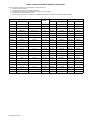
SECTION 8 − PARTS LIST
Figure 8-1. ST 44 Complete Assembly (Optional Equipment Shown)
956.142.672_C
. Hardware is common and
not available unless listed.
1
2
3
4
5
6
7
8
9
10
25
24
16
15
14
13
12
11
57
17
18
19
26
27
20
21
22
23
Fig. 8-2
28
29
30
31
32
33
34
35
36
37
38
39
40
41
42
56
55
54
53
52
51
50
49
48
47
46
45
43
44
58
40
Description
Part
No.
Dia.
Mkgs.
Item
No.
Figure 8−1. ST 44 Complete Assembly
Qty Basic Digital
1 000058427 Ring 1 1... ........... .. ................................................. .......
2 156032128 Spring 1 1... ........... .. ............................................... .......
3 156018033 Nut 1 1... ........... .. .................................................. .......
4 156009079 Washer 1 1... ........... .. .............................................. .......
5 156032064 Spring 1 1... ........... .. ............................................... .......
6 156009075 Washer, flat 1 1... ........... .. ........................................... .......
7 000186435 Hub 1 1... ........... .. ................................................. .......
8 287119 Washer,plastic 1 1... .............. .. ........................................ .......
9 057084128 Circuit Card, motor reed control 1 1... ........... .. ......................... .......
10 027112275 Weld cable, w/lugs 1 1... ........... .. .................................... .......

OM-216 655 Page 15
Description
Part
No.
Dia.
Mkgs.
Item
No. Qty Basic Digital
Figure 8−1. ST 44 Complete Assembly
11 556049403 Fitting, Quick Connect Water, Male Red 1... ........... .. ............................
12 556049404 Fitting, Quick Connect Water, Male Blue 1... ........... .. ............................
656043012 Cover Blanking Cap 2................. .. ...................................
13 056076216 Receptacle, dinse 1 1... ........... .. ..................................... .......
14 056076192 Receptacle, 14 pin 1 1... ........... .. ..................................... .......
15 GS1 056061042 Solenoid Valve, 24VAC 1 1... ... ... .. ................................. .......
16 CB1 056067188 Circuit Breaker, 5 A 1 1... ... ... .. .................................... .......
17 156034005 Latch 2 2... ........... .. ................................................ .......
18 116122319 Side panel 1 1... ........... .. ............................................ .......
19 156034004 Hinge 2 2... ........... .. ................................................ .......
20 000204326 Consumable Storage Box (Includes) 1 1... ........... .. ..................... .......
000151187 Latch 1 1................. .... .............................................. .......
21 195585 Handle Assy 1 1... .............. .. .......................................... .......
22 +156121022 Wrapper 1 1... .......... .. ............................................. .......
23 000178936 Label, warning general precautionary 1 1... ........... .. .................... .......
24 656026091 Hose, 6x11x570 red water 1... ........... .. ........................................
25 656026090 Hose, 6x11x570 blu water 1... ........... .. ........................................
26 116118168 Panel, rear 1 1... ........... .. ........................................... .......
27 117060014 Baffle Plate, centre 1 1... ........... .. .................................... .......
28 156005108 Support, spool 1 1... ........... .. ........................................ .......
29 000006393 Relay 2 2... ........... .. ................................................ .......
30 PC2 057095012 Circuit Card, digital meter board 1... ... ... .. ...................................
31 000134201 Circuit Card, spacer 4 4... ........... .. ................................... .......
32 PC1 057084124 Circuit Card, control board 1 1... ... ... .. .............................. .......
33 156005094 Circuit Card, support 1 1... ........... .. ................................... .......
34 S3 056093022 Switch, gas purge 1 1... .... ... .. ..................................... .......
35 S2 056093022 Switch, wire jog 1 1... .... ... .. ....................................... .......
36 S4 056067260 Switch, 2T 4T trigger latch 1 1... .... ... .. .............................. .......
37 S1 056067194 Switch, power on/off 1 1... .... ... .. ................................... .......
38 316029689 Nameplate, front, upper 1 1... ........... .. ................................ .......
39 ♦056076180 Receptacle, 7 pin (Includes) 1 1... ......... .. ............................ .......
656043035 Cover Blanking Cap, 22.5 mm 1 1................. .. ......................... .......
40 000207076 Knob, pointer 3 4... ........... .. ......................................... .......
41 556049402 Fitting, Quick Connect Water, Female Blue 1... ........... .. .........................
42 556049401 Fitting, Quick Connect Water, Female Red 1... ........... .. ..........................
41 656043012 Covering Blank Cap, 12.7 mm 1... ........... .. ..........................
42 656043012 Covering Blank Cap, 12.7 mm 1... ........... .. ..........................
43 *756005024 Flange, Euro adapter 1 1... .......... .. .................................. .......
43 656089035 Flange, US torch 1 1... ........... .. ...................................... .......
44 S4 ♦056067260 Switch, SPDT 10A/250V remote control (includes) 1 1... .... . .. ......... .......
♦656043031 Cover Blanking Cap, 10 x 13 mm 1 1............... .. ...................... .......
45 316029691 Nameplate,front, lower 1 1... ........... .. ................................. .......
46 116118167 Panel, front 1 1... ........... .. ........................................... .......
47 R1 056059182 Potentiometer, wire speed control 1 1... .... ... .. ....................... .......
48 000178937 Label, warning electric shock and pinch 1 1... ........... .. .................. .......
49 R2 056059182 Potentiometer, voltage control (includes) 1... .... ... .. ............................
656043033 Cover Blanking Cap, 9.7 mm 1................. .. ..........................
50 116005324 Motor Support 1 1... ........... .. ........................................ .......
51 R3, R4 056059277 Potentiometer 10.0k ohm Run In/Burn Back 2 2... .. . .. ............... .......
52 +116006130 Base 1 1... .......... .. ................................................ .......
53 656110012 Foot, rubber mount 4 4... ........... .. .................................... .......
54 656026084 Hose, gas braided 5x8,5x600 black 1 1... ........... .. ...................... .......
55 *V57052030 Euroadapter 1 1... .......... .. .......................................... .......
56 156090015 Guide, wire Inlet 1 1... ........... .. ....................................... .......
57 956142906 Nameplate, rear ST 44 1 1... ........... .. ................................. .......
58 956142486 Nameplate, potentiometer ST 44 1 1... ........... .. ........................ .......
To maintain the factory original performance of your equipment, use only Manufacturer’s Suggested
Replacement Parts. Model and serial number required when ordering parts from your local distributor.
+ When ordering a component originally displaying a precautionary label, the label should also be ordered.
* Euro torch models only.
♦ Optional

OM-216 655 Page 16
956.142.674_B
. Hardware is common and
not available unless listed.
11
11
10
10
14
15
18
13
15
17
3
4
28
27
27
31
33
19
21
22
23
24
15
16
26
20
32
7
16
16
26
26
12
33
15
24
23
22
21
19
9
30
29
34
8
26
16
6
5
3
2
1
25
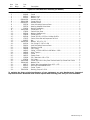
Figure 8-2. 4 Roll Wire Drive Assembly (All Models)
Page is loading ...
Page is loading ...
Page is loading ...
Page is loading ...
-
 1
1
-
 2
2
-
 3
3
-
 4
4
-
 5
5
-
 6
6
-
 7
7
-
 8
8
-
 9
9
-
 10
10
-
 11
11
-
 12
12
-
 13
13
-
 14
14
-
 15
15
-
 16
16
-
 17
17
-
 18
18
-
 19
19
-
 20
20
-
 21
21
-
 22
22
-
 23
23
-
 24
24


Miller MD272649D Owner's manual
- Category
- Welding System
- Type
- Owner's manual
- This manual is also suitable for
Ask a question and I''ll find the answer in the document
Finding information in a document is now easier with AI
Other documents
-
HobartWelders HANDLER 210 MVP Owner's manual
-
HobartWelders HANDLER 190 AND H100S4-10 GUN Owner's manual
-
-
Miller Electric SWLL-115 Owner's manual
-
-
-
-
-
-