
Operating Instructions
Reed sensor for bypass level indicators, model BT
EN
Reed Sensor for bypass level indicators model BT
Aluminium housing, bottom mounted
1208872/ 31.07.2018 EN

2 KSR KUEBLER Operating Instructions BT
EN
Reed sensor for bypass level indicators, model BT
© 2016 WIKA Alexander Wiegand SE & Co. KG
All rights reserved. / Alle Rechte vorbehalten.
WIKA® and KSR® are registered trademarks in various countries.
WIKA® and KSR® sind geschützte Marken in verschiedenen Ländern.
Prior to starting any work, read the operating instructions!
Keep for later use!
Vor Beginn aller Arbeiten Betriebsanleitung lesen!
Zum späteren Gebrauch aufbewahren!
KSR Kuebler Niveau-Messtechnik AG
Heinrich-Kuebler-Platz 1
69439 Zwingenberg am Neckar • Germany
Tel. +49 6263/87-0
Fax +49 6263/87-99
info@ksr-kuebler.com
www.ksr-kuebler.com
Gayesco-WIKA USA
229 Beltway Green Boulevard
Pasadena, Texas 77503
Tel. +1 713 475 0022
Fax +1 713 475 0011
info@wikahouston.com
www.wika.com

KSR KUEBLER Operating Instructions BT 3
Contents
1. General information 4
2. Design and function 5
3. Safety 6
4. Transport, packaging and storage 10
5. Commissioning, operation 11
6. Faults 15
7. Maintenance and cleaning 16
8. Dismounting, return and disposal 18
9. Specifications 19

4 KSR KUEBLER Operating Instructions BT
1. General information
The magnetic Level sensors described in the operating instructions have been
designed and manufactured using state-of-the-art technology. All components
are subject to stringent quality and environmental criteria during production.
Our management systems are certified to ISO 9001.
These operating instructions contain important information on handling the
instrument. Working safely requires that all safety instructions and work in-
structions are observed.
Observe the relevant local accident prevention regulations and general safety
regulations for the instrument’s range of use.
The operating instructions are part of the product and must be kept in the im-
mediate vicinity of the instrument and readily accessible to skilled personnel at
any time. Pass the operating instructions on to the next operator or owner of
the instrument.
Skilled personnel must have carefully read and understood the operating in-
structions prior to beginning any work.
The general terms and conditions contained in the sales documentation shall
apply.
Subject to technical modifications.
Further information:
Internet address: www.ksr-kuebler.com / www.wika.com
Relevant data sheet: BLR / LM 10.04

KSR KUEBLER Operating Instructions BT 5
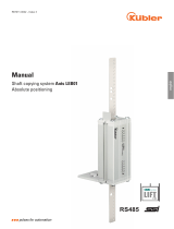
2. Design and function
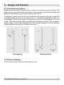
2.1 Functional description
Reed sensors series BT are used for continuous monitoring and recording of the
liquid level in connection with transmitters. They operate on the float principle with
magnetic transmission in a 3-wire potentiometer circuit.
A magnetic system built into the float actuates reed contacts, through the walls of
the bypass chamber and of the sensor tube, in a resistance measuring chain (po-
tentiometer). The float changes its height with the level of the medium it is moni-
toring. The measured resistance signal is proportional to the level. The measure-
ment voltage is very finely stepped due to the contact separation of the resistance
measuring chain and is thus virtually continuous.
Housing top
Housing bottom
2.2 Scope of delivery
Cross-check scope of delivery with delivery note.

6 KSR KUEBLER Operating Instructions BT
3. Safety
3.1 Symbols
DANGER!
... indicates an immediately hazardous situation which
might result in death or severe injuries if it is not avoided.
WARNING!
... indicates an potentially hazardous situation which might
result in death or severe injuries if it is not avoided.
CAUTION!
... indicates an potentially hazardous situation which might
result in light or minor injuries or property or environmental
damages if it is not avoided.
Information
... highlights useful tips and recommendations and infor-
mation for efficient and fault-free operation.
3.2 Proper intended use
Level sensors are solely intended for monitoring the liquid level of fluids.
The area of use is based on the technical performance limits and materi-
als.
The fluids must not be contaminated nor contain coarse particles nor
tend to crystallize. It must be ensured that the magnetic switch materi-
als that come into contact with the media are sufficiently resistant to the
monitored medium. Not suitable for dispersion, abrasive fluids, highly
viscous media and paints.
Compliance with the usage conditions specified in the operating instruc-
tions is required.
Do not operate the unit in direct proximity of ferro-magnetic environ-
ments (distance min. 50mm).
Do not operate the unit in direct proximity of strong electromagnetic
fields or in direct proximity of facilities that can be impacted by magnetic
fields (distance min. 1m).

KSR KUEBLER Operating Instructions BT 7
The level sensors must not be exposed to heavy mechanical strain (im-
pact, bending, vibration).
Compliance with the relevant safety regulations for the use is required.
Compliance with the technical specifications in these operating instruc-
tions is required. Improper use or operation of the unit outside the tech-
nical specifications requires immediate shut-down and inspection by an
authorized WIKA service technician.
Claims of any kind due to improper use are excluded.
DANGER!
When working on containers, there is a risk of poisoning or
suffocation. Work may only be performed using suitable
personal safety equipment (e.g. respiratory protection,
protective clothing, etc.).
An explosive atmosphere may develop in a container.
Measures must be taken to prevent sparking. Work in such
areas must be done by qualified personnel in accordance
with the relevant safety regulations and guidelines.

8 KSR KUEBLER Operating Instructions BT
3.3 Improper use
Any use that exceeds the technical performance thresholds or that is in-
compatible with the materials is considered improper use.
WARNING!
Injury due to improper use
Improper use of the unit can result in hazardous situations
and injuries.
Do not modify the unit without authorization.
Any use beyond the proper intended use or any other use is considered
improper use.
Do not use this unit in safety or emergency off equipment.
3.4 Responsibility of the operator
The unit is used in the industrial sector. The operator is therefore subject
to statutory obligations with respect to occupational safety.
Compliance with the safety instructions in these operating instructions and
the applicable safety, accident prevention and environmental protection
regulations for the area of use of the unit is required.
In order to safely work on the unit, the operator must ensure
the operating personnel is regularly trained in all matters pertaining to
occupational safety, first aid and environmental conservation and is fa-
miliar with the operating instructions and, in particular, the safety in-
structions contained therein
the unit is suitable for the application in accordance with the proper in-
tended use (check for improper use).
After check, improper use is excluded.

KSR KUEBLER Operating Instructions BT 9
3.5 Personnel qualification
WARNING!
Risk of injury due to insufficient qualifications
Improper use can result in significant personal injury and
property damages.
The activities described in these operating instructions
may only be performed by specialist technicians with the
following qualifications.
Specialist personnel
The specialist personnel authorized by the operator is capable of execut-
ing the described work and autonomously detect potential hazards due
their technical training, knowledge of measuring and control technology
and their experience and knowledge of country-specific regulations, appli-
cable standards and guidelines.
3.6 Personal safety equipment
The personal safety equipment serves to protect the technicians against
hazards that might impact the safety or health while working. When exe-
cuting the various tasks on and with the unit, the technicians must wear
personal safety equipment.
Comply with warning signs posted in the work area regarding per-
sonal safety equipment!
The required personal safety equipment must be provided by the operator.

10 KSR KUEBLER Operating Instructions BT
4. Transport, packaging and storage
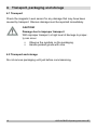
4.1 Transport
Check the magnetic Level sensor for any damage that may have been
caused by transport. Obvious damage must be reported immediately.
CAUTION!
Damage due to improper transport
With improper transport, a high level of damage to proper-
ty can occur.
Observe the symbols on the packaging.
Handle packed goods with care
4.2 Transport and storage
Do not remove packaging until just before commissioning.

KSR KUEBLER Operating Instructions BT 11
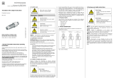
5. Commissioning, operation
Observe all instructions given on the shipment packaging for removing
the transportation safety devices.
Remove the magnetic Level sensor carefully from the packaging!
When unpacking, check all components for any external damage.
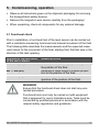
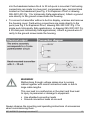
5.1 Functional check
Prior to installation, a functional test of the level sensor can be carried out
with a resistance measuring instrument and manual movement of the float.
The following table describes the measurements and the expected meas-
ured values for the movement of the float, starting from the float stop in the
direction of the tank opening.
Resistance measurement
of the wire colours
Measured value
BK ― BN (R1)
Resistance value rises proportionally with
the position of the float.
BU ― BN (R2)
Resistance value drops in inverse propor-
tion to the position of the float.
BK ― BU (Ri)
Resistance value remains constant, irre-
spective of the position of the float.
WARNING!
Ensure that the functional check does not start any unin-
tended processes.
Functional tests must only be carried out with equipment
that is approved for use in hazardous area. Tests must be
conducted by qualified personnel in accordance with the
relevant safety regulations and guidelines.

12 KSR KUEBLER Operating Instructions BT
5.2 Mounting
Normally, the reed sensor is pre-mounted on the bypass or on the top-
mounted level indicator. With this, please pay attention to the position of
the measuring range marking as well as the distance between the reed
sensor and the bypass chamber. The distance should be as low as possi-
ble.
5.3 Electrical connection
Warning!
Never open cover in hazardous areas while circuits
are energized. Follow all safety work procedures and
lock out circuits before servicing or inspection.
The electrical connection must only be made by qualified skilled per-
sonnel.
Wire the level sensor in accordance with the connection diagram of the
electrical output (see product label). The connection terminals are ap-
propriately marked.
Seal the cable gland at the connection housing.
Install a pour-seal (conduit seal) fitting within 18 inches of the housing
to prevent water from entering the housing and for compliance with the
National Electrical Code.
Transmitters with integral electronics (puck and/or display) must be
connected in a series loop with the readout or data acquisition device
and the power supply. Shielded cable must be used for noise immunity
and for Intrinsically Safe applications an agency approved safety barrier
must be installed. A ground wire must be provided and connected to the
ground block inside the housing.
To connect a transmitter with a built-in digital display, unscrew and re-
move the housing cover and carefully remove the plastic label from
around the display by grasping each side and pulling upwards. Remove
the digital display by carefully pulling up on two diagonal sides of the
display. The indicator is held in place by two banana plugs which plug

KSR KUEBLER Operating Instructions BT 13
into the baseboard where the 4 to 20 mA puck is mounted. Field wiring
connections are made to a two point, compression type, terminal block
located on the baseboard (see Fig. 2 for Explosion Proof or drawing
095-3201-001 Pg. 1 for Intrinsically Safe applications). Attach a ground
wire directly to the ground screw inside the housing.
To connect a transmitter without a built-in display, unscrew and remove
the housing cover. Field wiring connections are made directly to the
puck (see Fig 3 for Explosion Proof, drawing 095-3201-001 Pg. 2 for
single puck Intrinsically Safe applications, or drawing 095-3201-001 Pg.
4 for dual puck Intrinsically Safe applications). Attach a ground wire di-
rectly to the ground screw inside the housing.
WARNING!
Malfunctions through voltage spikes due to running
cables together with mains connection leads or due to
large cable lengths.
This can lead to a malfunction in the plant and thus lead
to injury to personnel or damage to equipment.
Use shielded connection leads
Ground connection leads at one end
Always observe the mounting and operating instructions of accessories
when commissioning them.

14 KSR KUEBLER Operating Instructions BT
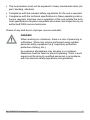
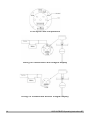
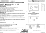
PCB layout and components
Wiring for transmitters with integral display
Wiring for transmitters without integral display

KSR KUEBLER Operating Instructions BT 15
6. Faults
The following table contains the most frequent causes of
faults and the necessary countermeasures.
Faults
Causes
Measures
No signal,
non-linear or
undefined
signal
Electrical connection
incorrect
See chapter 5.4 “Electrical
connection”. Check as-
signment with the aid of
the connection diagram.
Measuring chain defec-
tive
Return to the factory
Head-mounted transmit-
ter defective
Return to the factory
Head-mounted transmit-
ter adjusted incorrectly
Change settings acc. to
manual of head-mounted
transmitter or return to the
factory
CAUTION!
Physical injuries and damage to property and the
environment
If faults cannot be eliminated by means of the listed
measures, the instrument must be taken out of operation
immediately.
Ensure that there is no longer any pressure present
and protect against being put into operation
accidentally.
Contact the manufacturer.
If a return is needed, please follow the instructions
given in chapter 8.2 “Return”.

16 KSR KUEBLER Operating Instructions BT
7. Maintenance and cleaning
7.1 Maintenance
When used properly, the level sensors work maintenance-free. They must
be subjected to visual inspection within the context of regular mainte-
nance, however, and included in the vessel pressure test.
DANGER!
Work on vessels involves the danger of intoxication and
suffocation. No work is allowed to be carried out unless by
taking suitable personal protective measures (e.g. respira-
tory protection apparatus, protective outfit etc.).
Repairs must only be carried out by the manufacturer.
Perfect functioning of the level sensors can only be guar-
anteed when original accessories and spare parts are
used.

KSR KUEBLER Operating Instructions BT 17
7.2 Cleaning
CAUTION!
Physical injuries and damage to property and the en-
vironment
Improper cleaning may lead to physical injuries and dam-
age to property and the environment. Residual media in
the dismounted instrument can result in a risk to persons,
the environment and equipment.
Rinse or clean the removed instrument.
Sufficient precautionary measures must be taken.
1. Prior to cleaning the unit, properly disconnect it from the process and
the power supply.
2. Carefully clean the unit with a damp cloth.
3. Do not let electrical connections come into contact with moisture!
CAUTION!
Damage to property
Improper cleaning may lead to damage to the instrument!
Do not use any aggressive cleaning agents.
Do not use any pointed and hard objects for cleaning.

18 KSR KUEBLER Operating Instructions BT
8. Dismounting, return and disposal
WARNING!
Physical injuries and damage to property and the envi-
ronment through residual media
Residual media in the dismounted instrument can result in a
risk to persons, the environment and equipment.
Wash or clean the dismounted instrument, in order to
protect persons and the environment from exposure to
residual media.
8.1 Dismounting
Only disconnect the measuring instrument once the system has been de-
pressurised and the power disconnected!
8.2 Return
Wash or clean the dismounted magnetic Level sensor before returning
it, in order to protect personnel and the environment from exposure to
residual media.
Information on returns can be found under the heading
“Service” on our local website.
8.3 Disposal
Incorrect disposal can put the environment at risk.
Dispose of instrument components and packaging materials in an envi-
ronmentally compatible way and in accordance with the country-specific
waste disposal regulations.

KSR KUEBLER Operating Instructions BT 19
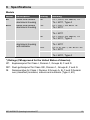
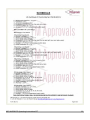
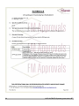
9. Specifications
Models
Model
Description
Rating
*)
Marking
BT
Reed level sensor
aluminium housing
NI
CL I, Div 2, GP ABCD, T4
Ta = 60°C, Type 4
BTX
Reed level sensor
aluminium housing
XP
CL I, Div 1, GP BCD T6
Ta = 60°C
DIP
CL II, III, Div 1, GP EFG T3C
Ta = 60°C
NI
CL I, Div 2, GP ABCD, T4
Ta = 60°C, Type 4
BTXI
Reed level sensor
aluminium housing
with indicator
XP
CL I, Div 1, GP BCD T6
Ta = 60°C
DIP
CL II, III, Div 1, GP EFG T3C
Ta = 60°C
NI
CL I, Div 2, GP ABCD, T4
Ta = 60°C, Type 4
*) Ratings (FM-approved for the United States of America)
XP: Explosionproof for Class I, Division 1, Groups B, C and D
DIP: Dust-ignitionproof for Class II/III, Division 1, Groups E, F and G
NI: Nonincendive for Class I, Division 2 Groups A, B, C and D hazard-
ous (classified) locations, indoors and outdoors (Type 4, 4X)

20 KSR KUEBLER Operating Instructions BT
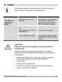
Type code
Field-No.
Code
Description
Basic type
1
BT
Reed level sensor, NI
BTX
Reed level sensor, XP, DIP, NI
BTXI
Reed level sensor with indicator, XP, DIP, NI
Resolution
2
aa
Resolution in mm (2 digits)
Length
3
bbbb
Length in inches (4 digits)
(1)
(2)
(3)
Type:
-
-
For further specifications see data sheet BLR and LM 20.02.
Page is loading ...
Page is loading ...
Page is loading ...
Page is loading ...
Page is loading ...
Page is loading ...
Page is loading ...
Page is loading ...
-
 1
1
-
 2
2
-
 3
3
-
 4
4
-
 5
5
-
 6
6
-
 7
7
-
 8
8
-
 9
9
-
 10
10
-
 11
11
-
 12
12
-
 13
13
-
 14
14
-
 15
15
-
 16
16
-
 17
17
-
 18
18
-
 19
19
-
 20
20
-
 21
21
-
 22
22
-
 23
23
-
 24
24
-
 25
25
-
 26
26
-
 27
27
-
 28
28


Ask a question and I''ll find the answer in the document
Finding information in a document is now easier with AI
Related papers
-
WIKA FLR-H tag:model:FLR-P tag:model:FLR-S Operating instructions
-
-
-
-
-
-
-
-
-
Other documents
-
Unbranded T3C-24-MV-30 Installation guide
-
Thermon SnoTrace KSR User guide
-
Lightolier IS:CS100 User manual
-
KSR LIGHTING KSRFRD381 Installation guide
-
 BD|SENSORS DAC 105K Operating instructions
-
 Kübler Ants LEB01 User manual
-
 KSR LIGHTING KS98102 User manual
-
Texas Instruments Using Position Manager BiSS-C Library on IDDK User guide
-
Comet MTP LW MISTING User manual
-
RS PRO 2348852 Float Switch User manual


