Dometic 3313214.029 630025 650015 Air Conditioner Mech 3311670 ADB Operating instructions
- Category
- Heat pumps
- Type
- Operating instructions
This manual is also suitable for

INSTALLATION & OPERATING
INSTRUCTIONS
REVISION A
Form No. 3313214.029 11/16
(French 3313215.026_A)
©2016 Dometic Corporation
LaGrange, IN 46761
RECORD THIS UNIT INFORMATION
FOR FUTURE REFERENCE:
Model Number
Serial Number
ADB Number
ADB Serial Number
Date Purchased
USA
SERVICE OFFICE
Dometic Corporation
1120 North Main Street
Elkhart, IN 46514
CANADA
Dometic Corporation
46 Zatonski, Unit 3
Brantford, Ontario
CANADA N3T 5L8
SERVICE CENTER &
DEALER LOCATIONS
Please Visit:
www.eDometic.com
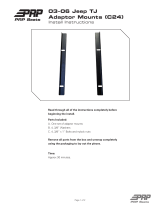
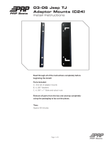
Note: Installation requires a #2 phillips screwdriver
with 9/32" maximum diameter x 1-1/4" minimum length.
630025.331
650015.30X
650015C35X
650015.80X
650015C85X
MODELS
Roof Top Unit
Description Model Use With Air Distribution Box
Model Control Electric Heat
Heat Pump 630025
650015
3311670.XXX Integral Mechanical N/A
This manual must be read and
understood before installation,
adjustment, service, or mainte-
nance is performed. This unit must
be installed by a qualied service
technician. Modification of this
product can be extremely hazard-
ous and could result in personal
injury or property damage.
Lire et comprendre ce manuel avant de
procéder à l’installation, à des réglages,
de l’entretien ou des réparations.
L’installation de ce produit doit être
effectuée par un réparateur qualié.
Toute modication de ce produit peut
être extrêmement dangereuse et
entraîner des blessures ou dommages
matériels.
Read these instructions carefully. These
instructions MUST stay with this product.

2
GENERAL INFORMATION
A. Product features or specications as described or il-
lustrated are subject to change without notice.
B. This heat pump (hereinafter referred to as the "unit")
is designed for:
1. Installation on a recreational vehicle during or af-
ter the time the vehicle is manufactured.
2. Mounting on the roof of a recreational vehicle.
3. Roof construction with rafters/joists on minimum
of 16 inch centers.
4. Minimum of 1.00 inch and maximum of 5.5 inches
distance between roof to ceiling of recreational
vehicle.
C. The ability of the air conditioner to maintain the de-
sired inside temperature depends on the heat gain of
the RV.
Some preventative measures taken by the occupants
of the RV can reduce the heat gain and improve the
performance of the air conditioner. During extremely
high outdoor temperatures, the heat gain of the RV
may be reduced by:
1. Parking the RV in a shaded area
2. Using window shades (blinds and/or curtains)
3. Keeping windows and doors shut or minimizing
usage
4. Avoiding the use of heat producing appliances
Operation on High Fan/Cooling mode will give optimum
or maximum efciency in high humidity or high outside
temperature.
Starting the air conditioner early in the morning and giving
it a "head start" on the expected high outdoor ambient will
greatly improve its ability to maintain the desired indoor
temperature.
For a more permanent solution to a high heat gain, ac-
cessories like Dometic outdoor patio and window awnings
will reduce heat gain by removing the direct exposure to
the sun. They also add a nice area to enjoy company dur-
ing the cool of the evening.
D. Condensation
Note: The manufacturer of this unit will not be responsible
for damage caused by condensed moisture on ceilings or
other surfaces. Air contains moisture and this moisture
tends to condense on cold surfaces. When air enters the
RV, condensed moisture may appear on the ceiling, win-
dows, metal parts, etc. During normal operation this unit
removes moisture from the air. Keeping doors and win-
dows closed when this air conditioner is in operation will
minimize condensed moisture on cold surfaces.
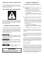
IMPORTANT SAFETY INSTRUCTIONS
This manual has safety information and instruc-
tions to help users eliminate or reduce the risk
of accidents and injuries.
RECOGNIZE SAFETY INFORMATION
This is the safety alert symbol. It is used to alert
you to personal injury hazards. Obey all safety
messages that follow this symbol to avoid pos-
sible injury or death.
UNDERSTAND SIGNAL WORDS
A signal word, when used with the safety alert
symbol, will identify a safety hazard and its level
of risk for personal injury. A signal word, without
the safety alert symbol, will be used for property
damage messages only.
WARNING indicates a hazard-
ous situation which, if not avoided, could result
in death or serious injury.
CAUTION, used with the safe-
ty alert symbol, indicates a hazardous situation
which, if not avoided, could result in minor or
moderate injury.
NOTICE is used to address
practices not related to personal injury.
Read and follow all safety information and
instructions to avoid personal injury.

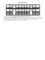
3
Model No. Nominal
Capacity
(BTU HR)
Cooling
Electrical
Rating
120 VAC
60Hz. 1PH
Compressor
Cooling Rated
Load Amps
Compressor
Locked
Rotor
Amps
Fan Motor
Rated Load
Amps
Fan Motor
Locked
Rotor
Amps
Refrigerant
R-22
(Oz.)
Minimum
Wire Size*
12 AWG
Copper
Up to 24'
AC Circuit
Protection
***Installer
Supplied
Minimum
Generator
Size**
1 Unit / 2 Units
630025.331 13,500 12.4 61.0 3.5 10.0 23.5 20 Amp 3.5 KW / 5.0 KW
SPECIFICATIONS
* For wire length over 24 ft., consult the National Electric Code for proper sizing.
** Dometic Corporation gives GENERAL guidelines for generator requirements. These guidelines come from experiences
people have had in actual applications. When sizing the generator, the total power usage of your recreational vehicle
must be considered. Keep in mind generators lose power at high altitudes and from lack of maintenance.
*** CIRCUIT PROTECTION: Time Delay Fuse or Circuit Breakers Required.
Model No. Nominal
Capacity
(BTU HR)
Cooling
Electrical
Rating
120 VAC
60Hz. 1PH
Compressor
Cooling Rated
Load Amps
Compressor
Locked
Rotor
Amps
Fan Motor
Rated Load
Amps
Fan Motor
Locked
Rotor
Amps
Refrigerant
R-410A
(Oz.)
Minimum
Wire Size*
12 AWG
Copper
Up to 24'
AC Circuit
Protection
***Installer
Supplied
Minimum
Generator
Size**
1 Unit / 2 Units
650015.30X 13,500 12.5 61.0 3.3 8.5 25.0 20 Amp 3.5 KW / 5.0 KW
650015C35X 13,500 12.5 61.0 3.3 8.5 25.0 20 Amp 3.5 KW / 5.0 KW
650015.80X 13,500 13.1 63.0 2.6 8.5 24.0 20 Amp 3.5 KW / 5.0 KW
650015C85X 13,500 13.1 63.0 2.6 8.5 22.0 20 Amp 3.5 KW / 5.0 KW

4
A. Precautions
INSTALLATION INSTRUCTIONS
1. Read installation and operating instructions care-
fully before attempting to start this unit installa-
tion.
2. Dometic Corporation will not be liable for any
damages or injury incurred due to failure in fol-
lowing these instructions.
3. Installation MUST comply with the National Elec-
trical Code ANSI/NFPA-70 and CSA Standard
C22.1 (latest edition) and any State or Local
Codes or regulations.
4. Do NOT add any devices or accessories to this
unit except those specically authorized in writing
by Dometic Corporation.
5. This equipment MUST be serviced by qualied
personnel and some states require these people
to be licensed.
B. Choosing Proper Location For The Unit
This unit is specically designed for installation on the
roof of a recreational vehicle (RV). When determining
your cooling requirements, the following should be
considered:
• Size of RV;
• Window area (increases heat gain);
• Amount of insulation in walls and roof;
• Geographical location where the RV will be used;
• Personal comfort level required.
1. Normal locations-The unit is designed to t over
an existing roof vent opening.
2. Other locations-When no roof vent is available or
another location is desired, the following is rec-
ommended:
a. For one unit installation: The unit should be
mounted slightly forward of center (front to
back) and centered from side to side.
b. For two unit installations: Install one unit 1/3
and one unit 2/3's from front of RV and cen-
tered from side to side.
It is preferred that the unit be installed on a relatively at
and level roof section with the RV parked on a level sur-
face but up to a 8° tilt is acceptable.
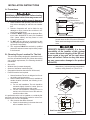
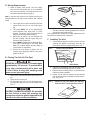
3. After Location Has Been Selected
a. Check for obstructions in the area where unit
will be installed. See FIG. 1.
b. The roof must be designed to support 130
pounds when the RV is in motion. Normally a
200 lb. static load design will meet this require-
ment.
c. Check inside the RV for air distribution box
obstructions. (i.e. door openings, room dividers,
curtains, ceiling xtures, etc.) See FIG. 2.
9-1/2"
40"
29"
FIG. 1
Dimensions Are Nominal
Center Line
Of Unit
Dimensions Are Nominal
Keep These Areas
Free Of Obstructions
14-1/4" x 14-1/4"
(± 1/8") Opening
Front
12"
4"
4"
3"
14-1/4" x 14-1/4" (± 1/8")
Opening
3"
5-29/64"
2-15/16"
4-15/16"
9-3/16"
Air
Duct
5-1/8" 6"
2-3/4"
(overall
depth)
20"
25"
Air Distribution Box
View From Above
Front
Front
FIG. 2
Dimensions Are Nominal
Dimensions Are Nominal
PERSONAL INJURY HAZARD. Failure to obey
these installation instructions may cause seri-
ous personal injury and/or property damage.
PROPERTY DAMAGE HAZARD. It is the re-
sponsibility of the installer of this system
to ensure structural integrity of the RV roof.
Never create a low spot on the roof where
water will collect. Failure to obey this warn-
ing may cause water damage to the product
and the RV.

5
C. Roof Preparation
1. Opening Requirements - Before preparing the
ceiling opening, read all of the following instruc-
tions before beginning the installation.
If a existing roof vent opening will not be used
a 14-1/4" x 14-1/4" (± 1/8") opening must be cut
through the roof and ceiling of the RV. This open-
ing must be located between the roof reinforcing
members.
The 14-1/4" x 14-1/4" (± 1/8") opening is part of
the return air system of the unit and MUST be
nished in accordance with ANSI A119.2.
2. Roof Vent Removal
a. Unscrew and remove the roof vent.
b. Remove all caulking compound around open-
ing.
c. Seal all screw holes and seams where the
roof gasket will be located. Use a good grade
of all weather sealant.
d. If the opening exceeds 14-3/8" x 14-3/8", it
will be necessary to re-size the opening to
14-1/4" x 14-1/4" (± 1/8").
e. If the opening is less than 14-1/8" x 14-1/8",
it must be enlarged to 14-1/4" x 14-1/4" (±
1/8").
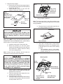
3. New opening-(installations other then vent open-
ings)
a. Mark a 14-1/4" x 14-1/4" (±1/8") square on
the roof and carefully cut the opening.
b. Using the roof opening as a guide, cut the
matching hole in the ceiling.
c. The opening created must be framed to pro-
vide adequate support and prevent air from
being drawn from the roof cavity. Framing
stock 3/4" thick or more must be used. Re-
member to provide an entrance hole for pow-
er supplies at front of opening. See FIG. 3.
Do Not Cut Roof
Structure Or
Rafters
Good-Rafters
Supported By
Cross Beams
Good Location-
Between Roof
Rafters
Frame Opening So It
Won't Collapse When
Bolting Down Unit
Leave Access For Power
Supply Wiring
15" Min. At
Front Of
Opening
3/4" Min.
FIG. 3
SHOCK HAZARD. There may be electrical
wiring between the roof and the ceiling. Dis-
connect 120 VAC power supply and the posi-
tive (+) 12 VDC terminal at the supply battery.
Failure to obey this warning may cause death
or severe personal injury.
PROPERTY DAMAGE HAZARD. It is the re-
sponsibility of the installer of this system
to ensure structural integrity of the RV roof.
Never create a low spot on the roof where
water will collect. Failure to obey this warn-
ing may cause water damage to the product
and the RV.

6
4. Place the air distribution box kit inside the RV.
This box contains mounting hardware for the unit
and will be used inside the RV.
This completes the outside work. Minor adjustments can
be done from inside the RV if required.
F. Installing The Unit
1. Check gasket alignment of the unit over the roof
opening and adjust if necessary. Unit may be
moved from below by slightly lifting. See FIG. 5.
2. Remove air distribution box and mounting hard-
ware from the air distribution box kit carton.
3. Remove wire tie holding center of rear aluminum
bracket to plastic template.
4. Reach up into return air opening of the unit and
pull the unit electrical cord down for later connec-
tion. See FIG. 6.
D. Wiring Requirements
1. Route a copper, with ground, 120 VAC supply
wire from the time delay fuse or circuit breaker
box to the roof opening. The proper size wire can
be determined from chart on page 3.
Note: If vent fan was removed, the existing wire may be
used provided it is of proper size, location, and correctly
fused.
a. This supply wire must be located in the front
portion of the 14-1/4" x 14-1/4" (±1/8") open-
ing.
b. The power MUST be on an appropriately
sized separate time delay fuse or circuit
breaker. The proper size protection can be
determined from the chart on page 3.
c. Make sure at least 15" of wire extends into
the roof opening. This will insure easy con-
nection at the junction box.
d. Wiring MUST comply with the National Elec-
trical Code ANSI/NFPA-70 and CSA Stan-
dard C22.1 (latest edition) and any State or
Local Codes or regulations.
e. Protect the wire where it passes into the
opening with approved method. See para-
graph "d" above.
E. Placing The Unit On The Roof
1. Remove the unit from the carton and discard car-
ton.
2. Place the unit on the roof.
3. Lift and place the unit over the prepared open-
ing using the gasket on the unit as a guide. See
FIG. 4.
FIG. 6
Reach Up Into The Return Air Opening
And Pull Down The Unit Electrical Cord
Lift And Place
Do Not Slide
FIG. 4
FRONT
Center Unit From Below
Roof Gasket
FIG. 5
PERSONAL INJURY HAZARD. This unit weighs
approximately 100 pounds. To prevent back
injury, use a mechanical hoist to place unit
on roof. Failure to obey this warning could
cause severe personal injury.
PROPERTY DAMAGE HAZARD. Do not slide
the unit. Failure to obey this warning may
damage the neoprene gasket attached to the
bottom and create a leaky installation.

7
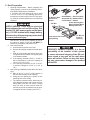
5. Base Pan Duct Adapter.
a. Remove the liner from the foam tape and posi-
tion on the base so screw hole and air openings
are aligned. See FIG. 7.
b. Install provided screw to help hold duct
adapter to base pan if desired.
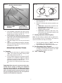
FIG. 10
Start 3 Mounting
Bolts By Hand
Trim Duct 1/2" to
1 " Below Ceiling
Template
Ceiling
Template
Mounting
Bolt
Mounting Bolt
Front
Do Not Disturb
Thermostat Bulb
c. Connect white to white; black to black; and
green to green or bare copper wire using ap-
propriate size connectors.
d. Tape the connectors to the supply wire to as-
sure they don’t vibrate off.
e. Push the wires into the box.
f. Insert back edge of cover under tabs and snap
control box cover into place. Secure cover with
screw provided. See FIG. 8.
9 Pin Connector
FIG. 9
Control Box
SHOCK HAZARD. Disconnect 120 VAC. Fail-
ure to obey this warning could create a shock
hazard causing death or severe personal
injury.
SHOCK HAZARD. This product is equipped
with a 3 wire (grounded) system for protection
against shock hazard. Make sure that the unit
is wired into a properly grounded 120 VAC
circuit and the polarity is correct. Failure to
do so could result in death, personal injury
or damage to the equipment.
FIG. 8
Snap Cover
In Place Af-
ter Wires Are
Connected
Install Screw
Return Air
Opening
Discharge
Opening Place
Flange Of Duct
On RH Side When
Facing Front
Front
Screw
FIG. 7
Base Pan
Duct Adapter
6. 120 VAC Power Supply Connection
Note: Wiring MUST comply with National Electrical Code
ANSI/NFPA-70 and CSA Standard C22.1 (latest edition)
and any State or Local Codes or regulations.
a. Install the strain relief in the junction box.
b. Route the previously run 120 VAC power
supply wire through the strain relief and into
the junction box. Tighten connector making
sure not to damage wires.
Note: Connect wiring per schematic with UL listed wire
connectors for size of wire being connected.
7. Ceiling template installation.
Note: The large center hole in the ceiling template goes
to the rear. Insure that the thermostat bulb is not moved
during installation.
a. Plug the nine pin cord into the control box on
the ceiling template. See Fig. 9.
b. Start each mounting bolt by hand before
tightening any of them. The threaded inserts
in the base pan can be seen to aid in starting
the bolts.
i. This installation uses a 3 bolt pattern,
one in the rear center and two in the front
corners. See Fig. 10.

8
FIG. 11
Install 2 Screws In Tabs
Duct Adapter
Screw Holes
Must Line Up
If Necessary
Rotate 1/2 Turn
Fit Duct
Adapter
Inside Duct
G. Air Distribution Box Installation
Important: The inner walls of the ADB go inside the
walls of the ceiling template during installation.
1. Working from the rear looking forward with the
rear tipped down, place the air distribution box in-
ner walls against the inside of the ceiling template
walls. Slide the air distribution box backwards un-
til it touches the template. Raise the air distribu-
tion box to the ceiling. See FIG. 12.
2. Push up on the ADB at the locations indicated by
the paper labels to engage the snap locks. There
will be a quiet click heard when each latch en-
gages. See FIG. 12.
3. Hold the air distribution box to the ceiling with one
hand and install two coarse threaded 3.5 mm X 19
mm sharp pointed screws in the location shown in
FIG. 13.
4. Auxiliary screws may be installed at the locations
shown. These are NOT required to secure the
ADB to the template, but may be desired for aes-
thetic purposes in some ceiling geometries. See
FIG. 13.
FIG. 12
Position
ADB Walls
Inside And
Against End
Of Template
Walls
Raise Back
End Of ADB
To Ceiling
Push Here To Engage
Latches, Then Remove Labels
8. Template/Duct connector
a. Pull duct down through template opening.
b. Cut the duct 1/2"-1" below template opening.
See Fig. 10.
c. Align the template duct adapter with the tem-
plate duct hole making sure the screw holes
line up (if not rotate 1/2 turn). Insert template
duct adapter into duct. Leave one loop of
duct wire below the duct adapter groove. Do
not insert tabs inside of the duct.
d. Snap duct adapter into template and install 2
screws through the duct adapter tabs into the
ceiling template. See Fig. 11.
• Evenly tighten the bolts to a torque
of 40 to 50 inch pounds. This will
compress the roof gasket to ap-
proximately 1/2". The bolts are self
locking so further tightening is not
necessary. See FIG. 10.
PROPERTY DAMAGE HAZARD. If bolts are
left loose there may not be an adequate roof
seal or if over tightened, damage may occur
to the unit base or ceiling template. Tighten
to torque specications listed in this manual.

9
FIG. 14
Colder
5. Filter installation. Slide lters into slots in air dis-
tribution box. The outward curved side of the lter
handle faces the ceiling. See FIG. 13.
6. Knob installation. Install the two knobs provided
on the ends of the thermostat and selector switch
shafts. Align slot in knob with alignment post on
shaft and push into position.
7. The power supply to the unit may now be turned
"ON".
8. Your unit is now installed and ready for operation.
Read the following operating instructions before
attempting to run the unit.
Auxiliary Screw Locations
Auxiliary Screw
Locations
FIG. 13
Install 2 Primary
Mount Screw First
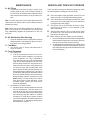
OPERATING INSTRUCTIONS
A. Controls
1. The selector switch has 10 positions including
"OFF". This controls fan speed, heating mode,
and cooling modes. See FIG. 14.
2. The thermostat controls the compressor ON/OFF
operation for a temperature range from approxi-
mately 65° F. to 90° F. at the ADB inlet, depend-
ing on the knob position. See FIG. 14.
The blower runs continually at the speed select-
ed.
Important: When the unit is turned on and the ther-
mostat calls for cooling or heating, the compressor
will start. After shutting the unit down manually by
either the selector switch or the thermostat, always
wait 2-3 minutes before turning on the unit. This al-
lows the refrigerant pressures in the unit system to
equalize so the compressor may start.
B. Cooling Operation (Blue Graphic)
1. Set the thermostat at the desired temperature
level. See FIG. 14.
2. Select the cooling mode that best satises your
needs:
a. HIGH COOL: Selected when maximum cool-
ing and dehumidication required.
b. MEDIUM COOL: Selected when normal or
average cooling required.
c. LOW COOL: Selected to main room at de-
sired comfort level. Normally this speed used
for night time operation.
C. Heating Operation (Red Graphic)
Note: The heat modes of operation will not replace a fur-
nace for heating your RV in cold weather. The intent is to
remove the chill on cool days or mornings.
1. Turn the selector switch to "HEAT" mode that
best satises your needs. See FIG. 14.
2. Set thermostat to the desired temperature level.
D. Fan Operation (Gray Graphic)
1. This will circulate the air in the RV without cooling
or heating. Turn the selector switch to the "FAN"
mode that best satises your needs.
E. "OFF" Position ( )
Gray Graphic
Fan
Red Graphic
Heating
Blue Graphic
Cooling

10
SERVICE-UNIT DOES NOT OPERATE
If your unit fails to operate or operates improperly, check
the following before calling your service center.
A. If RV connected to motor generator, check to be sure
motor generator is running and producing power.
B. If RV connected to power supply by a land line, check
to be sure line is sized properly to run unit load and it
is plugged into power supply.
C. Check your fuse or circuit breaker to see if it is open.
Insure fuse is not burnt, or circuit breaker is "ON"
and not activated.
D. After the above checks, call your local service center
for further help. This unit must be serviced by quali-
ed service personnel only.
E. When calling for service, always give the following:
1. Unit model and serial number found on identication
label located on base pan of unit bottom. (Remove
lter and view through network of holes)
2. Air distribution box model and serial number found
on rating plate located on ceiling template. Observe
this rating plate through the air distribution box right
side vent opening.
MAINTENANCE
A. Air Filters
1. Periodically (a minimum of every 2 weeks of op-
eration) slide out the return air lters located on
the end of the air distribution box. Wash the lters
with soap and warm water, let dry and then rein-
stall.
Note: To insure easy future removal the lters need to be
replaced with the domed side of their handle positioned
towards the ceiling.
Note: Never run the unit without both return air lters in
place. This will plug the unit evaporator coil with dirt and
may substantially degrade the performance of the unit
over time.
B. Air Distribution Box Housing
1. Clean air distribution box housing with a soft cloth
dampened with a mild detergent. Never use furni-
ture polish or scouring powders.
C. Fan Motor
1. The blower motor is factory lubricated and re-
quires no service.
D. Frost Formation
1. On Cooling Coil
a. Frost on a small portion of the coil is not un-
usual. Under certain conditions, ice may form
on the evaporator coil. This is indicated by
very cold output at very low air speed and the
icing can be seen through the air inlet holes
with the lters removed. If this should occur,
inspect the lter and clean if dirty. Make sure
air vents are open and not obstructed. Units
have a greater tendency to frost when the out-
side temperature is relatively low. This may be
prevented by adjusting the thermostat control
knob to a warmer setting (counter clockwise).
Should frosting continue, operate on any fan
ONLY setting until the cooling coil is free of
frost; then resume normal operation. If frost
condition persist, contact your local service
center for assistance.
2. On Outdoor Coil While Heating
a. Operation at low outdoor temperatures causes
low coil temperatures. This can result in ice
forming on the out door coil in certain condi-
tions. This is indicated by reduced heat output
and could fully stop fan rotation in extreme
conditions. To avoid this the system controls
turn off the compressor if out door temperature
drops below 42° F. and returns heating when
the temperature raises 5° F.

11
Unit Wiring Diagram
CAP
PASSED
BLK
1
BLK OR PRP
VALVE
WHT
COMPRESSOR
WHT
START
RED OR PNK
PTCR
(OPT)
RED
1
WHT
WHT
FAN
C
HERM
CONNECTOR
RED
PRP
WHT
2
IN-LINE
YEL
RUN CAP
AMBIENT
BLK OR WHT/PRP
3
2
O.L.
GRN/YEL
RED
RED
9 PIN CONN
YEL
3310429.026
9
7
BLU
8
3
4
BLK
6
MOTOR
GRN/YEL
BRN
DIELECTRIC
SWITCH
BLU
R
WHT
C
S
5
REVERSING
WHT/PNK OR
Air Distribution Box Wiring Diagram
9a
+=
86(&233(5
&21'8&7256
21/<
),(/':,5,1*
)$&725<:,5,1*
6:,7&+
527$5<
5('
%/.
&211(&725)520
522)81,7
&
/
7+(50267$7
%/8
+
/
&
%/8
%/.
*5<
<(/
*51<(/
*51<(/
353
%/.
:+7
+
WIRING DIAGRAM
-
 1
1
-
 2
2
-
 3
3
-
 4
4
-
 5
5
-
 6
6
-
 7
7
-
 8
8
-
 9
9
-
 10
10
-
 11
11


Dometic 3313214.029 630025 650015 Air Conditioner Mech 3311670 ADB Operating instructions
- Category
- Heat pumps
- Type
- Operating instructions
- This manual is also suitable for
Ask a question and I''ll find the answer in the document
Finding information in a document is now easier with AI
Related papers
-
Dometic 3312501.012 640312 640315 3310741 Integral Mechanical ADB Operating instructions
-
-
-
Dometic Roof Top Unit Used Operating instructions
-
-
-
-
Dometic 3314850, Blizzard NXT Installation guide
-
-
Other documents
-
Voyager Advent Air Owner's manual
-
Duo-Therm 600315.326 Installation guide
-
Furrion FACR15SA-PS User manual
-
Munchkin Brica Smart Shade User manual
-
-
-
Advent AC135HP Operating instructions
-
 PRP Seats Seat Adapter Brackets Installation guide
-
 PRP Seats C23 Installation guide
-
 PRP CF Moto 13 User manual


