Bell'O 8260DB User manual

Category
Flat panel wall mounts
Type
User manual

This manual is also suitable for

1
English
Introduction
Congratulations on your decision to mount your TV with a TV Wall Mounting Kit For Dummies. The
enclosed mounting bracket was engineered and designed by Bell’O International Corporation using the
latest computer-aided design and stress-analysis software to ensure safety and durability when installed
according to the instructions. It has been further tested and Listed by Underwriters Laboratories.
About This Manual
Mounting your TV on the wall can seem like an overwhelming task. This handy For Dummies
®
guide takes you
through the process step-by-step to ensure the proper installation of your mount. Before starting this project, be
sure to read the entire instruction manual and watch the included installation DVD for a complete
demonstration. If at any time you are unclear about the directions and believe you need further assistance,
contact the Bell’O
®
installation experts at 888-779-7781 from 9am 5pm EST.
Icons Used in This Book
Don’t be alarmed by the bomb in the icon. We just want to
get your attention because making an error could be costly.
This is not really very technical stuff, just some details you
need to really pay attention to.
Foolish Assumptions
Although our easy-to-install mounts and instructions simplify the process, mounting your TV still requires
great care. We assume you’re someone who, at minimum, has done odd jobs around the house and has
some basic tools. You don’t need to be a master carpenter or electrician to install this mount. With that
said, if at any time you feel that you are uncertain or uncomfortable with doing the installation yourself,
don’t hesitate to call on a handyman or professional contractor/installer.
2
English
NEVER exceed the maximum load capacity of:
TV Wall Mount 8260: 65 lbs (30 kg)
TV Wall Mount 8265: 50 lbs (23 kg)
Precautions!
This mounting bracket was designed to be installed and utilized ONLY as specified
in this manual. Bell’O International Corporation will not be responsible for failure
to assemble as directed or for the improper assembly, use, or handling of this
product.
Improper installation of this product may cause damage or serious injury.
Bell'O International Corporation cannot be liable for direct or indirect damage or
injury caused by incorrect mounting, incorrect use, or incorrect assembly.
If the mounting bracket will be attached to any structure other than those
specified in this manual, only a licensed professional contractor/installer should
perform this installation. The supporting structure must support, at minimum, four
times the combined weight of the mounting bracket and TV. It is the responsibility
and liability of the installer to ensure the suitability of the supporting structure.
This product should NEVER be mounted to metal framing studs.
Check carefully to ensure that there are no missing or damaged parts.
Never use defective parts. If any parts are damaged or missing, call Bell'O
International Corporation at 888-779-7781 and parts will be shipped directly to
purchaser. Please contact Bell’O International Corp. before attempting to return
products to the point of purchase.
Specifications are subject to change without notice.
The maximum weight of your television cannot exceed the maximum weight rating of
your mount or any attached Bell'O
®
UL listed adapters sold separately, whichever is
lower.
3
English
Parts Included in This Kit
(IG) Installation Guide
& DVD,
Quantity: 1 each
(IT) Installation
Template, Quantity: 1
(MP) Monitor Plate
Quantity: 1
Installation Video for
Bell’O TV Wall Mounting Kits
©
J
a
n
u
a
r
y
2
0
0
7
B
e
l
l
'
O
I
n
t
e
r
n
a
t
i
o
n
a
l
C
o
r
p
o
r
a
t
i
o
n
C
o
n
t
e
n
t
s
o
f
t
h
i
s
d
i
s
c
a
r
e
c
o
p
y
r
i
g
h
t
e
d
a
n
d
a
r
e
n
o
t
f
o
r
r
e
p
r
o
d
u
c
t
i
o
n
o
r
d
i
s
t
r
i
b
u
t
i
o
n
w
i
t
h
o
u
t
w
r
i
t
t
e
n
p
e
r
m
i
s
s
i
o
n
f
r
o
m
B
e
l
l
O
I
n
t
e
r
n
a
t
i
o
n
a
l
C
o
r
p
A
l
l
d
e
s
i
g
n
s
a
n
d
i
m
a
g
e
s
a
r
e
p
r
o
p
e
r
t
y
o
f
B
e
l
l
O
I
n
t
e
r
n
a
t
i
o
n
a
l
C
o
r
p
A
l
l
d
e
s
i
g
n
s
a
r
e
p
a
t
e
n
t
e
d
o
r
p
a
t
e
n
t
p
e
n
d
i
n
g
a
n
d
a
r
e
s
u
b
j
e
c
t
t
o
c
h
a
n
g
e
w
i
t
h
o
u
t
n
o
t
i
c
e
A step-by-step guide for
mounting your flat panel
TV safelyand easily!
Wileythe Wiley logo ForDummies
theDummiesMan logo and
relatedtrademarks or registered
trademarksofJohn Wiley & Sons Inc
and/oritsaffiliates Usedby license
Video:701
BellO International Corp.
711Ginesi Drive
Morganville,NJ 07751
(A)
M4 x
12mm TV
Mounting Screw, Quantity: 6
(B)
M4 x
22mm TV
Mounting Screw, Quantity: 6
(C)
M4 x
30mm TV
Mounting Screw, Quantity: 6
(SS)
M4 x
8mm
Security Screw, Quantity: 2
(Z)
Plastic Finishing Caps,
Quantity: 2
(AP) 8190 Adapter Plates,
Quantity: 1A, 1B
A
B
(AG) M5 x 6mm
Adapter Screw,
Quantity: 4
(F) M4/M5 Washer,
Quantity: 10
(8265)
(8260)
(EA) Extension Arm
Quantity: 1
Parts Included in This Kit (continued)
4
English
(D) M4/M5 Short
Spacer, Quantity: 6
(E) M4/M5 Long
Spacer, Quantity: 6
(Q) M6/M8 Short
Spacer, Quantity: 4
(P) M6/M8 Long
Spacer, Quantity: 4
(S) M6/M8 Washer,
Quantity: 4
(R) M4/M5 Washer,
Quantity: 4
(G) M5 x 12mm TV
Mounting Screw, Quantity: 6
(H) M5 x 22mm TV
Mounting Screw, Quantity: 6
(I) M5 x 30mm TV
Mounting Screw, Quantity: 6
(J) M6 x 14mm TV
Mounting Screw, Quantity: 4
(K) M6 x 25mm TV
Mounting Screw, Quantity: 4
(L) M6 x 35mm TV
Mounting Screw, Quantity: 4
(M) M8 x 20mm TV
Mounting Screw, Quantity: 4
(N) M8 x 30mm TV
Mounting Screw, Quantity: 4
(O) M8 x 40mm TV
Mounting Screw, Quantity: 4
5
Parts Included in This Kit (continued)
English
(WT) Wire Management
Ties, Quantity: 6
TOGGLER
®
brand ALLIGATOR
®
SOLID-WALL ANCHORS are patented under one or more of US Patent numbers 5,161,296 and 5,938,385; and foreign
counterparts thereof and of 4,752,170. Other patents pending. TOGGLER and ALLIGATOR are worldwide registered trademarks of Mechanical Plastics Corp.
(Y)
Allen Key Tool,
Quantity: 1
(U) TOGGLER
®
brand AF8
ALLIGATOR
®
Anchor, Quantity: 2
(T) #14 X 65mm Lag Bolt, Quantity: 2
Tools You Will Need
Phillips-head
Screwdriver
Stud Finder Drill Drill Bit Pencil
Tape Measure Masking Tape
Wood 5/32" (4mm)
or Masonry 5/16" (8mm)
Level
6
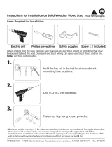
Getting ready to hang the TV
The Monitor Plate (MP) was shipped pre-installed to the Extension Arm
(EA). Before you begin, remove the two Security Screws (SS) as shown in
Figure 1 and separate the two components. Do not throw out the security
screws because you will need them later in the installation process.
Select the location where you want to mount the TV. Clear the area of all
furniture and electronics. You will need some elbow room to mount the
TV. You also want to make sure that your electronic devices are unplugged,
covered, and out of way because you are about to start drilling holes, and
that is likely to make dust. You will also need to leave space that you can
use to mount the monitor plate onto the TV.
Your TV may have come with a stand installed. If it did, it is okay to
leave it on for now as long as it does not interfere with the monitor plate
installation. If not, you need to determine the best way to hold or rest your TV safely so
you can attach the monitor plate. Placing the TV face-down can damage the fragile screen
or decorative frame. You may want to get a friend to assist you in holding the TV. If you are
uncertain of the safest way to do this, call the TV manufacturer for advice.
English
Figure 1
SS
Step 1: Attaching the Monitor Plate
Your TV owner’s manual generally explains where the mounting location is on the TV. There are
several typical mounting configurations for this size bracket. The mounting hole distances are
measured in millimeters per the VESA (Video Electronics Standards Association) specifications.
Table 1 lists the inch and millimeter equivalents just in case you have to measure them.
Use a tape measure to check the distances between the horizontal and vertical mounting holes.
If your mounting hole configuration is a Standard for this mount, as listed in Table 1, you’re ready
for the next step. If your hole configuration requires the included For Dummies 8190 Adapter (AP),
please refer to the instructions on page 9 for connecting the adapter to the monitor plate.
For other UL Listed adapters that may be used with this mount (sold separately), please visit
www.BellO.com.
Table 1: Standard Monitor Mounting Configurations
Standard
Standard
with Adapter 8190 (AP)
Width (mm) Height (mm) Width (inch) Height (inch) Screw Size
75 75 3.0 3.0 4mm
100 100 3.9 3.9 4mm
200 100 7.9 3.9 6mm
200 150 7.9 5.9 6mm
200 200 7.9 7.9 6mm or 8mm
7
English
Who is VESA?
The Video Electronics Standards Association is an international nonprofit organization representing
hardware, software, PC, display, and component manufacturers, cable and telephone companies, and
service providers. VESA supports and sets industry-wide interface standards for the PC, workstation, and
computing environments.
Choosing which screws to use
You’re probably wondering why so many screws came with this mount. The screw sizes follow the
standards set up by VESA for each mounting configuration. Before beginning, you may need to test
several of the screws in your hardware kit to find the correct size.
If you will be utilizing the 8190 Adapter Plates (AP) for larger mounting configurations, see page 9 before proceeding.
Most monitors have the mounting holes flush with the back of the monitor. If yours is like this, attach
the monitor plate using the correct TV Mounting Screws as shown in Figure 2. Make sure that the
appropriate Washers (F, R or S) are placed between the screw and the Monitor Plate (MP). Don’t place
the washers between the monitor plate and the TV.
DETAILED VIEW
Back of TV
F, R, or S
Selected Screw
MP
Figure 2
Don’t use screws that are too long because they will not fully seat in the holes and can
permanently damage the TV or mounting holes and cause the monitor to come loose.
8
English
Use spacers in situations when the arms do not fit firmly against the back of the television, such as
when the back of the television is curved, contains larger recessed mounting holes, or some other
obstruction is in the way. If your TV requires use of a spacer, the spacer you select must stick out past
the back of the TV to ensure proper mounting. You don’t want the spacer to be loose. The Monitor
Plate (MP) needs to rest securely on the spacers.
DETAILED VIEW
Back of TV
F, R, or S
Selected Screw
MP
Selected Spacer
Figure 3
English
9
Figure 4
Figure 5
The 200x100 configuration
typically uses six TV
mounting screws for this
type of installation. All
other configurations
typically use four TV
mounting screws.
AG
F
MP MP
AP
AP
AG
F
For 200x200 & 200x150
mounting configurations:
For 200x100 mounting configuration:
Using the 8190 Adapter Plates
Some TVs have larger mounting configurations (200 x 200, 200 x 150, or 200 x 100), and the
Monitor Plate (MP) alone cannot reach these holes. If this is the case for your TV, you need to use
the included Adapter Plates (AP).
Attach the Adapter Plates (AP) to the Monitor
Plate (MP) using four small M5 Washers (F)
and four M5 x 6mm Screws (AG) as shown in
Figure 4. For TVs that have a larger mounting
configuration, insert the screws into the outer
holes. For smaller configurations, use the inner
holes.
[See previous pages and Fig. 5 for mounting to
the TV].
Selected Screw
F, R, or S
10
Step 2: Securing the Extension Arm
Finding a wood stud to mount to
Using a stud finder, determine the exact location of the stud to which you want to attach the wall
mount. Using an electronic stud finder works best because it gives you an indication of where the right
and left sides of the stud are.
After you determine the stud location, mark the right and left side of the
stud as shown in Figure 6. These markings help you determine the center location of the stud for proper
drilling. Line up the Installation Template (IT) with your pencil markings and tape it into place.
Wood Stud
Figure 6
English
11
16
Inches
(406mm)
Height to bottom of TV
Wood
Studs
IT
Level
Determining the location of the TV
After the Monitor Plate (MP) has been mounted to the TV, you can now measure the distance from
the bracket holes to the top and bottom of the TV to help determine the desired height of the TV
on your wall. The reason that you need to take these measurements is because many monitors do not
have the mounting location centered on the back of the monitor.
To determine the exact height you
want to mount the brackets, use the convenient Installation Template (IT) rather than holding the TV
in place while you do all this measuring. Always make sure to use a level when placing the template.
Measure from the floor up as shown in Figure 7, and using a pencil, make small marks on the wall to
help you determine the desired TV height.
Figure 7
English
Desired Position of TV
12
You must be careful to accurately drill the holes or else the screws may
not line up with the holes in your Extension Arm (EA).
English
Using the Installation Template
The Installation Template (IT) included in this kit helps you select the correct positions for drilling
the holes for the TV mounting. Figure 8 shows what the holes on the template represent.
Figure 8
DRILL HOLE “a”
DRILL HOLE “b”
13
English
Next insert the plastic Finishing Caps (Z) into the holes in the
Extension Arm (EA)
to cover up the
Lag
Bolts (T).
When you have prepared the holes for mounting the Extension Arm (EA), place the extension arm over
the holes and screw in the two Lag Bolts (T).
Leave some “wiggle” room so that you can make any
fine adjustments, if necessary. After making sure the extension arm is level, tighten all of the lag
bolts completely.
Tighten mounting screws so that the Extension Arm (EA) is firmly attached to the wall, but
don’t over-tighten! The mounting screws and/or the supporting surface can become damaged,
which greatly reduces their holding ability. Final tightening of the mounting screws should
always be done by hand, with a Phillips-head screwdriver or ratchet wrench.
When mounting to a wood stud
Line up the Installation Template (IT) with the stud markings to ensure the proper location for your drill
holes. After you have the position selected, tape the template in place securely on the wall with masking
tape so that you dont damage the wall surface. Use a level to double check that the screw holes will line
up vertically as shown in Figure 9. Drill two holes 2.5" (64mm) deep using a 5/32" (or 4mm) size drill bit
in the “a” and “b” locations noted on the Installation Template.
Figure 9
Supporting
Stud
Wall
T
Z
EA
14
When mounting to solid concrete or cinder block
Figure 10
Because drilling an accurate and clean hole is essential to securing your mount, be sure
to use a new drill bit. An old drill bit can not only make an uneven hole, it can also
break out the back of the concrete block which can diminish the holding ability of the
anchor.
Do not drill into mortar joints! Mortar joints are in between the concrete blocks where the
cement is. These joints are typically not strong enough to hold heavy loads. You need to
drill the holes at least one inch from the joint to provide adequate strength. Use a
standard drill with a new masonry drill bit to drill the holes. Do not use a hammer drill
because it can damage the hole or break out the back of the concrete wall which will
not give adequate support to the anchor.
After you have determined your desired TV
location, tape the Installation Template (IT) in
place securely on the wall with masking tape.
Use a level to double check that the screw
holes line up vertically as shown in Figure 10.
Carefully drill two holes using a 5/16" (or
8mm) masonry drill bit in the “a” and “b”
locations noted on the Installation Template.
Each hole should be at least 3" (76mm) deep.
IT
This kit includes the TOGGLER
®
brand ALLIGATOR
®
Anchors (U) for mounting in concrete walls or cinder
block. These patented anchors are the finest solid wall
anchors on the market and offer excellent holding
ability when properly installed.
Concrete Block Wall
English
15
English
Concrete
Figure 12
EA
U
T
After the holes are drilled, remove the template and place two ALLIGATOR
®
Anchors (U) into the
concrete wall as shown in Figure 11.
Figure 11
U
After you have prepared the two holes for mounting the Extension Arm (EA), install the extension
arm by inserting the two Lag Bolts (T) through the mount and into the holes (See Figures 9 and
12). After checking that the extension arm is level, tighten both lag bolts fully, but be careful not to
over-tighten.
3" (76mm) minimum
hole depth
16
Step 3: Mounting the TV
English
TILT KNOB
PAN KNOBS
Y
If your audio, video, and power cables will not be accessible after you mount the TV, you
need to make those connections now. Before doing this, however, make sure all TV and
component power cords are not plugged into any electrical outlets and your audio and
video equipment is turned off. Make sure you leave enough slack so you can install the
mount without any interference.
Figure 13
Getting the mount ready for attaching your TV
Tighten the “tilt” and “pan” knobs in the straight position using the supplied Allen Key Tool (Y) as
shown in Figure 13. This step makes your mount stable and easy to assemble.
Don’t forget those wires!
17
English
Figure 14
EA
MP
Mounting the TV
When you’re ready to put the Monitor
Plate (MP) onto the Extension Arm (EA),
get a friend or an assistant to help you lift
the TV and guide the monitor plate onto
the extension arm as shown in Figure 14.
After you’re confident that the TV with
the Monitor Plate (MP) is properly seated
into the Extension Arm (EA), you need to
tighten the Security Screws (SS) using a
Phillips-head screwdriver as shown in
Figure 15. Because your TV is already
attached to the extension arm, you need to
work from above and behind the monitor to
do this.
(View from Rear of TV)
Figure 15
SS
EA
After the TV is
installed, carefully try
to lift it off to make
sure it is secure.
If it has been correctly
installed, the TV
should not move.
Using the wire management feature
Your TV Wall Mounting Kit For Dummies was designed with a unique feature which helps you
manage all of your A/V wires and cables neatly and effortlessly. To use this feature, remove the Wire
Management Plate from the bottom of the Extension Arm (EA) and wrap some of the Wire
Management Ties (WT) around both the plate and your A/V cables, as shown in Figure 16. Pull the
ties tight and re-attach the plate to the bottom of the extension arm. To maintain a neat look, make
sure that the loose ends of the ties are tucked inside the extension arm before tightening the two
screws in the plate with a Phillips-head screwdriver.
Figure 16
[View from underside of Extension Arm (EA)]
Wire
Management
Plate
Wire
Management
Ties (WT)
A/V Cables
18
English
Adjusting your mount
After your TV is installed, you can adjust the tilt and horizontal position. The tilt knob carries the
weight of the TV and must be tightened with the supplied Allen Key Tool (Y) after the desired position
of the monitor is achieved. Tighten the tilt knob until the TV is firmly locked in position. Refer again
to Figure 13 for information on locating each of these knobs.
Do not loosen the screw on the opposite side (see Figure 17) because
it holds the tilt assembly together.
If you plan to adjust the position of your TV regularly, you can tighten the horizontal pan
knob by hand (see Figure 18). To keep it in a permanently locked position, however, you need
to tighten it with the supplied Allen key. Under no circumstances should you completely loosen
and/or remove any of these knobs.
DO NOT
LOOSEN
SCREW
ADJUST KNOB
FROM THIS
SIDE ONLY
Figure 17 Figure 18
19
English
  • Page 1 1
  • Page 2 2
  • Page 3 3
  • Page 4 4
  • Page 5 5
  • Page 6 6
  • Page 7 7
  • Page 8 8
  • Page 9 9
  • Page 10 10
  • Page 11 11
  • Page 12 12
  • Page 13 13
  • Page 14 14
  • Page 15 15
  • Page 16 16
  • Page 17 17
  • Page 18 18
  • Page 19 19
  • Page 20 20
  • Page 21 21
  • Page 22 22

Bell'O 8260DB User manual

Category
Flat panel wall mounts
Type
User manual
This manual is also suitable for

Ask a question and I''ll find the answer in the document

Finding information in a document is now easier with AI