Supermicro Processor Blade SBI-7427R-S3 User manual
- Category
- Server barebones
- Type
- User manual

SBI-7427R-S3
Blade Module
User’s Manual
Revison 1.0

SBI-7427R-S3 Blade Module User’s Manual
ii
The information in this User’s Manual has been carefully reviewed and is believed to be accurate. The
vendor assumes no responsibility for any inaccuracies that may be contained in this document, makes no
commitment to update or to keep current the information in this manual, or to notify any person or
organization of the updates. Please Note: For the most up-to-date version of this manual, please see
our web site at www.supermicro.com.
Super Micro Computer, Inc. ("Supermicro") reserves the right to make changes to the product described
in this manual at any time and without notice. This product, including software and documentation, is the
property of Supermicro and/or its licensors, and is supplied only under a license. Any use or reproduction
of this product is not allowed, except as expressly permitted by the terms of said license.
IN NO EVENT WILL SUPERMICRO BE LIABLE FOR DIRECT, INDIRECT, SPECIAL, INCIDENTAL,
SPECULATIVE OR CONSEQUENTIAL DAMAGES ARISING FROM THE USE OR INABILITY TO USE
THIS PRODUCT OR DOCUMENTATION, EVEN IF ADVISED OF THE POSSIBILITY OF SUCH
DAMAGES. IN PARTICULAR, SUPERMICRO SHALL NOT HAVE LIABILITY FOR ANY HARDWARE,
SOFTWARE, OR DATA STORED OR USED WITH THE PRODUCT, INCLUDING THE COSTS OF
REPAIRING, REPLACING, INTEGRATING, INSTALLING OR RECOVERING SUCH HARDWARE,
SOFTWARE, OR DATA.
Any disputes arising between manufacturer and customer shall be governed by the laws of Santa Clara
County in the State of California, USA. The State of California, County of Santa Clara shall be the
exclusive venue for the resolution of any such disputes. Super Micro's total liability for all claims will not
exceed the price paid for the hardware product.
FCC Statement: This equipment has been tested and found to comply with the limits for a Class A digital
device pursuant to Part 15 of the FCC Rules. These limits are designed to provide reasonable protection
against harmful interference when the equipment is operated in a commercial environment. This
equipment generates, uses, and can radiate radio frequency energy and, if not installed and used in
accordance with the manufacturer’s instruction manual, may cause harmful interference with radio
communications. Operation of this equipment in a residential area is likely to cause harmful interference,
in which case you will be required to correct the interference at your own expense.
California Best Management Practices Regulations for Perchlorate Materials: This Perchlorate warning
applies only to products containing CR (Manganese Dioxide) Lithium coin cells. Perchlorate
Material-special handling may apply. See www.dtsc.ca.gov/hazardouswaste/perchlorate for further
details.
Manual Revison 1.0
Release Date: October 9, 2012
Unless you request and receive written permission from Super Micro Computer, Inc., you may not copy
any part of this document.
Information in this document is subject to change without notice. Other products and companies referred
to herein are trademarks or registered trademarks of their respective companies or mark holders.
Copyright © 2012 by Super Micro Computer, Inc.
All rights reserved.
Printed in the United States of America
WARNING: HANDLING OF LEAD SOLDER MATERIALS USED IN THIS
PRODUCT MAY EXPOSE YOU TO LEAD, A CHEMICAL KNOWN TO THE
STATE OF CALIFORNIA TO CAUSE BIRTH DEFECTS AND OTHER
REPRODUCTIVE HARM.

iii
Preface
About this Manual
This manual is written for professional system integrators, Information Technology
professionals, service personnel and technicians. It provides information for the
installation and use of Supermicro's SBI-7427R-S3 blade module. Installation and
maintenance should be performed by experienced professionals only.
Manual Organization
Chapter 1: Introduction
The first chapter provides a checklist of the main components included with
SBI-7427R-S3 blade module and describes their main features.
Chapter 2: Standardized Warning Statements
You should familiarize yourself with this chapter for a general overview of safety
precautions that should be followed when installing and servicing SBI-7427R-S3 blade
module.
Chapter 3: Setup and Installation
Refer to this chapter for details on installing the SBI-7427R-S3 blade module into the
SuperBlade
®
chassis. Other sections cover the installation and placement of memory
modules and the installation of hard disk drives into the blade module.
Chapter 4: Blade Module Features
This chapter coves features and component information about SBI-7427R-S3 blade
module. Included here are descriptions and information for mainboard components,
connectors, LEDs and other features of the blade module.
Chapter 5: BIOS
BIOS setup is covered in this chapter for SBI-7427R-S3 blade module.
Appendix A: BIOS POST Codes
BIOS POST Codes for SBI-7427R-S3 blade module are explained in this appendix.

SBI-7427R-S3 Blade Module User’s Manual
iv
Notes

v
Table of Contents
Chapter 1 Introduction.......................................................................1-1
1-1 Overview.............................................................................................1-1
1-2 Product Checklist of Typical Components.....................................1-1
1-3 Blade Module Features....................................................................1-2
Processors..............................................................................................1-2
Memory...................................................................................................1-2
Storage....................................................................................................1-3
RAID .......................................................................................................1-3
Density....................................................................................................1-3
1-4 Contacting Supermicro.....................................................................1-5
Chapter 2 Standardized Warning Statements.....................2-1
2-1 About Standardized Warning Statements......................................2-1
Warning Definition...................................................................................2-1
Installation Instructions ...........................................................................2-4
Circuit Breaker........................................................................................2-5
Power Disconnection Warning................................................................2-6
Equipment Installation.............................................................................2-8
Restricted Area.......................................................................................2-9
Battery Handling ...................................................................................2-10
Redundant Power Supplies ..................................................................2-12
Backplane Voltage................................................................................2-13
Comply with Local and National Electrical Codes.................................2-15
Product Disposal...................................................................................2-16
Hot Swap Fan Warning.........................................................................2-17
Power Cable and AC Adapter ..............................................................2-18
Chapter 3 Setup and Installation.................................................3-1
3-1 Overview.............................................................................................3-1
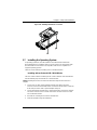
3-2 Installing Blade Modules..................................................................3-1
Powering Up a Blade Unit.......................................................................3-1
Powering Down a Blade Unit ..................................................................3-1
Removing a Blade Unit from the Enclosure............................................3-2
Removing/Replacing the Blade Cover....................................................3-2
Installing a Blade Unit into the Enclosure ...............................................3-2
3-3 Processor Installation .......................................................................3-4

SBI-7427R-S3 Blade Module User’s Manual
vi
3-4 Onboard Battery Installation............................................................3-9
3-5 Memory Installation...........................................................................3-9
Populating Memory Slots........................................................................3-9
DIMM Installation..................................................................................3-11
3-6 Hard Disk Drive Installation...........................................................3-12
3-7 Installing the Operating System....................................................3-13
Installing with an External USB CD-ROM Drive....................................3-13
Installing via PXE Boot..........................................................................3-14
Installing via Virtual Media (Drive Redirection) .....................................3-14
3-8 Management Software...................................................................3-14
3-9 Configuring and Setting up RAID.................................................3-14
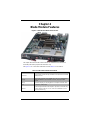
Chapter 4 Blade Module Features..............................................4-1
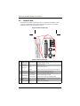
4-1 Control Panel.....................................................................................4-2
Power Button ..........................................................................................4-3
KVM Button.............................................................................................4-3
LED Indicators ........................................................................................4-3
KVM Connector.......................................................................................4-3
4-2 Mainboard...........................................................................................4-4
Jumpers..................................................................................................4-6
CMOS Clear............................................................................................4-6
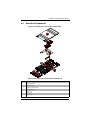
4-3 Blade Unit Components...................................................................4-7
Memory Support .....................................................................................4-8
Hard Disk Drives.....................................................................................4-8
Chapter 5 BIOS.......................................................................................5-1
5-1 Introduction.........................................................................................5-1
System BIOS ..........................................................................................5-1
How To Change the Configuration Data .................................................5-1
Starting the Setup Utility..........................................................................5-1
5-2 BIOS Updates....................................................................................5-2
Flashing BIOS.........................................................................................5-2
5-3 Running Setup...................................................................................5-3
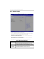
5-4 Main BIOS Setup...............................................................................5-4
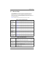
5-5 Advanced Setup................................................................................5-5
5-6 Event Logs Setup............................................................................5-14
5-7 IPMI Setup........................................................................................5-15
5-8 Boot...................................................................................................5-16

vii
Table of Contents
5-9 Security.............................................................................................5-16
5-10 Save & Exit.....................................................................................5-17
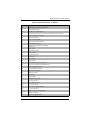
Appendix A BIOS POST Codes....................................................A-1
A-1 BIOS POST Messages....................................................................A-1
A-2 BIOS POST Codes...........................................................................A-3
Recoverable POST Errors......................................................................A-4
Terminal POST Errors.............................................................................A-4

SBI-7427R-S3 Blade Module User’s Manual
viii
Notes

1-1
Chapter 1
Introduction
1-1 Overview
This user’s manual covers the SBI-7427R-S3 blade module. This blade module is a
compact self-contained server that connects into a pre-cabled enclosure that provides
power, cooling, management and networking functions. One enclosure for the
SBI-7427R-S3 blade module can hold fourteen blade units.
In this manual, “blade system” refers to the entire system (including the enclosure and
blades units), “blade” or “blade unit” refers to a single blade module and “blade
enclosure” is the chassis that the blades, power supplies and modules are housed
within.
Please refer to our web site for information on operating systems that have been
certified for use with the SuperBlade (www.supermicro.com/products/superblade/).
1-2 Product Checklist of Typical Components
Your blade module ships with its B9DR7 mainboard already installed in its chassis.
Memory, hard disk drives and the CPU must all be installed by the user after shipment.
See Chapter 3: "Setup and Installation" on page 3-1 for details on installation of these
components.
Aside from the blade module unit itself, the following optional Mezzanine add-on cards
(with 10GbE or Infiniband Switch) may be ordered for your blade module:
• AOC-XEH-iN2
• AOC-IBH-XDD
• AOC-IBH-XQD
• AOC-IBH-XQS
• AOC-IBH-XDS
See the Supermicro website and the SuperBlade Network Modules User’s Manual on
your SuperBlade system’s CD-ROM for more details on these add-on cards.

SBI-7427R-S3 Blade Module User’s Manual
1-2
1-3 Blade Module Features
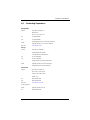
Table 1-1 lists the main features of the SBI-7427R-S3 blade module. See the
proceeding section for components typically included in a blade system and other
optional components. Specific details for the SBI-7427R-S3 blade module are found in
Chapter 4: "Blade Module Features" on page 4-1.
Processors
The SBI-7427R-S3 blade module supports dual 2011-pin (LGA 2011 Socket R) Intel
Xeon E5-2600 series processors.
Refer to the Supermicro web site for a complete listing of supported processors (http://
www.supermicro.com/products/superblade). Please note that you will need to check the
detailed specifications of a particular blade module for a list of the CPUs it supports.
Details on installation of the processor into the SBI-7427R-S3 blade module are found in
Chapter 3: "Setup and Installation" on page 3-1.
Memory
Both the SBI-7427R-S3 blade module have sixteen (16) 240-pin DIMM sockets that can
support up to 256 GB RDIMM or 64 GB UDIMM of Very Low Profile (VLP) DDR3 1600/
1333/1066 MHz speed SDRAM. Memory is interleaved, which requires modules of the
same size and speed to be installed in groups (of two or three).
Please refer to the Supermicro web site for a list of supported memory
(www.supermicro.com/products/superblade). The detailed specifications for a blade
module will contain a link to a list of recommended memory sizes and manufacturers.
Details on installation of memory modules into the SBI-7427R-S3 blade module are
found in Chapter 3: "Setup and Installation" on page 3-1.
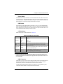
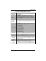
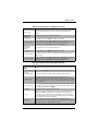
Table 1-1. SBI-7427R-S3 Blade Module Specification Features
Mainboard
B9DR7 (proprietary form factor)
Chassis Dimensions (HxWxD): 11.32” x 1.19” x 18.9”
Processors
Dual or quad core Intel
™
Xeon
®
E5-2600 series 2011-pin processors.
Please refer to our web site for a complete listing of supported processors.
FSB Speed QPI up to 8 GT/s
Chipset Intel C602J
Graphics Controller Integrated Matrox G200 Graphics
BIOS 16 MB SPI Flash EEPROM with AMI® BIOS
Memory Capacity
Supports up to 256 GB of RDIMM and 64 GB of UDIMM VLP DDR3 1600/
1333/1066 MHz speed SDRAM in sixteen (16) 240-pin DIMM sockets
HDD Controller Intel C602J on-chip controller for three Serial ATA drives
Hard Drive Bays Includes three hot-swap drive bays for 2.5" SAS/SATA/SSD disk drives

1-3
Chapter 1: Introduction
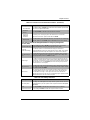
Storage
The SBI-7427R-S3 blade module can have three 2.5" SATA (Serial ATA)/SSD hard disk
drives in front-mounted easy removable carriers. See Chapter 3: "Setup and
Installation" on page 3-1 for storage installation details.
RAID
Each SBI-7427R-S3 blade module supports up to three hard drives, which may be used
to create a RAID 0, 1, 5 and 10 (Windows) or RAID 0, 1 and 10 (Linux) array. For RAID
setup use the procedure below. This blade’s BIOS has a RAID utility available in its
setup.
With two or hard drives per blade, the following RAID configurations are supported:
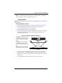
• RAID 0 (Data Striping): this writes data in parallel, interleaved (“striped”) sections on
two hard drives. Data transfer rate is doubled over using a single disk.
• RAID1 (Data Mirroring): an identical data image from one drive is copied to another
drive. The second drive must be the same size or larger than the first drive.
• Enhanced RAID 5 or RAID 10 (Data Mirroring): as RAID1 with data mirrored from
one or more disks to one or more disks of a second, larger size. You can couple the
disks from the source to create a virtual volume and use one or more disks of a
second, larger size to provide a single larger volume (or multiple larger volumes)
that serve as the mirroring drive or drives for the array.
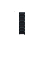
Density
A maximum of fourteen blade modules may be installed into a single blade enclosure.
Each blade enclosure is a 7U form factor, so a standard 42U rack may accommodate up
to six enclosures with 84 blade modules, or the equivalent of 84 1U servers. With the
inclusion of six CMM modules, twelve Gigabit Ethernet switches and six InfiniBand
switches, this would occupy up to 108U space in a conventional 1U server configuration.
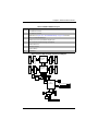
Figure 1-1 displays a view of a full rack with six blade enclosures in it, each with
fourteen blades to an enclosure.

SBI-7427R-S3 Blade Module User’s Manual
1-4
Figure 1-1. Full Rack of Blade Enclosures and Blade Servers

1-5
Chapter 1: Introduction
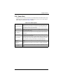
1-4 Contacting Supermicro
Headquarters
Address: Super Micro Computer, Inc.
980 Rock Ave.
San Jose, CA 95131 U.S.A.
Tel: +1 (408) 503-8000
Fax: +1 (408) 503-8008
Email:
[email protected] (General Information)
[email protected] (Technical Support)
Web Site: www.supermicro.com
Europe
Address: Super Micro Computer B.V.
Het Sterrenbeeld 28, 5215 ML
‘s-Hertogenbosch, The Netherlands
Tel: +31 (0) 73-6400390
Fax: +31 (0) 73-6416525
Email:
[email protected] (General Information)
[email protected] (Technical Support)
[email protected] (Customer Support)
Asia-Pacific
Address: Super Micro Computer, Inc.
4F, No. 232-1, Liancheng Rd.
Chung-Ho 235, Taipei County
Taiwan, R.O.C.
Tel: +886-(2) 8226-3990
Fax: +886-(2) 8226-3991
Web Site: www.supermicro.com.tw
Technical Support:
Email: [email protected]
Tel: +886-(2) 8226-5990

SBI-7427R-S3 Blade Module User’s Manual
1-6
Notes

2-1
Chapter 2
Standardized Warning Statements
2-1 About Standardized Warning Statements
The following statements are industry standard warnings, provided to warn the user of
situations which have the potential for bodily injury. Should you have questions or
experience difficulty, Contact Supermicro's Technical Support department for
assistance. Only certified technicians should attempt to install or configure components.
Read this appendix in its entirety before installing or configuring components in the
Supermicro chassis.
These warnings may also be found on our web site at http://
www.supermicro.com/about/policies/safety_information.cfm.
Warning Definition
Warning!
This warning symbol means danger. You are in a situation that could cause
bodily injury. Before you work on any equipment, be aware of the hazards
involved with electrical circuitry and be familiar with standard practices for preventing
accidents.
此警告符号代表危险。
您正处于可能受到严重伤害的工作环境中。在您使用设备开始工作之前,必须充分意识
到触电的危险,并熟练掌握防止事故发生的标准工作程序。请根据每项警告结尾的声明
号码找到此设备的安全性警告说明的翻译文本。

SBI-7427R-S3 Blade Module User’s Manual
2-2
Warnung
WICHTIGE SICHERHEITSHINWEISE
Dieses Warnsymbol bedeutet Gefahr. Sie befinden sich in einer Situation, die zu
Verletzungen führen kann. Machen Sie sich vor der Arbeit mit Geräten mit den
Gefahren elektrischer Schaltungen und den üblichen Verfahren zur Vorbeugung vor
Unfällen vertraut. Suchen Sie mit der am Ende jeder Warnung angegebenen
Anweisungsnummer nach der jeweiligen Übersetzung in den übersetzten
Sicherheitshinweisen, die zusammen mit diesem Gerät ausgeliefert wurden.
BEWAHREN SIE DIESE HINWEISE GUT AUF.
INSTRUCCIONES IMPORTANTES DE SEGURIDAD
Este símbolo de aviso indica peligro. Existe riesgo para su integridad física. Antes de
manipular cualquier equipo, considere los riesgos de la corriente eléctrica y
familiarícese con los procedimientos estándar de prevención de accidentes. Al final de
cada advertencia encontrará el número que le ayudará a encontrar el texto traducido en
el apartado de traducciones que acompaña a este dispositivo.
GUARDE ESTAS INSTRUCCIONES
IMPORTANTES INFORMATIONS DE SÉCURITÉ
Ce symbole d'avertissement indique un danger. Vous vous trouvez dans une situation
pouvant entraîner des blessures ou des dommages corporels. Avant de travailler sur un
équipement, soyez conscient des dangers liés aux circuits électriques et
familiarisez-vous avec les procédures couramment utilisées pour éviter les accidents.
Pour prendre connaissance des traductions des avertissements figurant dans les
consignes de sécurité traduites qui accompagnent cet appareil, référez-vous au numéro
de l'instruction situé à la fin de chaque avertissement.
CONSERVEZ CES INFORMATIONS.
ןןונקת תורהצהאהרהז
ןה תואבה תורהצהא ינפמ שמתשמה תא ריהזהל תנמ לע ,היישעתה ינקת יפ לע תורהז הלבח
ה וא תולאש שיו הדימב .תירשפא תיזיפי ,יהשלכ היעבב תולקתרוציל שי הכימת תקלחמ םע רשק
רידגהל וא ןיקתהל םיאשר דבלב םיכמסומ םיאנכט .ורקימרפוס לש תינכט תאה .םיביכר
אורקל שי .ורקימרפוס יזראמב םיביכרה תרדגה וא תנקתה ינפל ואולמב חפסנה תא

2-3
Chapter 2: Standardized Warning Statements
BELANGRIJKE VEILIGHEIDSINSTRUCTIES
Dit waarschuwings symbool betekent gevaar. U verkeert in een situatie die lichamelijk
letsel kan veroorzaken. Voordat u aan enige apparatuur gaat werken, dient u zich
bewust te zijn van de bij een elektrische installatie betrokken risico's en dient u op de
hoogte te zijn van de standaard procedures om ongelukken te voorkomen. Gebruik de
nummers aan het eind van elke waarschuwing om deze te herleiden naar de
desbetreffende locatie.
BEWAAR DEZE INSTRUCTIES
. ﻲﻓ ﻚﻧﺍ ﻥﺃ ﻦﻜﻤﻳ ﺔﻟﺎﺣ ﻲﻓ ﺐﺒﺴﺘﺗ ﺔﺑﺎﺻﺍ ﺔﻳﺪﺴﺟ ﺰﻣﺮﻟﺍ ﺍﺬﻫ ﻲﻨﻌﻳ ﺮﻄﺧ !ﺮﻳﺬﺤﺗ
ﻥﺃ ﻞﺒﻗ ﻱﺃ ﻰﻠﻋ ﻞﻤﻌﺗ ﺕﺍﺪﻌﻣ،ﻛﻢﻠﻋ ﻰﻠﻋ ﻦ ﻦﻋ ﺔﻤﺟﺎﻨﻟﺍ ﺮﻁﺎﺨﻤﻟﺎﺑ ﺮﺋﺍﻭﺪﻟﺍ
ﺔﻴﺋﺎﺑﺮﻬﻜﻟﺍ
ﻛﻭﺔﻳﺍﺭﺩ ﻰﻠﻋ ﻦ ﺭﺎﻤﻤﻟﺎﺑﺕﺎﺳ ﺔﻴﺋﺎﻗﻮﻟﺍ ﻟ ﻊﻨﻤﻉﻮﻗﻭ ﻱﺃﺙﺩﺍﻮﺣ
ﻢﻗﺭ ﻡﺪﺨﺘﺳﺍ ﻥﺎﻴﺒﻟﺍ ﺹﻮﺼﻨﻤﻟﺍ ﺔﻳﺎﻬﻧ ﻲﻓ ﺮﻳﺬﺤﺗ ﻞﻛ ﺭﻮﺜﻌﻠﻟ ﺎﻬﺘﻤﺟﺮﺗ

SBI-7427R-S3 Blade Module User’s Manual
2-4
Installation Instructions
Warning!
Read the installation instructions before connecting the system to the power
source.
Warnung
Vor dem Anschließen des Systems an die Stromquelle die Installationsanweisungen
lesen.
¡Advertencia!
Lea las instrucciones de instalación antes de conectar el sistema a la red de
alimentación.
Attention
Avant de brancher le système sur la source d'alimentation, consulter les directives
d'installation.
Waarschuwing
Raadpleeg de installatie-instructies voordat u het systeem op de voedingsbron aansluit.
אורקל שי רוקמל תכרעמה רוביח ינפל הנקתה תוארוה תאחתמ.
ﻟﺍ ﺕﺍﺩﺎﺷﺭﺇ ﺮﻗﺍﺐﻴﻛﺮﺘ ﻞﻴﺻﻮﺗ ﻞﺒﻗ ﻰﻟﺇ ﻡﺎﻈﻨﻟﺍ ﺔﻗﺎﻄﻠﻟ ﺭﺪﺼﻣ

2-5
Chapter 2: Standardized Warning Statements
Circuit Breaker
Warning!
This product relies on the building's installation for short-circuit (overcurrent)
protection. Ensure that the protective device is rated not greater than: 250 V,
20 A.
Warnung
Dieses Produkt ist darauf angewiesen, dass im Gebäude ein Kurzschluss- bzw.
Überstromschutz installiert ist. Stellen Sie sicher, dass der Nennwert der
Schutzvorrichtung nicht mehr als: 250 V, 20 A beträgt.
¡Advertencia!
Este equipo utiliza el sistema de protección contra cortocircuitos (o sobrecorrientes) del
edificio. Asegúrese de que el dispositivo de protección no sea superior a: 250 V, 20 A.
Attention
Pour ce qui est de la protection contre les courts-circuits (surtension), ce produit dépend
de l'installation électrique du local. Vérifiez que le courant nominal du dispositif de
protection n'est pas supérieur à :250 V, 20 A
לע ךמתסמ הז רצומנגהה תעינמל םינבמב תנקתומה יכ אדוול שי .ילמשח רצק
רצקה ינפמ ןגמה רישכמה ילמשחהמ רתוי אל אוה-250 V, 20 A
ﺞﺘﻨﻤﻟﺍ ﺍﺬﻫ ﻰﻠﻋ ﺪﻤﺘﻌﻳ ﺕﺍﺪﻌﻣ ﺔﻳﺎﻤﺤﻟﺍ ﺓﺮﻴﺼﻘﻟﺍﺮﺋﺍﻭﺪﻟﺍ ﻦﻣ ﺎﻬﺘﻴﺒﺜﺗ ﻢﺗ ﻲﺘﻟﺍ ﻲﻓ
ﻰﻨﺒﻤﻟﺍ
20A, 250V : ﻦﻣ ﺪﻛﺄﺗ ﻥﺃ ﻢﻴﻴﻘﺗ ﺯﺎﻬﺠﻟﺍ ﻟﺍﻲﺋﺎﻗﻮ ﺲﻴﻟ ﻦﻣ ﺮﺜﻛﺃ

SBI-7427R-S3 Blade Module User’s Manual
2-6
Waarschuwing
Dit product is afhankelijk van de kortsluitbeveiliging (overspanning) van uw electrische
installatie. Controleer of het beveiligde aparaat niet groter gedimensioneerd is dan
220V,20A.
Power Disconnection Warning
Warning!
The system must be disconnected from all sources of power and the power
cord removed from the power supply module(s) before accessing the chassis
interior to install or remove system components.
在你打开机箱并安装或移除内部器件前 , 必须将系统完全断电 , 并移除电源线 .
Warnung
Das System muss von allen Quellen der Energie und vom Netzanschlusskabel getrennt
sein, das von den Spg.Versorgungsteilmodulen entfernt wird, bevor es auf den
Chassisinnenraum zurückgreift, um Systemsbestandteile anzubringen oder zu
entfernen.
¡Advertencia!
El sistema debe ser disconnected de todas las fuentes de energía y del cable eléctrico
quitado de los módulos de fuente de alimentación antes de tener acceso el interior del
chasis para instalar o para quitar componentes de sistema.
Page is loading ...
Page is loading ...
Page is loading ...
Page is loading ...
Page is loading ...
Page is loading ...
Page is loading ...
Page is loading ...
Page is loading ...
Page is loading ...
Page is loading ...
Page is loading ...
Page is loading ...
Page is loading ...
Page is loading ...
Page is loading ...
Page is loading ...
Page is loading ...
Page is loading ...
Page is loading ...
Page is loading ...
Page is loading ...
Page is loading ...
Page is loading ...
Page is loading ...
Page is loading ...
Page is loading ...
Page is loading ...
Page is loading ...
Page is loading ...
Page is loading ...
Page is loading ...
Page is loading ...
Page is loading ...
Page is loading ...
Page is loading ...
Page is loading ...
Page is loading ...
Page is loading ...
Page is loading ...
Page is loading ...
Page is loading ...
Page is loading ...
Page is loading ...
Page is loading ...
Page is loading ...
Page is loading ...
Page is loading ...
Page is loading ...
Page is loading ...
Page is loading ...
Page is loading ...
Page is loading ...
Page is loading ...
Page is loading ...
Page is loading ...
Page is loading ...
Page is loading ...
Page is loading ...
Page is loading ...
Page is loading ...
Page is loading ...
Page is loading ...
Page is loading ...
Page is loading ...
Page is loading ...
-
 1
1
-
 2
2
-
 3
3
-
 4
4
-
 5
5
-
 6
6
-
 7
7
-
 8
8
-
 9
9
-
 10
10
-
 11
11
-
 12
12
-
 13
13
-
 14
14
-
 15
15
-
 16
16
-
 17
17
-
 18
18
-
 19
19
-
 20
20
-
 21
21
-
 22
22
-
 23
23
-
 24
24
-
 25
25
-
 26
26
-
 27
27
-
 28
28
-
 29
29
-
 30
30
-
 31
31
-
 32
32
-
 33
33
-
 34
34
-
 35
35
-
 36
36
-
 37
37
-
 38
38
-
 39
39
-
 40
40
-
 41
41
-
 42
42
-
 43
43
-
 44
44
-
 45
45
-
 46
46
-
 47
47
-
 48
48
-
 49
49
-
 50
50
-
 51
51
-
 52
52
-
 53
53
-
 54
54
-
 55
55
-
 56
56
-
 57
57
-
 58
58
-
 59
59
-
 60
60
-
 61
61
-
 62
62
-
 63
63
-
 64
64
-
 65
65
-
 66
66
-
 67
67
-
 68
68
-
 69
69
-
 70
70
-
 71
71
-
 72
72
-
 73
73
-
 74
74
-
 75
75
-
 76
76
-
 77
77
-
 78
78
-
 79
79
-
 80
80
-
 81
81
-
 82
82
-
 83
83
-
 84
84
-
 85
85
-
 86
86


Supermicro Processor Blade SBI-7427R-S3 User manual
- Category
- Server barebones
- Type
- User manual
Ask a question and I''ll find the answer in the document
Finding information in a document is now easier with AI
Related papers
-
Supermicro SBI-7427R-SH User manual
-
-
SUPER MICRO Computer SBI-7426T-S3 User manual
-
-
SUPER MICRO Computer Processor Blade SBI-7127R-S6 User manual
-
-
-
-
-