IKEA IDT870SAGX0 Installation guide

Category
Dishwashers
Type
Installation guide
INSTALLATION INSTRUCTIONS
UNDERCOUNTER DISHWASHER
STAINLESS STEEL TUB
LAVAVAJILLAS EMPOTRADA CON TINA
DE ACERO INOXIDABLE
INSTRUCTIONS D’INSTALLATION
LAVE-VAISSELLE ENCASTRÉ
AVEC CUVE EN ACIER INOXYDABLE
Table of Contents ........................................................2
Indice
........................................................................27
Table des matières
....................................................52
W10806906H
2
TABLE OF CONTENTS
DISHWASHER SAFETY ................................................... 3
INSTALLATION REQUIREMENTS ................................... 4
Tools and Parts .........................................................................4
Location Requirements ............................................................. 6
Product and Cabinet Opening Dimensions ..............................7
Drain Requirements ..................................................................8
Water Supply Requirements .....................................................8
Electrical Requirements ............................................................8
INSTALLATION INSTRUCTIONS ..................................... 9
Prepare Cabinet Opening – NewUtilities .................................9
Install Optional Moisture Barrier ...............................................9
Electrical Connection .............................................................. 10
Prepare Dishwasher ................................................................11
Remove Access Panel ............................................................11
Connect Water Line to Fill Valve .............................................12
Connect Fill Hose to Fill Valve ................................................13
Drain Hose Connection ..........................................................13
Power Cord Connection .........................................................14
Install Door Handle .................................................................16
Place Diswasher in Cabinet ....................................................16
Custom Panel Installation .......................................................17
Choose Anchor Attachment Method ......................................17
Final Installation Check ...........................................................18
Secure Dishwasher inCabinetOpening .................................19
Direct Wire Connection ...........................................................20
Connect Water Line to House Shutoff Valve...........................22
Connect Drain Hose ..............................................................22
Complete Installation ..............................................................24
Install Access Panel ................................................................ 25
Check Operation .....................................................................26
If Dishwasher Does Not Operate ............................................26
Additional Tips ........................................................................26
3
DISHWASHER SAFETY
You Need to:
Slowly open dishwasher door while someone grasps the rear
of the dishwasher. Remove shipping materials and drainhose.
Close dishwasher door until latched.
NOTE: Each dishwasher is tested at the factory and may
contain some residual water in the tub as a result of the test.
Observe all governing codes and ordinances.
Install this dishwasher as specied in these instructions.
Installation should be performed by a qualied
servicetechnician.
The dishwasher must be installed to meet all electrical
andplumbing national and local codes and ordinances.
Care shall be exercised when the appliance is installed
orremoved, to reduce the likelihood of damage to the
powercord.
WARNING: To reduce the risk of electric shock, re, or injury
to persons, the installer must ensure that the dishwasher is
completely enclosed at the time of installation.
WARNING
Tip Over Hazard
Do not use dishwasher until completely installed.
Do not push down on open door.
Doing so can result in serious injury or cuts.
4
INSTALLATION REQUIREMENTS
TOOLS AND PARTS
Gather the recommended tools and parts before starting
installation. Read and follow the instructions provided with
anytools listed here.
All Installations
Tools Needed:
Pliers Flat-blade screwdriver
Phillips screwdriver Utility knife
5
/
16
" (8 mm) and
1
/
4
" (6.35 mm)
nut drivers or hex sockets
Small level
Measuring tape or ruler
5
/
8
" (16 mm) open-end wrench
10" (254 mm) adjustable
wrench that opens to
1
1
/8" (29 mm)
Torx
®†
T20
®
and, if installing
custom front panels, Torx
®
T15
®
screwdrivers
Other Useful Items You May Need:
Flashlight Shallow pan
Bath towel Masking or duct tape
Parts Supplied:
Drain hose clamps (2)
(1 large/red and 1 small/green)
Drain hose
#10 x
1
/
2
" (12.7 mm)
Phillips-head screws (2)
Undercounter mounting
brackets (2)
Make sure all these parts are included in the literature package.
If parts are not included, call us at our toll-free number or visit
our website listed in the User Guide.
Door handle (on some models)
®
TORX, T15, and T20 are registred trademarks of Acument Intellectual Properties, LLC.
5
Other Parts Needed (not provided):
3
/
8
" (9.5 mm) Compression x
3
/
4
" (19 mm) Hose Fitting with
rubber seal and 90° elbow
(required to properly connect
household water line to the
dishwasher) (Whirlpool Part
Number W10685193)
Household Wiring (Metallic)
Strain Relief to fit
7
/8" (22mm)
hole (required to properly
secure household wiring to the
dishwasher terminal box)
(Whirlpool Part
Number 4396672)
NOTE: Use only UL Listed/
CSA Approved part.
Twist-On Wire Connectors
NOTES:
Conrm proper size for
connecting your gauge of
household wiring to the
16-gauge wiring in the
dishwasher.
Use only UL Listed/CSA
Approved parts.
Call us at our toll-free number, visit our website listed in the User
Guide for part numbers above, orsee local electrical/plumbing
supply retailer for equivalent.
Optional Accessory Parts Available:
Moisture Barrier Tape
NOTE: Moisture barrier tape
is an optional, added level
of protection if installing a
dishwasher under a wooden
countertop. (Whirlpool Part
Number 4396277)
Side Panel Kit
For enclosing the side of the
dishwasher when installing it
at the end of your cabinetry
(Whirlpool Part Number varies
with color.)
Call us at our toll-free number or visit our website listed in the
User Guide for part numbers above.
First-Time Installations
Check local codes. Check existing electrical supply. See the
“Electrical Requirements” section. It is recommended that
electrical connections be made by a licensed electrical installer.
Additional Tools Needed:
Small tubing cutter Wire stripper
Cordless drill with
1
/2" (12.7 mm),
3
/4" (19 mm) , and 1
1
/2" (38 mm)
hole saw bits
Additional Parts Needed (not provided):
Copper Tubing (
3
/8" (9.5 mm)
O.D. suggested) or Flexible
Braided WaterSupply Line Kit
(Whirlpool Part Number
W10278635RP). Kitincludes
braided hose and
3
/8" (9.5 mm)
compression x
3
/4" (19 mm)
hosefitting.
Screw-Type Clamps
1
1
/2
"-2" (38-50 mm)
(3maximum)
Optional-Longer Drain Hose
Maximum length 12 ft (3.7 m)
(Whirlpool Part Number 3385556
)
NOTE: Must meet AHAM/IAPMO
test standards, fit 1" (25mm)
drain connection, and be
resistant to heat and detergent
Call us at our toll-free number, visit our website listed in the
User Guide for part numbers above, orsee local plumbing
supply retailer for equivalent.
NOTE: If using a exible braided hose, replace inlet hose
after 5years to reduce the risk of hose failure. Record
hoseinstallation or replacement dates on the hose for
futurereference.
6
For Direct Wire For Power Cord
Cabinet G
rommet
For 1
1
/
2
" (38 mm) hole in
cabinet. (Whirlpool
PartNumber302797)
NOTE: Required for metal
cabine
ts
Power Cord Ki
t
Kit typically includes
power cord, metallic strain
relief,grommet, and twist-on
wi
re connectors. (Whirlpool
Part Number 4317824)
Call us at our toll-free number, visit our website listed in the User
Guide for part numbers above, orsee local electrical supply
retailer for equivalent.
LOCATION REQUIREMENTS
Dishwasher must be fully enclosed (top, sides, back, and oor)
upon installation. A side panel kit is available from your dealer
forinstalling your dishwasher at the end of your cabinetry.
An optional moisture barrier accessory is also available for
installing underneath a wooden countertop. See the “Tools
and Parts” section at the front of the guide for part details
andorders.
Check location where dishwasher will be installed. The location
must provide:
Convenient access for loading and unloading dishes. Corner
locations require a 2" (51 mm) minimum clearance between
the side of the dishwasher door and the wall or cabinet.
Easy access to water, electricity, and drain:
Grounded electrical supply is required.
This dishwasher has a water heating feature and also
requires a connection to a hot water supply line.
Make sure pipes, wires and drain hose are within the
shaded area shown in the “Product and Cabinet Opening
Dimensions” section.
Do not run drain lines, water lines, or electrical wiring where
they can interfere with or contact dishwasher motor or legs.
Shelter dishwasher and water lines leading to dishwasher
against freezing. Damage from freezing is not covered by
the warranty.
NOTE: If dishwasher will be left unused for a period of time
or in a location where it may be subject to freezing, have it
winterized by authorized service personnel.
If installed in new construction, ush the water supply line
of debris before connecting it to the ll valve. If it is not
ushed, debris from the water supply could plug the ll
valve screen.
A square opening for proper operation and appearance
The cabinet front to be perpendicular to oor
A level oor
Helpful Hint: If oor at front of opening is not level with oor
at rear of opening, shims may be used to level dishwasher.
NOTE: To avoid shifting during dishwasher operation, shims
must be securely attached to the oor.
The location where the dishwasher will be installed must
provide clearance between motor and ooring. Motor should
not touch the oor.
Do not install dishwasher over carpeted ooring.
7
Product and Cabinet Opening Dimensions
23
7
/8"
(606 mm)
30"
(762 mm)
"
3
7
/
16
7
/16"
(87 mm - 113 mm)
33
1
/2"
(851 mm)
min. with
wheels
removed
24
1
/2"
(622 mm)
B
3
/4"
(19 mm)
A
30"
(762 mm)
3
3
/4"
(95 mm)
21"
(533 mm)
C
24"
(610 mm)
E
24"
(610 mm)
34"
(864 mm)
D
3
"
(76 mm)
1
3
/4"
(44 mm)
6
3
/4"
(172 mm)
2
1
/4"
(64 mm)
2
1
/4"
(57 mm)
2
"
(51 mm)
6
1
/4"
(159 mm)
10
1
/2"
(267 mm)
4
"
(102 mm)
A. Insulation may be compressed (not used on all models).
B. For panel-ready models, dishwasher depth is 24" (610 mm),
not including the
3
/
4
" (19 mm) custom door panel.
C. Door handles may protrude forward of the face of the
dishwasher, varies by model.
For 4 (113 mm) toe kick, height of cabinet opening is
34
7
/
16
1
/
2
" (876 mm).
Check that all surfaces have no protrusions
that would prohibit dishwasher installation.
D. Measured from the lowest point on the underside
of the countertop. May be reduced to 33
1
/
2
"
area of insulation (blanket) on dishwasher.
E. Minimum, measured from narrowest point
of opening
NOTE: Shaded areas
of cabinet walls
show where utility
connections may
be installed.
8
ELECTRICAL REQUIREMENTS
Be sure that the electrical connection and wire size are
adequateand in conformance with the National Electrical
Code, ANSI/NFPA 70 - latest edition, and all local codes
andordinances.
A copy of the above code standards can be obtained from:
National Fire Protection Association
1 Batterymarch Park
Quincy, MA 02169-7471
You Must Have:
120 V, 60 Hz, AC-only, 15- or 20 A, fused
electrical supply
Copper wire only
A maximum of 2 field wiring supply conductors
(12AWGlargest size) plus 1 grounding conductor
arepermitted in the terminal box.
We Recommend:
A time-delay fuse or circuit breaker
A separate circuit
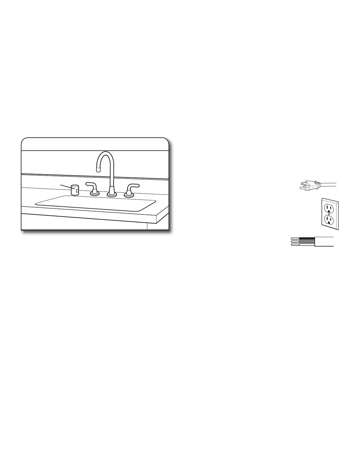
If Connecting Dishwasher with a Power Cord:
Use UL Listed power cord kit marked for
use with dishwasher. See the “Tools and
Parts” section at the front of the guide for
part details and orders.
Plug into a grounded 3prong outlet. Outlet must
meet all localcodes and ordinances.
If Connecting Dishwasher with Direct Wiring:
Use exible, armored, or nonmetallic
sheathed copper wire with grounding
wire that meets the wiring requirements
for your home and local codes and ordinances.
Use a UL Listed/CSA Approved metallic strain relief.
Seethe“Tools and Parts” section at the front of the
guideforpart details and orders.
DRAIN REQUIREMENTS
A new drain hose is supplied with your dishwasher.
Ifdrainhose is not long enough, use a new drain hose witha
maximum length of 12 ft (3.7 m) that meets all currentAHAM/
IAPMO test standards, is resistant to heat and detergent, and
ts the 1" (25 mm) drain connector of thedishwasher. See
the “Tools and Parts” section at the front ofthe guide for part
details and orders.
NOTE: Do not connect multiple drain hoses together.
Make sure to connect drain hose to waste tee or disposer
inlet above drain trap in house plumbing and 20" (508 mm)
minimum above the oor. It is recommended that the drain
hose either be looped up and securely fastened to the
underside of the counter or be connected to an air gap.
Make sure to use an air gap if the drain hose is connected
tohouse plumbing lower than 20" (508 mm) above
suboororoor.
If required, the air gap should be installed in accordance
withthe air gap installation instructions. When you are
connecting the air gap, a rubber hose (not provided) will
beneeded to connect to the waste tee or disposer inlet.
Use
1
/2" (12.7 mm) minimum I.D. drain line fittings.
WATER SUPPLY REQUIREMENTS
This dishwasher has a water heating feature and also
requires a connection to a hot water supply line.
A hot water line with 20 to 120 psi (0.
138 to
0.827 mPa)
waterpressure can be verified by a licensed plumber.
120°F (49°C) water at dishwasher
3
/
8
"
(9.5 mm)
O.D. copper tubing with compression fitting or
flexible
braided water supply line. See the “Tools and Parts”
section atthe front of the guide for part details and orders.
NOTE:
1
/2" (12.7 mm) minimum plastic tubing is not
recommended.
A 90° elbow with
3
/4" (19 mm) hose connection with rubber
washer. See the “Tools and Parts” section at the front of the
guide forpart details and orders.
Do not solder within 6" (152 mm) of the water inlet valve.
If installed in new construction, make sure the house
watersupply lines have been flushed prior to connecting
thedishwasher to remove any debris that may exist in
thesupply line.
NOTE: If replacing an existing dishwasher, it is recommended
to install a new water line (see the “Tools and Parts” section at
the front of the guide for part details) and drain hose (supplied)
with the new dishwasher.
Use of air gap
Air gap
9
PREPARE CABINET OPENING –
NEW UTILITIES
NOTE: Refer to the “Product and Cabinet Opening
Dimensions” section for the correct hole placement and
dimensions of the shaded area.
Drill a 1
1
/
2
" (38 mm) drain hose hole in the side or rear of
cabinet, depending on location of drain hose routing and
drain hose connection location.
Drill a
1
/
2
" (12.7 mm) water supply hose hole in the side or
rear of cabinet, depending on location of water supply
routing and connection location
Drill a 1
1
/
2
" (38 mm) electrical conduit hole in the right-hand
side or rear of cabinet.
WARNING
Disconnect electrical power at the fuse box or circuit
breaker box before installing dishwasher.
Failure to do so can result in death or electrical shock.
Electrical Shock Hazard
1. Disconnect power
Disconnect electrical power at the fuse box or circuit
breaker box before installing dishwasher.
2. Shut off water supply
Shut off the water supply to the dishwasher.
3. Drill hole locations -
new construction
Preferred
location
Optional
location
1
1
/
2
"
(38mm)
1
/
2
"
(12.7mm)
Wood cabinet: Sand the hole until smooth.
Metal cabinet: Cover edges of hole with grommet included
withpower cord kit. See the “Tools and Parts” section at
thefront of the guide forpart details.
Helpful Tip: Wiring the dishwasher will be easier if you route
thecable into the cabinet opening from the right-hand side.
INSTALL OPTIONAL MOISTURE BARRIER –
RECOMMENDED FOR WOOD COUNTERTOPS
See the “Tools and Parts” section at the front of the guide for
part details and orders. Make sure the area under the cabinet
is clean and dry for installation of the moisture barrier. Remove
the backing of the moisture barrier, and apply to underside of
thecountertop along the front edge of the counter.
NOTE: Install wood shims if side anchoring and the gap
between the sides of the cabinet and sides of the dishwasher
are greater than
1
/
2
" (12.7 mm) on each side or are greater than
the length of the side anchor screws.
4. Sand holes smooth
Metal
cabinet
Wood
cabinet
Moisture barrier/wood shims
Moisture
barrier
Install
wood
shims
INSTALLATION INSTRUCTIONS
10
Built-up oors: If the kitchen oor is higher than the cabinet
opening’s oor - for example, the kitchen oor tile does not
extend into the cabinet opening - add shims, as needed, in the
area shown to bring the dishwasher up to 34" (864 mm) below
the countertop.
NOTE: Shims must be securely attached to oor to avoid
movement when the dishwasher is in use.
Remove and discard the foam blocks (if blocks are present;
notall models have them) located above the front legs on
eachside of the dishwasher. The blocks cover the rope/link
pulleys on the dishwasher.
5. Built-up oors –
addshimsasneeded
6. Remove foam block
Foam block
Cut insulation blanket along perforation for cabinet opening
height of 33
1
/
2
" (851 mm). For other cabinet opening heights,
donot cut the insulation blanket.
ELECTRICAL CONNECTION
– For Direct Wire, begin with Step 7
– For Power Cord, wait until Step 22
If installing with direct wire, route the cable as shown.
Route cable from power supply through cabinet hole. (Cable
must extend to the right front side of cabinet opening.) Tape
cable to the oor in area shown. This will prohibit cable from
moving when dishwasher is moved into cabinet opening.
NOTE: If removing a previous dishwasher with a power cord,
you will need to transfer the power cord to the new dishwasher.
If installing into a
33
1
/
2
" (851mm)opening
7. Direct wire – route cable
11
PREPARE DISHWASHER
Helpful Tip: Place cardboard under dishwasher until installed
incabinet opening to avoid damaging oor covering.
Using 2 or more people, grasp sides of dishwasher door
frame,and place the dishwasher on its back.
Do not use the door panel as a worktable without rst
coveringitwith a towel to avoid scratching the door panel.
NOTE: On some models, once the dishwasher is on its back,
pull on the door handle to remove it from the access panel.
WARNING
Tip Over Hazard
Do not use dishwasher until completely installed.
Do not push down on open door.
Doing so can result in serious injury or cuts.
WARNING
Excessive Weight Hazard
Use two or more people to move and install
dishwasher.
Failure to do so can result in back or other injury.
8. Put dishwasher on its back
REMOVE ACCESS PANEL
– For Plastic Access Panels, go to Step 9
– For Metal Access Panels, go to Step 10
Using a at-blade screwdriver, turn the plastic fasteners
1
/
4
turn counterclockwise to unlock them. Remove panel. Do
not remove tech sheet from access panel. Go to Step 11.
Using a
1
/
4" ( 6.35 mm) nut driver or Phillips screwdriver, remove
2 screws attaching access panel to dishwasher. Do not remove
tech sheet from access panel.
9. Plastic panel
1
/
4
turn
10. Metal panel
12
Measure height of cabinet opening from underside of
countertop to oor where dishwasher will be installed.
Be sure to measure the lowest point on the underside
of the countertop and the highest point on the oor.
Adjust both front leveling legs to the same height. Put the rear
wheels in the correct position according to the “Dishwasher
Height Adjustment Chart.”
NOTE: If the minimum cabinet opening height is less
than 34" (864 mm), the rear wheels can be removed for
additionalclearance.
This will allow the dishwasher to t into a 33
1
/
2
" (851 mm)
highcabinet opening, but the dishwasher will be more
difculttomove. Measurements are approximate.
11. Measure cabinet opening
Dishwasher Height Adjustment Chart
Cabinet opening
height
Front legs
height
Wheel
position
Insulation
blanket
33
1
/
2
" (851 mm)
3
/
8
" (9.8 mm) Removed Cut
34" (864 mm)
9
/
16
" (14 mm) 1 No Cut
34
1
/
4
" (871 mm)
13
/
16
" (21 mm) 2 No Cut
34
1
/
2
" (876 mm)
11
/
16
" (27 mm) 3 No Cut
Front legs – A
Refer to the “Dishwasher Height Adjustment Chart” for wheel
position and for height of front legs needed for your cabinet
opening height.
Remove and discard the plastic rail cover on each side of
thedishwasher frame. To remove the plastic rail cover, push
upward and back to unsnap it from the dishwasher frame.
CONNECT WATER LINE TO FILL VALVE
– For Copper line, begin with Step 14
– For Flexible line, begin with Step 16
If using copper tubing, measure overall length of copper
tubing required to reach the water supply, cut to length, and
attach with compression ttings.
12. Adjust wheels and legs
13. Remove plastic rail cover
(only on certain models)
Plastic
rail cover
14. Copper water line
13
Copper tubing only: Put the tubing into the 90° elbow tting
as far as it will go. (The copper tubing bends and kinks easily.)
Slide the nut and ferrule forward and start the nut onto the
elbowthreads.
NOTE: To avoid vibration during operation, route the water
supply line so that it does not touch the dishwasher base,
frame,or motor. Go to Step 17.
Flexible braided line: Conrm the exible braided line is long
enough. See the “Tools and Parts” section at the front of the
guide for part details and orders.
Get
3
/8" (9.5 mm) compression x
3
/4" (19 mm) hose fitting with
90° elbow. See the “Tools and Parts” section at the front of the
guide for part details and orders. Connect the
3
/8" (9.5 mm)
compression fitting of the 90° elbow fitting to the water supply
line. Attach such that the 3
/
4
" (19 mm) connection is facing
upward as shown above.
15. Slide nut and ferrule onto tubing
(copper tubing only)
Nut
Ferrule
16. Flexible line
17. Add 90° elbow tting to the
watersupply line
CONNECT FILL HOSE TO FILL VALVE
Be sure rubber washer is properly seated in fitting. Slide the
3
/
4
" (19 mm) fitting of the 90° elbow up to the valve and hand
tighten to avoid cross-threading. Hand tighten until the
coupling is tight. Using pliers, check the tightness of the
coupling. An additional
1
/
4
(6.35 mm) to
1
/
2
(12.7 mm) turn
may be required to seal the rubber gasket. Route fill hose out
the rear left side of unit.
NOTES:
Do not use Teon
®†
tape with compression ttings.
Do not over-tighten. Damage to the coupling can result.
DRAIN HOSE CONNECTION
Place towel under drain hose to catch any water in drain hose.
Place the small (green) drain hose clamp onto the small end
ofthe drain hose. Push the new drain hose into the rubber
drainhose connector up to the drain hose stop.
Using pliers, squeeze open the small drain hose clamp and
slide it onto the connector between stops.
®
TEFLON is a registered trademark of Chemours.
18. Tighten 90° elbow tting to valve
19. Connect drain hose
Stop
Stop
Drain hose stop
Drain hose
Rubber drain hose
connector
Small clamp
20. Slide clamp onto connector
Stop
Stop
Drain hose stop
Drain hose
Rubber drain hose
connector
Small clamp
14
NOTE: Route drain hose out the rear of the dishwasher.
POWER CORD CONNECTION
NOTE: If removing a previous dishwasher with a power cord,
you will need to transfer the power cord to the new dishwasher.
Use a
1
/4
" ( 6.35 mm) nut driver or
1
/4" (6.35 mm)
hex head
socket wrench to remove the screw that holds the terminal
box to the cross brace. Then, tilt the terminal box, free the tab,
and lift the terminal box away from the crossbar.
Remove the cover by sliding it up and lifting its hooks out
oftheslot. Retain cover for later use.
21. Hose clamp nal position
Stop
Stop
Drain hose stop
Drain hose
Rubber drain hose
connector
Small clamp
22. Remove terminal box
23. Remove cover
Install a UL Listed/CSA Approved metallic strain relief.
Make sure screw heads are facing up when tightening
conduit nut. Strain relief is provided with the power cord
kit. See the “Toolsand Parts” section at the front of the
guide for part detailsand orders.
Route cord so that it does not touch dishwasher motor or
lowerpart of dishwasher tub. Pull cord through strain relief
interminal box.
NOTE: A maximum of 2 power cord supply conductors (12AWG
largest size) plus 1 grounding conductor are permitted in the
terminal box.
24. Install strain relief
25. Power cord – route cord
intoterminal box
15
Tighten strain relief screws to secure cord.
Place wires inside terminal box. Replace the cover by inserting
the hooks of the terminal cover into the slots in the oor of the
terminal box and sliding the cover tight against the back wall
where wires come in. Make sure wires are tucked inside the
box and not pinched by the cover.
Put the terminal box back on the crossbar with the tab in
place. Use a
1
/4" (6.35 mm) nut driver and the screw removed
in Step 22 to secure the terminal box to the crossbar.
Once the terminal box has been remounted on the dishwasher,
tuck any excess length or slack over nearby components or
clip them back into the nearby clips to help keep them off
the oor.
NOTE: Route power cord out the rear of the dishwasher. Do
not plug cord into an outlet until instructed to do so.
Wiring conguration
28. Power cord – secure cord
onstrainrelief
29. Power cord – reinstall terminal
boxcover and wires
Remove the ground connector screw on the raised oor inside
the box and place it through the ring terminal of the green
ground wire of power cord. Reattach and tighten the ground
connector screw to the raised oor of the box.
Select UL Listed/CSA Approved twist-on wire connectors of
the proper size. See the “Tools and Parts” section at the front
of the guide for part details. Connect wires, black-to-black and
white-to-white, using the twist-on wire connectors.
NOTE: Do not pre-twist stranded wire. Twist on wire connector.
Gently tug on wires to be sure both are secured.
WARNING
Electrical Shock Hazard
Electrically ground dishwasher.
Connect ground wire to green ground connector in
terminal box.
Do not use an extension cord.
Failure to follow these instructions can result in death,
fire, or electrical shock.
26. Power cord – connect ground wire
Ground
wire
Ground
wire
Ground
screw
Washer
27. Power cord – connect
remainingwires
16
It is all right if dishwasher ts tightly into cabinet opening.
Do not remove insulation blanket – the blanket reduces the
sound level.
NOTE: Route water supply, drain hose, and power cord out the
rear of the dishwasher.
Route the utilities through the holes in the cabinet, and pull
theslack out at the same time as the dishwasher is pushed
intothe cabinet.
If using a power cord, make sure to route end through hole in
cutout before sliding dishwasher into cabinet opening.
NOTE: Make sure insulation blanket is secured at both left and
right rear corners before pushing into cabinet opening to keep
the blanket from bunching up in a tight tting cabinet.
32. Move dishwasher close
tocabinetopening
Water
line
Drain
hose
Cable
33. Route power cord
34. Secure insulation blanket
Insulation
blanket
Secure
blanket
INSTALL DOOR HANDLE
(ON SOME MODELS)
IMPORTANT: Do not scratch the front panel during this
procedure. If door panel has a protective lm, peel lm back
pastthe point of the handle studs before installing handle.
Handle iseasiest to install while unit is on its back.
Remove the door handle and hex key from the packaging.
Setscrews are already installed in the handle. Place handle
onmounting studs with the setscrews facing down. Push
thedoor handle tightly against the door. Insert the short end
ofthehex key into the setscrews. Tighten the setscrews
1
/
4
turnpast snug.
Retain hex key with Installation Instructions.
PLACE DISHWASHER IN CABINET
Using 2 or more people, stand the dishwasher up.
NOTE: Do not install kick plate until instructed to do so.
IMPORTANT: If wheels were removed, cover the oor when
moving the dishwasher. Slowly move dishwasher completely
into cabinet opening. Do not kink or pinch water line, drain
hose, power cord, or direct wire between dishwasher and
cabinet. Remove cardboard from under dishwasher.
30. Install door handle
Handle
Mounting stud
Setscrew
(in bottom
of handle)
Hex key
WARNING
Excessive Weight Hazard
Use two or more people to move and install
dishwasher.
Failure to do so can result in back or other injury.
31. Stand dishwasher upright
17
Countertop Attachment:
Remove the brackets from the package, and insert into the
openslots on the left- and right-hand top of the dishwasher
collaras shown. Go to Step 41.
Using pliers, bend/twist tab to lock the brackets in place.
Side Attachment:
Break off the end of the bracket along the scored line
usingpliers.
37. Insert bracket
Tabs must point
to the right.
Bend tab
38. Break end of bracket
Score line
NOTE: Leave unit about 6" (152 mm) out from cabinet in order
to install anchor brackets and adjust door tension if needed.
NOTE: Pull slack out of utilities at the same time the
dishwasher is pushed into the cabinet opening to avoid
any kinks.
CUSTOM PANEL INSTALLATION
(CUSTOM PANEL MODELS ONLY)
For custom panel installation, refer to the Custom Panel
Installation Instruction Sheet. Complete custom panel
installation before proceeding to the“Choose Anchor
Attachment Method” section.
CHOOSE ANCHOR ATTACHMENT METHOD
IMPORTANT: The dishwasher must be secured to the
cabinet as one of the nal steps. Prepare the dishwasher for
this by attaching the 2 brackets found in the parts bag to
thedishwasher.
For countertops that are wood, laminate or another
similar surface, use Countertop Attachment: go to
Step 37.
For countertops that are marble, granite, or another
hard surface, use Side Attachment: go to Step 38.
NOTE: If the gap between the top of the door and the
underside of the counter top is tight (less than
1
/4" [
6.35 mm]),
we suggest using Side Attachment to keep from scratching
the User Interface or console with the anchor screws.
35. Move dishwasher all but 6" (152mm)
intocabinet opening
6"
(152 mm)
36. Pull slack from utilities
18
If door closes too quickly or falls, open and adjust
spring tension.
To adjust the door spring tension, remove the white plastic
rope end attached to the door hinge. Using a
5
/16" (8 mm) nut
driver or hex socket, remove the screw from the tensioner.
The screw can be put into one of 3 holes (1, 2, 3) in the front
leg of the dishwasher.
If the door closes by itself: Move the tensioner to a lower-
numbered hole and replace the screw. Reattach the white
plastic rope end to the door hinge.
If the door opens by itself: Move the tensioner to a higher
numbered hole and replace the screw. Reattach the white
plastic rope end to the door hinge.
NOTE: Tensioners on both sides of dishwasher should be
secured at same holes.
Align front of dishwasher door panel with front of cabinet
doors. You may need to adjust alignment to be even with
your cabinets.
42. Door spring tension adjustment
Spring
3
2
1
Plastic
rope end
Tensioner
Screw
43. Align front of dishwasher
withfrontof cabinet doors
Push the plastic buttons out of the side of the tub.
NOTE: Save the buttons to cover the holes after dishwasher
is installed.
Push bracket into slot on the side of dishwasher, and bend
tab in toward the side of the dishwasher so that it keeps
the bracket in place. Repeat this step for the other side of
the dishwasher.
NOTE: Install wood shims to the inside of the cabinets if the
gap between the sides of the cabinet and the sides of the
dishwasher are greater than
1
/
2
" (13 mm) on each side.
NOTE: Do not attach the dishwasher. This will be done later.
FINAL INSTALLATION CHECK
39. Remove plastic buttons
Plastic
button
40. Install bracket
Bend
tabs
41. Open and close door
19
SECURE DISHWASHER
IN CABINET OPENING
Check that dishwasher is still level front to back and side-to-side
in the cabinet opening.
Open dishwasher door and place towel over pump assembly
and spray arm of dishwasher. This will keep screws from falling
into pump area when you are securing dishwasher to cabinet.
Open dishwasher door to prepare for securing the dishwasher
tothe countertop or side cabinet.
NOTES:
The dishwasher must be secured to keep it from shifting
whenthe door is opened or closed.
Do not drop screws into bottom of dishwasher.
Locate brackets installed in the “Choose Anchor Attachment
Method” section, either on top or on thesidesofthe
dishwasher.
If countertop anchoring: Secure dishwasher to the
countertop with two #10 x
1
/2" (12.7 mm) Phillips-head
screws(included).
If side anchoring: Drill pilot holes in cabinet to avoid
splittingthe wood. Secure dishwasher to cabinet with two
#10x
1
/
2" (12.7 mm) Phillips-head screws (included). Remove
upper rack for easier access. See the Use and Care Guide for
instructions how to remove the upper rack if needed.
46. Double-check dishwasher
alignmentin cabinet opening
47. Secure dishwasher
Screw to side
cabinet
Check that leveling legs are rmly against the oor. Close and
latch the door and place level against the front panel. Check
that dishwasher is centered from front to back in the opening.
Ifneeded, adjust leveling leg until dishwasher is plumb. Repeat
for other side of dishwasher.
Helpful Tip: Push up on front of dishwasher to raise dishwasher
off the ground to adjust front legs. With some installations, it
may be easier to adjust the front leg using a
3
/16" (4.76 mm) hex
head socket or adjustable wrench. If the gap between the top
of the door and the underside of the counter top is tight (less
than 1/4" [6 mm]), we suggest side anchoring to keep from
scratching the User Interface or console.
Place level against top front opening of tub. Check that
dishwasher is level from side to side. If dishwasher is not
level,adjust front legs up or down until dishwasher is level.
44. Check for plumb and
adjustlegsifneeded
Level legs
Optional methodPreferred method
45. Check level side to side
andadjustlegs if needed
20
DIRECT WIRE CONNECTION
Use a
1
/4" (6.35 mm) nut driver or
1
/4" (6.35 mm) hex head
socket wrench to remove the screw that holds the terminal
box to the cross brace. Then, tilt the terminal box, free the tab,
and lift the terminal box away from the crossbar.
Remove the cover by sliding it up and lifting its hooks out of
the slots. Retain cover for later use.
There should be adequate length in the wires to pull the
terminalbox out from under the dishwasher. Lift the wires
offofthe nearby clips or components to extend the length
ofwire harness for easier access.
51. Remove terminal box
52. Remove cover
53. Unclip green, white, and black wires
IMPORTANT: Check that top of door does not contact screws,
brackets, or countertop. If it does, adjust leveling legs or use
the side attachment option.
Open door and check that space between dishwasher cabinet
opening and tub is equal on both sides. If spacing is not equal,
loosen bracket screws and shift tub. Tighten bracket screws.
If side attachment method was used, reinstall the gray plastic
buttons removed in Step 39 to hide the screw holes.
48. Check door clearance
49. Check inner spacing
50. Reinstall plastic buttons
Plastic button
1 / 1

IKEA IDT870SAGX0 Installation guide

Category
Dishwashers
Type
Installation guide

Ask a question and I''ll find the answer in the document

Finding information in a document is now easier with AI

Ask the document

in other languages