Page is loading ...

A product of VULCAN-HART LOUISVILLE, KY 40201-0696
F35453 (July 2008)
- NOTICE -
This Manual is prepared for the use of trained Vulcan Service
Technicians and should not be used by those not properly
qualified. If you have attended a Vulcan Service School for this
product, you may be qualified to perform all the procedures
described in this manual.
This manual is not intended to be all encompassing. If you have
not attended a Vulcan Service School for this product, you should
read, in its entirety, the repair procedure you wish to perform to
determine if you have the necessary tools, instruments and skills
required to perform the procedure. Procedures for which you do
not have the necessary tools, instruments and skills should be
performed by a trained Vulcan Service Technician.
Reproduction or other use of this Manual, without the express
written consent of Vulcan, is prohibited.
C24EA6 SHOWN
SERVICE MANUAL
C24EA SERIES
ELECTRIC CONVECTION
STEAMERS
C24EA6
C24EA10
ML-136058
ML-136059
For additional information on Vulcan-Hart Company or to locate an authorized
parts and service provider in your area, visit our website at www.vulcanhart.com

MODEL C24EA
F35453 (July 2008) Page 2 of 68
TABLE OF CONTENTS
GENERAL ................................................................................ 3
COVERS AND PANELS ..................................................................... 5
DOOR.................................................................................... 7
THERMOSTAT AND HIGH LIMITS ............................................................ 12
Heat Exchanger High Limit ............................................................... 12
Steam Generator High Limit .............................................................. 12
Condensate Thermostat ................................................................. 13
TIMERS ................................................................................. 14
HEATING ELEMENTS AND CONTACTORS .................................................... 15
HEAT EXCHANGER ELEMENTS AND RELAYS ................................................. 18
WATER LEVEL CONTROL COMPONENTS ..................................................... 21
Water Level Control - Low Level Cut-Off and Differential Operation ............................... 21
Water Level Control .................................................................... 22
Water Level Probes .................................................................... 22
Filtered and Non-Filtered Dual Water Solenoid Valves ......................................... 23
Motorized Drain Valve .................................................................. 24
SWITCHES, SOLENOIDS, RELAYS AND BUZZER ............................................... 26
Power and Delime Switches .............................................................. 26
Door Switch .......................................................................... 26
Pressure Switch (1PAS) ................................................................. 27
Pressure Switch (2PAS) ................................................................. 29
Vacuum Relief Solenoid ................................................................. 29
Compartment Steam Solenoid ............................................................ 30
Time Delay Relay ...................................................................... 30
Buzzer .............................................................................. 31
CONTROL BOARD ........................................................................ 32
Layout and LED Legend ................................................................. 33
Steam Generator Operational Status (LED Indicators) ......................................... 34
Deliming Cycle Status (LED Indicators) ..................................................... 38
HEAT EXCHANGER ....................................................................... 42
Motorized Delime Valve ................................................................. 43
STEAM GENERATOR ...................................................................... 44
ELECTRICAL OPERATION .................................................................. 46
Component Location ................................................................... 49
Smart Cycle Power Management .......................................................... 52
Sequence of Operation .................................................................. 52
Schematic Diagrams ................................................................... 58
Wiring Diagrams ....................................................................... 62
TROUBLESHOOTING ...................................................................... 66
©VULCAN 2008

MODEL C24EA - GENERAL
F35453 (July 2008)Page 3 of 68
GENERAL
INTRODUCTION
This manual is applicable to the models and ML
numbers listed on the cover page. Procedures apply
to all models unless specified otherwise.
Steam Cooking
Convection steamers offer an efficient way to
produce many foods in either small portions or larger
batches. Convection steam cooking will steam cook
fresh foods or will steam defrost and cook frozen
foods providing the maximum color, flavor and
nutritional value with the least expenditure of energy
and labor. The atmospheric steaming compartment
allows the operator to open and close the door
anytime during a cooking cycle. The generator
heating elements will shut off when the door is
opened then re-start when the door is closed.
MODELS COVERED
Model Designations (based on 2.5 inch pan
depth)
C24EA6 - Six pan (3 pans per compartment)
C24EA10 - Ten pan (5 pans per compartment)
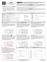
SPECIFICATIONS
All C24EA steamers, with exception of 480V
steamers, are shipped pre-wired for 208/60/3
operation. Steamer heating element wiring change is
required if connecting to 208/60/1, 240/60/1 or
240/60/3 electrical service.
ELECTRICAL SPECIFICATIONS
Volts Phase
C24EA6 C24EA10
Total
KW
Amps
Total
KW
Amps
208 1 16.9 81 25.6 121
240 1 19.0 79 25.6 110
208 3 16.9 48 25.2 72
240 3 19.0 51 25.6 67
480 3 17.2 21 25.6 32
NOTES:
1. Voltage values are @ 60HZ.
2. Heating elements on three phase
machines are not wired as a balanced
load. The amps listed are the
maximum on any leg.
3. Total KW and amps include heat
exchanger elements.
WATER SUPPLY REQUIREMENTS
Supply pressure should be 20-60 psig
In line strainer for supply line
(Supplied)
Total dissolved solids (TDS)* less than 60 ppm
Total alkalinity less than 20 ppm
Silica less than 13 ppm
Total Chloride less than 4.0 ppm
PH factor 6.5 to 8
Undissolved Solids less than 5 microns
*17.1 ppm = 1 grain of hardness
Water hardness below 4 grains/gal requires water
treatment to reduce potential corrosion. Hardness
above 6 grains/gal should be treated by water
conditioner, water softener or in-line treatment.
Water Conditioning
It is recommended that a local water treatment
specialist be consulted before the installation of any
steam generating equipment.
Furnishing the steam generator with properly
conditioned water to reduce scale formation is
important. Scale formation will reduce steam output,
cause premature component failure and shorten
equipment life. Most water supplies contain scale
producing minerals such as calcium and magnesium.
As steam is generated, the minerals remain and
dissolve into the remaining water. As the
concentration of these minerals increases past a
certain point, they precipitate from the water and
coat the inside of the steam generator, heating
elements, thermostat bulbs and water level probes.
Because of the high temperature of these surfaces,
the precipitated minerals bake onto them and
become very difficult to remove.
This phenomenon causes several problems:
1. Reduces the heat transfer efficiency of heating
elements.
2. Causes premature failure of heating elements.
3. Water level probes will give false readings.
4. Temperature sensing bulbs will sense
temperature incorrectly.
These problems are common to any manufacturer's
steamer regardless of design, but they can all be
prevented by furnishing the steam generator with
properly conditioned water. Vulcan recommends the
water contain less than 60ppm of total dissolved
solids (TDS) and have a PH factor between 6.5 to 8.

MODEL C24EA - GENERAL
F35453 (July 2008) Page 4 of 68
Other chemical properties in water supplies can also
affect good steam generation and vary from within
each state and locality.
The water level probes in the steam generator use
ions in the water to detect the water level. Do not use
fully demineralized or de-ionized water since it is
non-conductive and the water level can not be
detected.
NOTE: The use of strainers, or filters will not remove
minerals from the water.
Steamers that operate over a long period of time
without the benefit of properly conditioned water, and
have developed a heavy scale build up, should be
cleaned before connecting to a conditioned water
supply.
REFERENCE MATERIAL
For replacement parts, refer to Catalog of
Replacement Parts F35454.
For operation, cleaning and maintenance
instructions, refer to Installation and Operation
Manual F35430.
LUBRICATION
Component Lubrication Type
All NPT Fittings Pipe Thread Sealant, Loctite 565
Door Handle
Sliding Bracket
Lubriplate 630AA
TOOLS
• Standard set of hand tools.
• VOM with A/C current tester (any quality VOM
with a sensitivity of at least 20K ohms per volt
can be used).
• Anti Static Kit, Part No. TL - 84919.
Special
• Torque Wrench - Capable of measuring
70 in-lbs.
• Aluminum Foil Tape - (McMaster-Carr Part No.
7631A21) or equivalent.
• Single use Constant Tension Band Clamps for
the specific hose size being used. Refer to parts
catalog for part number.
• Pressure Gauge Assembly
• Low Pressure Gauge - 0 to 5 psi.
recommended (Grainger Part No. 2C641).
• Water Hose Coupling - swivel type
(Grainger Part No. 4KG87).
• Reducer Bushing (Grainger Part No.
6MN61).
• Pipe thread sealant (as required).

MODEL C24EA - COVERS AND PANELS
F35453 (July 2008)Page 5 of 68
COVERS AND PANELS
FRONT BASE PANEL
1. Remove screws from the bottom of panel.
2. Pull bottom of panel out and slide down to clear
tabletop cover.
3. Reverse procedure to install.
RIGHT AND LEFT SIDE BASE
PANELS
NOTE: Removal of left side panel is identical to the
procedure for the right side panel.
1. Remove FRONT BASE PANEL.
2. Remove screws from the bottom of panel.
3. Pull bottom of panel out and slide down to clear
tabletop cover.
4. Reverse procedure to install.

MODEL C24EA - COVERS AND PANELS
F35453 (July 2008) Page 6 of 68
REAR BASE PANEL
1. Remove electrical power connection to
machine.
2. Turn off water supply and disconnect plumbing
to machine.
3. Remove screws securing water valves to panel.
4. Remove screws from the bottom of panel.
5. Pull bottom of panel out and slide down to clear
tabletop cover.
6. Reverse procedure to install.
COOKING COMPARTMENT
RIGHT AND LEFT SIDE PANELS
NOTE: Removal of left side panel is identical to the
procedure for the right side panel.
1. Remove screws from the bottom of panel.
2. Pull bottom of panel out and slide down to clear
top cover.
3. Reverse procedure to install.

MODEL C24EA - DOOR
F35453 (July 2008)Page 7 of 68
DOOR
REMOVAL
1. Close door.
2. Remove COOKING COMPARTMENT LEFT
SIDE PANEL as outlined under COVERS AND
PANELS.
3. Remove nuts from upper hinge located inside
front panel.
4. Open door slightly, and while holding door, pull
upper hinge away from front panel.
5. Pull upper hinge out of upper door hinge
bushing.
6. Lift door assembly up and off lower door hinge.
7. Reassemble parts removed in reverse order.
8. Check door for fit and proper sealing of gasket.
GASKET
1. Open door.
2. Remove the shoulder screws and pan pusher
bracket from gasket plate.
3. Remove gasket plate.
4. Remove gasket from inner door panel.
5. Remove RTV from bottom part of inner door
panel. Apply RTV 109 to bottom of door where
shown when assembling gasket to door.
6. Place a small amount of RTV109 into the inner
door panel gasket screw holes before
assembly.
7. Position the new gasket on gasket plate and
reverse procedure to install.

MODEL C24EA - DOOR
F35453 (July 2008) Page 8 of 68
DOOR HANDLE
Removal
1. Open door.
2. Remove screws from top and bottom of door
assembly.
3. Pull outer door housing away from inner door
panel starting at the hinge side of door to
separate the door halves.
NOTE: The smaller radius of the step spacers fit into
the slots of the outer door housing and is used to
provide clearance for handle operation.
4. Remove lock nuts and stepped spacers from
threaded studs of door handle.
Installation
1. Apply Lubriplate 630AA around slots of outer
door housing where step spacers contact
housing.
2. Install door handle into outer door housing such
that hinge side of door housing is to the left and
arrow on handle is pointed upward.
3. Install step spacer with smaller radius toward
handle and door housing. Smaller radius is a
slip fit with outer door housing slot.
4. Install lock nuts and tighten until no gap exists
between handle, step spacer and lock nut. Do
not over-tighten lock nuts.
5. Close inner door panel so that latch mechanism
engages striker on front panel.
6. Install outer door housing onto inner door panel.
7. Align the top and bottom screw holes of outer
door housing with inner door panel.
8. Install screws to secure door halves together.
Apply Loctite 242 to threads of screws before
assembly.
9. Check opening and closing operation of door.

MODEL C24EA - DOOR
F35453 (July 2008)Page 9 of 68
LATCH ASSEMBLY
Removal and Disassembly
1. Separate outer door housing assembly from
inner door panel as outlined under DOOR
HANDLE.
2. Remove screws securing latch assembly to
inner door panel and remove latch mechanism.
3. Remove E-clip from latch assembly pins and
pull pins from latch mechanism.
4. Remove retaining pin from spring pin.
5. Separate sliding bracket from stationary
bracket.
Assembly
1. Apply Lubriplate 630AA to sides of sliding
bracket.
2. Insert spring pin into bottom of sliding bracket.
A. Place spring over spring pin.
3. Assemble sliding bracket into stationary
bracket.
4. While holding head of spring pin against bottom
of sliding bracket, insert spring pin into keeper
hole in bottom of stationary bracket.
A. Secure spring pin in place with retaining
pin.
NOTE: Install pins such that heads of pins will be
facing inward toward hinge side of inner door panel
when latch assembly is installed.
5. Install pins to assemble stationary and sliding
brackets together.
A. Secure pins into position with E-clip.

MODEL C24EA - DOOR
F35453 (July 2008) Page 10 of 68
Installation
1. Install latch assembly onto inner door panel with
spring pin toward bottom of door panel.
A. Apply Loctite 271 to threads of screws
before assembly and secure latch
assembly to inner door panel.
2. Install outer door housing assembly as outlined
under DOOR HANDLE.
3. Check opening and closing operation of door.
4. Check steamer for proper operation and leaks
around door seal.
HINGE BEARINGS
1. Close door.
2. Remove COOKING COMPARTMENT LEFT
SIDE PANEL as outlined under COVERS AND
PANELS.
3. Remove nuts from upper hinge located inside
front panel.
4. Open door slightly, and while holding door, pull
upper hinge away from front panel.
5. Pull upper hinge out of upper door hinge
bearing.
6. Lift door assembly up and off lower door hinge.
7. Pry hinge bearing out from door assembly.
8. Remove outer door housing.
Do not drive bearing into place. The inner
door panel could be damaged. Press bearing into
position.
NOTE: When replacing door hinge bearings, replace
both hinge bearings.
9. Position replacement hinge bearing over hinge
opening in door assembly.
A. Press hinge bearing fully into door
assembly using a C-clamp or equivalent.
10. Reassemble parts removed in reverse order.
11. Check door for fit and proper door gasket
sealing.
DOOR LATCH ADJUSTMENT
Opening a Jammed Door
Should the steamer door jam and cannot
be opened, do not force or pry the door as damage
will occur.
1. Lift up on bottom of door at the handle end to
disengage latch.
A. If door does not open, remove COOKING
COMPARTMENT RIGHT SIDE PANEL as
outlined under COVERS AND PANELS.

MODEL C24EA - DOOR
F35453 (July 2008)Page 11 of 68
B. Locate the striker that catches on door
latch near steam chamber on front panel.
C. Remove the nut from striker and this
should release it from the panel.
D. Open door.
2. Remove striker.
3. Remove any burrs on striker that may cause
latch to stick.
4. Apply Loctite 271 to threads of striker.
5. Reinstall striker with slotted side up. Snug
striker nut. Perform Adjustment, so door will not
jam.
Adjustment
1. Reinstall striker with slot pointing upward and
hand tighten nut only.
2. Close door to center striker in front panel
mounting hole.
3. Open door and check striker slot for horizontal
alignment. The slot on striker must be kept
horizontal in order for door latch to catch
properly and latch.
4. Once proper slot alignment has been set, hold
striker close to its base then tighten the striker
nut. Be careful not to damage striker slot when
tightening or door may not latch properly.
NOTE: Do not over-tighten nut. If over-tightened,
striker may turn and change alignment.
NOTE: If door does not open easily, add shims
between striker and cabinet front. When adding
shims make certain that door gasket seals properly
and steamer does not leak. Remove shims as
necessary until leaking stops.

MODEL C24EA - THERMOSTATS AND HIGH LIMITS
F35453 (July 2008) Page 12 of 68
THERMOSTAT AND HIGH LIMITS
HEAT EXCHANGER HIGH LIMIT
1. Turn off machine to drain steam generator.
Allow steamer to complete drain cycle.
2. Remove RIGHT SIDE BASE PANEL as
outlined under COVERS AND PANELS.
3. Disconnect electrical lead wires from heat
exchanger high limit.
4. Loosen hose clamps securing heat exchanger
high limit to the heat exchanger surface.
5. Remove heat exchanger high limit.
6. Reassemble parts removed in reverse order.
7. Check steamer for proper operation.
STEAM GENERATOR HIGH LIMIT
Removal
1. Turn off machine to drain steam generator.
Allow steamer to complete drain cycle.
A. Turn off water supply.
2. Remove FRONT BASE PANEL as outlined
under COVERS AND PANELS.
3. Remove heating element (1HTR) from steam
generator as outlined under HEATING
ELEMENTS AND CONTACTORS.
4. Fully loosen capillary tube compression nut and
slide it away from heating element.
5. Remove capillary tube mounting nut from
heating element mounting plate.
6. Disconnect electrical wiring to high limit.
7. Remove high limit from the rear of low voltage
control box.

MODEL C24EA - THERMOSTATS AND HIGH LIMITS
F35453 (July 2008)Page 13 of 68
8. Remove capillary tube from heating element.
Installation
1. Route capillary bulb through the opening in
heating element mounting plate. Ensure there
are no sharp bends in capillary tubing while
installing.
A. Insert capillary bulb into the holding tube
on heating element.
2. Apply pipe thread sealant to threads then install
large capillary tube mounting nut.
A. Ensure capillary bulb is centered in the
holding tube. Tighten the capillary tube
compression nut.
3. Install heating element with a new gasket.
Torque mounting nuts to 70 in-lbs and tighten
using an alternating pattern.
4. Secure high limit to low voltage control box then
coil excess capillary tube length near the high
limit.
5. Check steamer for proper operation and leaks
around heating element gasket and high limit
capillary tube nuts.
CONDENSATE THERMOSTAT
1. Turn off machine to drain steam generator.
Allow steamer to complete drain cycle.
A. Turn off water supply.
2. Remove RIGHT SIDE BASE PANEL as
outlined under COVERS AND PANELS.
3. Disconnect electrical wiring to condensate
thermostat.
4. Remove condensate thermostat from the rear of
drain box.
5. Reassemble parts removed in reverse order.
Apply pipe thread sealant to threads of
thermostat before assembly.
6. Check steamer for proper operation and leaks
around condensate thermostat.
RIGHT SIDE SHOWN
REAR OF DRAIN BOX SHOWN

MODEL C24EA - TIMERS
F35453 (July 2008) Page 14 of 68
TIMERS
REMOVAL AND REPLACEMENT
NOTE: When the timer reaches zero, an external
buzzer will sound and steam will stop entering the
cooking compartment. The constant steam setting
allows for continuous steam operation.
1. Remove COOKING COMPARTMENT RIGHT
SIDE PANEL as outlined under COVERS AND
PANELS.
2. Note electrical connections then disconnect
wiring from timer being serviced.
3. Pull knob from timer shaft.
A. Remove rotary shaft seal from timer shaft
then remove timer from front panel.
B. Inspect rotary shaft seal. Replace if
damaged, worn or signs of moisture
migration into control area around timer
shaft is evident.
4. Reverse procedure to install.
5. Check steamer for proper operation.
UPPER COMPARTMENT SHOWN

MODEL C24EA - HEATING ELEMENTS AND CONTACTORS
F35453 (July 2008)Page 15 of 68
HEATING ELEMENTS AND CONTACTORS
REMOVAL AND REPLACEMENT
Heating Elements
1. Turn off machine to drain steam generator.
Allow steamer to complete drain cycle.
A. Turn off water supply.
2. Remove FRONT BASE PANEL as outlined
under COVERS AND PANELS.
3. Remove top screw securing cover to high
voltage box.
4. Note electrical connections for the heating
element being replaced then disconnect heating
element lead wires from contactors.
5. Remove mounting nuts and lock washers
securing heating element to steam generator.
A. If replacing heating element (1HTR),
remove STEAM GENERATOR HIGH
LIMIT.
B. Pull heating element out of steam
generator.
6. Reassemble parts removed in reverse order.
Torque mounting nuts to 70 in-lbs and tighten
using an alternating pattern.
NOTE: When installing heating element 2HTR or
3HTR, install pipe plug in the center of heating
element mounting plate. Apply pipe thread sealant to
threads before assembly. Use a new gasket
whenever installing a heating element.
NOTE: Refer to STEAM GENERATOR HIGH LIMIT
for proper placement of capillary bulb.
7. Check steamer for proper operation and leaks
around heating element.
HEATING ELEMENT (1HTR) WITH STEAM
GENERATOR HIGH LIMIT SHOWN

MODEL C24EA - HEATING ELEMENTS AND CONTACTORS
F35453 (July 2008) Page 16 of 68
Contactors
1. Turn off machine to drain steam generator.
Allow steamer to complete drain cycle.
2. Remove FRONT BASE PANEL as outlined
under COVERS AND PANELS.
3. Remove top screw securing cover to high
voltage box.
4. Note electrical connections for the contactor
being replaced then disconnect lead wires from
contactor terminals and coil.
5. Remove screws securing contactor to high
voltage control box then remove contactor.
6. Reassemble parts removed in reverse order.
7. Check steamer for proper operation.
HEATING ELEMENTS
DIAGNOSTIC CHECK
1. Check voltage across heating element lead
wires at the limiting and regulating contactor
terminals and verify against data plate.
A. If voltage is correct, check current draw
(step 2).
B. If voltage is not correct, check the
following:
1) Voltage supply to steamer.
2) Fuses or breaker blown.
3) Power to contactor coils.
4) Contactors not pulling in (mechanical
problem).
2. Check current draw (amps) through heating
element lead wires using an amp clamp meter.
NOTE: Checking current draw is the preferred
method over a resistance check when an amp clamp
meter is available.
A. If current is correct, then heating element is
ok. See table for proper values.
B. If current is not correct, turn power switch
off and disconnect power to machine.
1) Install a replacement heating element.

MODEL C24EA - HEATING ELEMENTS AND CONTACTORS
F35453 (July 2008)Page 17 of 68
3. If unable to check current draw, a resistance check may indicate a malfunctioning element.
A. Turn power switch off and disconnect power to machine.
B. Disconnect heating element lead wires and check the individual element resistance using a VOM.
C. If resistance readings are not correct, replace heating element.
4. Check steamer for proper operation.
VOLTAGE
KW PER
ELEMENT
CURRENT PER
ELEMENT
RESISTANCE PER
ELEMENT (OHMS)
208
1
8.0 12.8 16.2
240
1
10.5 14.8 16.2
480
2
8.0 9.6 28.8
208
1
8.0 12.8 16.2
240
1
10.5 14.8 16.2
480
2
8.0 9.6 28.8
1
Dual voltage elements.
2
480V elements are connected in Wye configuration for 277V across each element.
NOTE: Values in table are nominal. Tolerance is ±10 %.

MODEL C24EA - HEAT EXCHANGER ELEMENTS AND RELAYS
F35453 (July 2008) Page 18 of 68
HEAT EXCHANGER ELEMENTS AND RELAYS
REMOVAL AND REPLACEMENT
Heat Exchanger Elements
1. Turn off machine to drain steam generator.
Allow steamer to complete drain cycle.
A. Turn off water supply.
2. Remove FRONT BASE PANEL and RIGHT
SIDE BASE PANEL as outlined under COVERS
AND PANELS.
3. Note electrical connections for the heat
exchanger element being replaced then
disconnect lead wires from heat exchanger
relay and contactor.
4. Remove motorized control assembly from
delime valve. Rotate the assembly CCW
approximately 1/8 turn to disengage from
delime valve.
NOTE: When installing, align the flat on delime valve
stem and the locking pins on delime valve to the
motorized control assembly.
NOTE: The two electrical plugs on the motorized
control assembly are identical. Note location of
electrical wiring if disconnecting from motorized
control assembly. If the electrical plugs not
connected correctly, the motorized delime valve will
not function.
5. Remove heat exchanger element from heat
exchanger.
NOTE: To access heat exchanger element (1),
remove heat exchanger element (2) and the 3/8"
vent tube on vacuum relief valve (outlet side).

MODEL C24EA - HEAT EXCHANGER ELEMENTS AND RELAYS
F35453 (July 2008)Page 19 of 68
6. Reassemble parts removed in reverse order.
Apply pipe thread sealant to threads of heat
exchanger element before assembly.
7. Check steamer for proper operation and leaks
around heat exchanger element.
Heat Exchanger Relays (K10, K12)
1. Turn off machine to drain steam generator.
Allow steamer to complete drain cycle.
2. Remove FRONT BASE PANEL as outlined
under COVERS AND PANELS.
3. Remove top screw securing cover to high
voltage control box.
4. Note electrical connections for the heat
exchanger relay being replaced then disconnect
lead wires from relay terminals and coil.
5. Remove screws securing heat exchanger relay
to high voltage control box then remove relay.
6. Reassemble parts removed in reverse order.
7. Check steamer for proper operation.
HEAT EXCHANGER ELEMENTS
DIAGNOSTIC CHECK
1. Check voltage across heat exchanger element
lead wires at the limiting and regulating
contactor terminals and verify against data
plate.
A. If voltage is correct, check current draw
(step 2).
B. If voltage is not correct, check the
following:
1) Voltage supply to steamer.
2) Fuses or breaker open.
3) Heat exchanger relay (K10) (heat
exchanger element 1) or heat
exchanger relay (K12) (heat
exchanger element 2).
4) Power to contactor coils.
5) Contactors not pulling in (mechanical
problem)
2. Check current draw (amps) through heat
exchanger element lead wires using an amp
clamp meter.
NOTE: Checking current draw is the preferred
method over a resistance check when an amp clamp
meter is available.
A. If current is correct, then heat exchanger
element is ok. See table for proper values.
B. If current is not correct, turn power switch
off and disconnect power to machine.
1) Install replacement heat exchanger
element.

MODEL C24EA - HEAT EXCHANGER ELEMENTS AND RELAYS
F35453 (July 2008) Page 20 of 68
3. If unable to check current draw, a resistance check may indicate a malfunctioning element.
A. Turn power switch off and disconnect power to machine.
B. Disconnect heat exchanger element lead wires and check resistance using a VOM.
C. If resistance is not correct, replace heat exchanger element.
4. Check steamer for proper operation.
MODEL VOLTAGE
WATTS PER
ELEMENT
CURRENT PER
ELEMENT
RESISTANCE PER
ELEMENT (OHMS)
C24EA6
208
1
450 2.20 96.1
240
1
600 2.50 96.0
480
2
600 2.20 128.0
C24EA10
208
1
600 2.90 72.1
240
1
800 3.30 72.0
480
2
800 2.90 95.9
1
Dual voltage elements.
2
480V Elements are connected in Wye configuration for 277V across each element.
NOTE: Values in table are nominal. Tolerance is ±10 %.
/