
RANGE HOOD - User instructions
HOTTE DE CUISINE - Notice d’utilisation
CAMPANA EXTRACTORA - Manual de utilización
USA
F
E
XOT48KS
XOT1836KS
XOT1848KS
NEED HELP?
Call our ventilation experts toll free al 800-966-8300
AVEZ-VOUS BESOIN D’AIDE ?
Contactez nos experts au numéro gratuit 800-966-8300
¿NECESITA AYUDA?
Póngase en contacto con nuestros expertos a través del número gratis 800-966-8300

Proof of original purchase date and invoice is needed to obtain
service under warranty.
Limited 2 Year Warranty.
For 2 years from the original date of purchase, we will provide, free
of charge, parts and service labor in your home to repair or replace
any part of the hood that fails because of a manufacturing defect.
The warranty is extended to the original purchaser for products
purchased for ordinary home use in North America.
Should you require service for your XO product call a product
service specialist at 800.966.8300
Improper Installation.
Service trips to the home to teach you how to use the product.
Resetting circuit breakers.
Damage caused after delivery.
EXPECT MORE FROM XO
When buying any XO appliance
you can be condent
you have purchased a high quality,
innovative, and stylish product,
from a company who cares about you.
XO Hood Warranty
What is covered
What is not covered

- 3 -
IMPORTANT SAFETY INSTRUCTIONS.
FOR RESIDENTIAL USE ONLY.
READ AND SAVE THESE INSTRUCTIONS.
PLEASE READ ENTIRE INSTRUCTIONS BEFORE PROCEEDING.
IMPORTANT: Save these Instructions for the Local Electrical Inspectors use.
INSTALLER: Please leave these Instructions with this unit for the owner.
OWNER: Please retain these instructions for future reference.
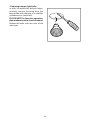
Take care when using cleaning agents or detergents.
Suitable for use in household cooking area.
WARNING - To reduce the risk of re or electric shock, do not use this fan with any
Solid-State Speed Control Device.
CAUTION - To reduce risk of re and to properly exhaust air, be sure to duct air outside
– Do not vent exhaust air into spaces within walls or ceilings or into attics, crawl spaces,
or garages.
CAUTION - For general ventilating use only. Do not use to exhaust hazardous or
explosive materials and vapors.
CAUTION - To avoid motor bearing damage and noisy and/or unbalanced impellers,
keep drywall spray, construction dust, etc. o power unit.
CAUTION - Please read specication label on product for further information and
requirements.
WARNING – TO REDUCE THE RISK OF FIRE, ELECTRIC SHOCK, OR INJURY TO PERSONS,
OBSERVE THE FOLLOWING:
A. Use this unit only in the manner intended by the manufacturer. If you have questions,
contact the manufacturer.
B. Before servicing or cleaning unit, switch power o at service panel and lock the service
disconnecting means to prevent power from being switched on accidentally. When
the service disconnecting means cannot be locked, securely fasten a prominent warning
device, such as a tag, to the service panel.
WARNING - TO REDUCE THE RISK OF A RANGE TOP GREASE FIRE:
A. Never leave surface units unattended at high settings. Boilovers cause smoking and
greasy spillovers that may ignite. Heat oils slowly on low or medium settings.
B. Always turn hood ON when cooking at high heat or when ambeing foods (i.e. Crepes
ENGLISH
USA

- 4 -
Suzette, Cherries Jubilee, Peppercorn Beef Flambè).
C. Clean ventilating fans frequently. Grease should not be allowed to accumulate on fan
or lter.
D. Use proper pan size. Always use cookware appropriate for the size of the surface
element.
E. Keep fan, lters and grease laden surface clean.
F. Use high range setting on range only when necessary.Heat oil slowly on low to medium
setting.
G. Don’ t leave range unattended when cooking.
H. Always use cookware and utensils appropriate for the type and amount o food being
prepared.
WARNING – TO REDUCE THE RISK OF INJURY TO PERSONS IN THE EVENT OF A RANGE
TOP GREASE FIRE, OBSERVE THE FOLLOWING
a
:
A. SMOTHER FLAMES with a close-tting lid, cookie sheet, or metal tray, then turn o
the burner. BE CAREFUL TO PREVENT BURNS. If the ames do not go out immediately,
EVACUATE AND CALL THE FIRE DEPARTMENT.
B. NEVER PICK UP A FLAMING PAN – You may be burned.
C. DO NOT USE WATER, including wet dishcloths or towels – a violent steam explosion
will result.
D. Use an extinguisher ONLY if:
1. You know you have a Class ABC extinguisher, and you already know how to operate it.
2. The re is small and contained in the area where it started.
3. The re department is being called.
4. You can ght the re with your back to an exit.
a
Based on “kitchen resafety tips” published by NFPA.
Proper maintenance of the Range Hood will assure proper performance of the unit.
INSTALLATION INSTRUCTIONS
WARNING – TO REDUCE THE RISK OF FIRE, ELECTRIC SHOCK, OR INJURY TO PERSONS,
OBSERVE THE FOLLOWING:
A. Installation work and electrical wiring must be done by qualied person(s) in accordance
with all applicable codes and standards, including re-rated construction.
B. Sucient air is needed for proper combustion and exhausting of gases through the
ue (chimney) of fuel burning equipment to prevent back drafting. Follow the heating
equipment manufacturer’s guideline and safety standards such as those published by
the National Fire Protection Association (NFPA), and the American Society for Heating,
Refrigeration and Air Conditioning Engineers (ASHRAE), and the local code authorities.
C. When cutting or drilling into wall or ceiling, do not damage electrical wiring and
other hidden utilities.
D. Ducted fans must always be vented to the outdoors.
E. This unit must be grounded.

- 5 -
WARNING - TO REDUCE THE RISK OF FIRE, USE ONLY METAL DUCTWORK.
WARNING - UNDER CERTAIN CIRCUMSTANCES DOMESTIC APPLIANCES MAY BE
DANGEROUS.
A. Do not check lters with hood working.
B. Do not touch the lamps after a prolonged use of the appliance.
C. No food must be cooked ambè underneath the hood.
D. The use of an unprotected ame is dangerous for the lters and could cause res.
E. Watch constantly the fried food in order to avoid the cooking oil ares up.
F. Before performing any mainteinance operation, disconnect the hood from the electrical
service.
The manufacturers will not to accept any responsability for eventual damages, because
of failure to observe the above instructions.

- 6 -
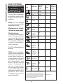
Installation Preparation
Duct
Piece:
Dimensions:
Equivalent
Number
Length*:
Quantity
Used:
Total
Equivalent
Length:
Round, straight
1 ft. (per foot
lenhgth)
3-1/4" x 10"
straight
1 ft. (per foot
lenhgth)
90° elbow 12 ft.
45° elbow 7 ft.
3-1/4" x 10"
3-1/4" x 12"
90° elbow
14 ft.
10 ft.
3-1/4" x 10"
3-1/4" x 12"
45° elbow
8 ft.
6 ft.
3-1/4" x 10"
3-1/4" x 12"
90° elbow
33 ft.
24 ft.
6" round to
rectangular
2 ft.
Rectangular to
8" round
2 ft.
3-1/4" x 10"
3-1/4" x 12"
6" round to
rectangular
transition 90°
elbow
4 ft.
4 ft.
3-1/4" x 10"
3-1/4" x 12"
Rectangular to
6" transition
90° elbow
4 ft.
4 ft.
Round wall cap
with dramper
24 ft.
3-1/4" x 10"
3-1/4" x 12"
Rectangular
wall cap with
dramper
24 ft.
18 ft.
Round roof cap 33 ft.
*Actual length of straight duct plus duct
fitting equivalent. Equivalent length of duct
pieces are based on actual tests conducted
by GE Evaluation Engineering and reflect
requirements for good venting performance
with any ventilation hood.
Total Duct Run =
DUCT FITTINGS:
This Hood Must Use an
8" Round Duct. It Can
Transition to 3-1/4" x 10"
or 3-1/4" x 12" Duct.
Use this chart to compute
maximum permissible
lengths for duct runs to
outdoors.
NOTE: Do not exceed
maximum permissible
equivalent lengths!
Maximum duct length:
100 feet for range hoods.
Flexible ducting:
If flexible metal ducting is
used, all the equivalent feet
values in the table should be
doubled. The exible metal
duct should be straight and
smooth and extended as
much as possible.
DO NOT use exible plastic
ducting.
NOTE: Any home ventilation
system, such as a ventilation
hood, may interrupt the
proper ow of combustion
air and exhaust required
by replaces, gas furnaces,
gas water heaters and
other naturally vented
systems. To minimize the
chance of interruption
of such naturally vented
systems, follow the heating
equipment manufacturer’s
guidelines and safety
standards such as those
published by NFPA.

- 7 -
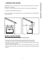
WARNING FIRE HAZARD
NEVER exhaust air or terminate duct work into spaces between walls, crawl spaces,
ceiling, attics or garages.
All exhaust must be ducted to the outside, unless using the recirculating option.
Use single wall rigid Metal ductwork only.
Fasten all connections with sheet metal screws and tape all joints w/ certied Silver
Tape or Duct Tape.
INSTALL THE DUCTWORK:
NOTE: to reduce the risk of re, use only metal ductwork.
1. Decide where the ductwork will run between the hood and the outside.
2. A straight, short duct run will allow the hood to perform most eciently.
3. Long duct runs, elbows, and transitions will reduce the performance of the hood.
Use as few of them as possible.
4. Install a roof or wall cap. Connect 8" round metal ductwork to cap and work
back towards hood location. Use duct tape to seal the joints between ductwork
sections.
Installation - Ducting Options

- 8 -
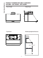
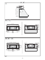
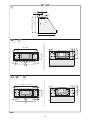
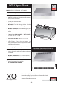
Min 27" - Max 32"
36"
8"
11" - 18"
1-5/16"
12"
8"
5-5/8"
3"
36" - 48"
22"
Hood Specications
PRODUCT DIMENSIONS AND CLEARANCE
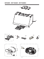
XOT48KS - XOT1836KS - XOT1848KS:
Front of hood
Side of hood
Top of hood Mounting height and clearance:

- 9 -
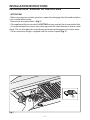
INSTALLATION INSTRUCTIONS
INSTALLATION VENTED TO THE OUTSIDE
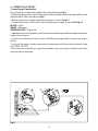
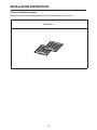
1. ATTENTION!
- Before carrying out assembly operations, open the packaging, take the hood and place
it on a comfortable surface.
- Remove the anti-grease lter/s (Fig.1).
- If the appliance id to be mounted in DUCTING version, prepare the air evacuation hole.
- It is recommended to use an air evacuation pipe with the same diameter as the air outlet
ange. The use of a reduction could decrease product performance and increase noise.
- The air evacuation ange is supplied with the circular shape X (Fig.1).
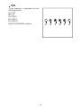
Fig.1
X

- 10 -
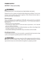
POWER SUPPLY:
IMPORTANT - (Please read carefully)
WARNING:
FOR PERSONAL SAFETY, THIS APPLIANCE MUST BE PROPERLY GROUNDED.
Remove house fuse or open circuit breaker before beginning installation. Do not use an
extension cord or adapter plug with this appliance. Follow National electrical codes or
prevailing local codes and ordinances.
Electrical supply:
These vent hoods must be supplied with 120V, 60Hz, and connected to an individual,
properly grounded branch circuit, and protected by a 15 or 20 amp circuit breaker or
time delay fuse.
tWiring must be 2 wire with ground.
tIf the electrical supply does not meet the above requirements, call a licensed
electrician before proceeding.
tRoute house wiring as close to the installation location as possible, in the ceiling or back
wall. Refer to Wiring Locations on page 11.
tConnect the hood wiring to the house wiring in accordance with local codes.
Grounding instructions:
The grounding conductor must be connected to a grounded metal, permanent wiring
system, or an equipment-grounding terminal or lead on the hood.
WARNING: the improper connection of the equipment-grounding conductor
can result in a risk of electric shock. Check with a qualified electrician or service
representative if you are in doubt whether the appliance is properly grounded.

- 11 -
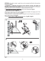
2. CONNEC T ELECTRIC AL:
t1PXFS4VQQMZ$POOFDUJPO
For connection to the power supply refer to the following Fig.2:
1. Break and remove the small circular metal sheet positioned in the rear part of the hood,
with the aid of a at screw driver Fig.2.1.
2. Remove the power supply lid by loosening the 2 screws A Fig.2.2.
3. Connect the wires of the hood to those of the power supply as described Fig.2.3:
BLACK = L line
WHITE = N neutral
GREEN/YELLOW = G ground.
- A double-pole switch properly rated must be installed to provide the range hood power
supply disconnection.
- Connect the electrical conduit to the Field Wiring Compartment using listed onduit
ttings.
- Carry out the power supply connection in accordance with the national electric code,
ANSI/NFPA 70-1999.
4. Insert the wires into the box, then close the box cover, securing it using the screws that
were previously removed.
Fig.2
A
A
1
2
3

- 12 -
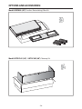
OPTIONAL: the electric power supply box can be removed and xed in the position
indicated in Fig.3A.
WARNING - TO REDUCE THE RISK OF FIRE, ELECTRIC SHOCK, OR INJURY TO
PERSONS, OBSERVE THE FOLLOWING: Before connecting the appliance to the power
supply network, the electric plant box must be positioned in the seat.
To move the electric power supply box, refer to that indicated in Fig.3A:
1. Loosen the two screws C Fig.3A.1.
2. Break and remove the small circular metal sheet positioned in the upper part of the
hood, with the aid of a at screwdriver Fig.3A.2.
3. Take the electric connection box and x it using the 2 screws C, previously removed, in
the position indicated in Fig.3A.3.
4. For the electric power supply connection refer to Fig.3B.2-Fig.3B.3.
Fig.3
A
A
1
2
3
C
2
1
C
C
A
B
3

- 13 -
tThe appliance must be installed at a minimum height of 27" from an electric cooker stove,
or 32" from gas or combined cooker stoves. If a connection ductwork composed of two
parts is used, the upper part must be placed outside the lower part. Do not connect the
range hood exhaust duct air to the same duct air used to exhaust hot air or fumes from
other appliances other than electrical.
Min 27" - Max 32"
36"
3. CONNEC T THE DUCT WORK:

- 14 -
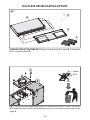
tThis product can be installed in 2 dierent ways:
- Mounting the hood in the lower part of the shelf:
1 type installation Fig.4.
- Mounting the hood on the wall:
2 type installation Fig.4.
Fig.4
1
2
A
B
4
A
B
1

- 15 -
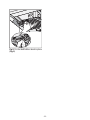
t.PVOUJOHUIFIPPEJOUIFMPXFSQBSUPGUIFTIFMG'JH"
- Check that the screws used that are not supplied with the product are suitable for the
type of object.
- Position the xing template on the lower part of the shelf 'JH#, (considering the
minimum distance from the cooker top).
- Make 6 holes in the shelf respecting the measurements indicated 'JH$.
- Fix the 4 screws A without tightening them completely.
- Position the hood under the pensile, push towards the wall up to end run, tighten/fasten
the 4 screws A and x it denitively using the 2 safety screws B.
'JH
A
B
A
B
4
B
A
B
A

- 16 -
'JH
C
H
I
9"
47-15/16"
9/16"
9/16"
3"
3"
2-1/4"
2"
7"
4"
2"
3-1/2"
H
I
15-15/16"
35-15/16" - 47-15/16"
9/16"
9/16"
3"
3"
2-1/4"
2"
7"
4"
2"
3-1/2"
36" 48"
22"
3"
11" - 18"
12-3/8" - 19-3/8"
12"
5-5/8"
8"
48"
11"
36" - 48" 18"

- 17 -
t.PVOUJOHUIFIPPEPOUIFXBMM'JH"
Position the xing template on the wall (Fig.6B), (considering the minimum distance from
the cooker top).
- Make 4 holes respecting the measurement indicated in the gures (Fig.6C).
- Fix the 2 upper screws A without tightening them completely along with the plugs.
- Hang the hood on the wall, aligning it in a horizontal position and tighten/fasten the 2
screws A. When it has been regulated, x it denitively using the 2 safety screws B.
For the various installations use screws and screw anchors suited to the type of wall (e.g.
reinforced concrete, plasterboard, etc.). If the screws and screw anchors are provided
with the product, check that they are suitable for the type of wall on which the hood is
to be xed.
tLimited to installation on plasterboard walls: make sure that the screws are xed to the
wall support elements. If this is not the case, install a support structure made up from 2
by 4 inch cross members in correspondence with the screw anchorage points.
Fig.6
A
B
A
B
1
B
A
B
A

- 18 -
C
H
I
9"
47-15/16"
9/16"
9/16"
3"
3"
2-1/4"
2"
7"
4"
2"
3-1/2"
H
I
15-15/16"
35-15/16" - 47-15/16"
9/16"
9/16"
3"
3"
2-1/4"
2"
7"
4"
2"
3-1/2"
36" 48"
22"
3"
11" - 18"
12-3/8" - 19-3/8"
12"
5-5/8"
8"
48" 11"
36" - 48" 18"
Fig.6

- 19 -
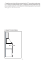
CONNECTION DIAGRAM:
Wall Cutout for Horizontal Ducting
Viewed from Front
11-5/8" (36" - 48")
3-1/4"
Ceiling Cutout for Vertical Ducting
Viewed from Above
BACK OF THE CABINET
11-5/8
" (36" - 48")
3-9/16"
5-5/8"
36" 48"
Electrical
Electrical
BOTTOM OF THE CABINET
8-1/16"

- 20 -
48"
d
c
a
b
X
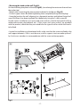
Fig.1: Take the circular shape X and fasten it to the hood using the 7 screws. To convert
this model from the sunction to the ltering version, it is not necessary to use the circular
shape X.
CARBON FILTER KIT XORFK09 (48"): We have an air diverter A, 7 screws B, 4 rectangular
lters C and the bracket D.
DUCTLESS RECIRCULATING OPTION:
Page is loading ...
Page is loading ...
Page is loading ...
Page is loading ...
Page is loading ...
Page is loading ...
Page is loading ...
Page is loading ...
Page is loading ...
Page is loading ...
-
 1
1
-
 2
2
-
 3
3
-
 4
4
-
 5
5
-
 6
6
-
 7
7
-
 8
8
-
 9
9
-
 10
10
-
 11
11
-
 12
12
-
 13
13
-
 14
14
-
 15
15
-
 16
16
-
 17
17
-
 18
18
-
 19
19
-
 20
20
-
 21
21
-
 22
22
-
 23
23
-
 24
24
-
 25
25
-
 26
26
-
 27
27
-
 28
28
-
 29
29
-
 30
30


Ask a question and I''ll find the answer in the document
Finding information in a document is now easier with AI
Related papers
Other documents
-
ZANKER ZK60X User manual
-
Hoover HSD6MGPP-EGY User manual
-
Bertazzoni K90 HD 2X Installation guide
-
Bertazzoni KU122 PRO 2 X Installation guide
-
Forte LUCCA Under Cabinet Range Hood User manual
-
Bertazzoni KU90 PRO 1 X Installation guide
-
Zanussi ZT630T User manual
-
Smeg KPF36UX User manual
-
Smeg KTU36WH User manual
-
Smeg KUC24X User manual