Page is loading ...

R-41-04-010117
6VXE+
USER'S MANUAL
1. System power on by PS/2 Mouse: First, enable this function
in CMOS Setup, then you can power on the system by double
clicking the right or left button of your PS/2 Mouse.
2. System power on by Keyboard: If your ATX power supply
supports larger than 300 mA 5V Stand-By current (depends
on the specification of keyboards), you can power on your
system by entering password from the keyboard after setting
the “Keyboard power on” password in CMOS Setup.
3. Supports 3 steps ACPI LED.
4. Modem Ring-On. (COM A , B).
5. Wake-Up on LAN. (The ATX power supply supports larger
than 720 mA 5V Stand-By current)
For Intel Pentium
II / !!! / Celeron
TM
Processor MAINBOARD
REV. 4.1 Fourth Edition


6VXE+
1
The author assumes no responsibility for any errors or omissions which may
appear in this document nor does it make a commitment to update the
information contained herein.
Third-party brands and names are the property of their respective owners.
Sound Blaster is a registered trademark of Creative Technology Ltd in the
United States and certain other countries. Sound Blaster-LINK and SB-LINK are
trademarks of Creative Technology Ltd.
Jan 17, 2001 Taipei, Taiwan

Quick Installation Guide
2
I. Quick Installation Guide :
CPU SPEED SETUP
The system bus speed is selectable between 66 / 100 / 133MHz. The user can
select the system bus speed from Dip switch SW1 and jumper JP15 , change
the Dip switch SW2 selection to set up the CPU speed for 233 - 800MHz
processor.
Set System Bus Speed
SW1:
CPU JP15 1 2 3 4
66 ON ON OFF OFF ON
75 ON ON ON OFF ON
83 ON ON OFF ON ON
100 ON OFF OFF OFF OFF
112 ON OFF ON OFF OFF
124 OFF OFF OFF ON OFF
133 OFF OFF OFF OFF OFF
140 OFF OFF ON ON OFF
150 OFF OFF ON OFF OFF
The CPU speed MUST match with the frequency RATIO. It will cause
system hanging up if the frequency RATIO is higher than that of CPU.
SW2:
DIP SWITCH
FREQ. RATIO
1 2 3 4
X 3
ON OFF ON ON
X 3.5
OFF OFF ON ON
X 4
ON ON OFF ON
X 4.5
OFF ON OFF ON
X 5
ON OFF OFF ON
X 5.5
OFF OFF OFF ON
X 6
ON ON ON OFF
X 6.5
OFF ON ON OFF
X 7
ON OFF ON OFF
X 7.5
OFF OFF ON OFF
X 8
ON ON OFF OFF
X 8.5
OFF ON OFF OFF
X 9
ON OFF OFF OFF
X 9.5
OFF OFF OFF OFF

6VXE+
3
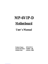
For 133MHz Jumper Setting:
CPU
VIA
82C693
VIA
82C596B
6VXE
1
Pin No. Function
1-2 close For 100 MHz
2-3 close Auto Frequency
1-2-3 open For 133 MHz
JP12
CPU JP15
66 ON
100 ON
133 OFF
JP15
Note: We don’t recommend you to set up your system speed to 75, 83,
112, 124, 140, 150 MHz because these frequencies are not the
standard specifications for CPU, Chipset and most of the
peripherals. Whether your system can run under 75, 83, 112, 124,
140, 150 MHz properly will depend on your hardware
configurations: CPU, SDRAM, Cards, etc.
☞ The black part in the picture is the white extruding piece of the
DIP switch.
1. Pentium
II /Celeron 233 / 66 MHz FSB
CPU
VIA
82C693A
VIA
82C596B
6VXE
ON
OFF
SW 2
123
4
ON
OFF
SW 1
1234

Quick Installation Guide
4
2. Pentium
II /Celeron 266 / 66 MHz FSB
3. Pentium
II /Celeron 300/Celeron 300A / 66 MHz FSB
4. Pentium
II /Celeron 333 / 66 MHz FSB
5. Pentium
II /Celeron 366 / 66MHz FSB
6. Pentium
II /Celeron 400 / 66MHz FSB
7. Pentium
II /Celeron 433 / 66MHz FSB
SW2
ON
4 3 2 1
OFF
SW1
ON
4 3 2 1
OFF
SW2
ON
4 3 2 1
OFF
SW1
ON
4 3 2 1
OFF
SW2
ON
4 3 2 1
OFF
SW1
ON
4 3 2 1
OFF
SW2
ON
4 3 2 1
OFF
SW1
ON
4 3 2 1
OFF
SW2
ON
4 3 2 1
OFF
SW2
ON
4 3 2 1
OFF
SW1
ON
4 3 2 1
OFF
SW1
ON
4 3 2 1
OFF

6VXE+
5
8. Pentium
II /Celeron 466 / 66MHz FSB
9. Pentium
II /Celeron 500 / 66MHz FSB
10. Pentium
II /Celeron 533 / 66MHz FSB
11. Pentium
II /Celeron 566 / 66MHz FSB (Reserve)
12. Pentium
II 350 / 100 MHz FSB
13. Pentium
II 400 / 100 MHz FSB
SW2
ON
4 3 2 1
OFF
SW1
ON
4 3 2 1
OFF
SW2
ON
4 3 2 1
OFF
SW1
ON
4 3 2 1
OFF
SW2
ON
4 3 2 1
OFF
SW1
ON
4 3 2 1
OFF
SW2
ON
4 3 2 1
OFF
SW1
ON
4 3 2 1
OFF
SW2
ON
4 3 2 1
OFF
SW1
ON
4 3 2 1
OFF
SW2
ON
4 3 2 1
OFF
SW1
ON
4 3 2 1
OFF

Quick Installation Guide
6
14. Pentium
II/!!! 450 / 100 MHz FSB
15. Pentium
II/!!! 500 / 100 MHz FSB
16. Pentium
II/!!! 550 / 100 MHz FSB
17. Pentium
II/!!! 600 / 100 MHz FSB
18. Pentium
II/!!! 650 / 100 MHz FSB
19. Pentium
II/!!! 700 / 100 MHz FSB
SW2
ON
4 3 2 1
OFF
SW1
ON
4 3 2 1
OFF
SW2
ON
4 3 2 1
OFF
SW1
ON
4 3 2 1
OFF
SW2
ON
4 3 2 1
OFF
SW1
ON
4 3 2 1
OFF
SW2
ON
4 3 2 1
OFF
SW2
ON
4 3 2 1
OFF
SW1
ON
4 3 2 1
OFF
SW1
ON
4 3 2 1
OFF
SW2
ON
4 3 2 1
OFF
SW1
ON
4 3 2 1
OFF

6VXE+
7
20. Pentium
II/!!! 750 / 100 MHz FSB
21. Pentium
II/!!! 800 / 100 MHz FSB
22. Pentium
II/!!! 850 / 100 MHz FSB (Reserve)
23. Pentium
!!! 533 / 133 MHz FSB
24. Pentium
!!! 600 / 133 MHz FSB
SW2
ON
4 3 2 1
OFF
SW1
ON
4 3 2 1
OFF
SW2
ON
4 3 2 1
OFF
SW1
ON
4 3 2 1
OFF
SW2
ON
4 3 2 1
OFF
SW1
ON
4 3 2 1
OFF
SW2
ON
4 3 2 1
OFF
SW1
ON
4 3 2 1
OFF
SW2
ON
4 3 2 1
OFF
SW1
ON
4 3 2 1
OFF

Quick Installation Guide
8
25. Pentium
!!! 667 / 133 MHz FSB
26. Pentium
!!! 733 / 133 MHz FSB
We don’t recommend you to setup your CPU ratio above 8 nth, it
doesn’t support now.
II. Jumper setting :
SPK : Speaker Connector
CPU
6VXE+
VIA
82C693A
VIA
82C596B
+
1
1
+
Pin No. Function
1 VCC
2 NC
3 NC
4 Data
SW2
ON
4 3 2 1
OFF
SW1
ON
4 3 2 1
OFF
SW2
ON
4 3 2 1
OFF
SW1
ON
4 3 2 1
OFF

6VXE+
9
RST : Reset Switch
CPU
6VXE+
VIA
82C693A
VIA
82C596B
Pin No Function
Open Normal
Operation
Close For Hardware
Reset System
PW LED : Power LED Connector (As 3 steps ACPI LED)
CPU
6VXE+
VIA
82C693A
VIA
82C596B
1
1
Pin No. Function
1 LED anode(+)
2 LED cathode(-)
3 LED cathode(-)

Quick Installation Guide
10
HD : IDE Hard Disk Active LED
CPU
6VXE+
VIA
82C693A
VIA
82C596B
1
1
Pin No. Function
1 LED anode(+)
2 LED cathode(-)
3 LED cathode(-)
4 LED anode(+)
IR : Infrared Connector (Optional)
CPU
6VXE+
VIA
82C693A
VIA
82C596B
1
Pin No. Function
1 VCC(+5V)
2 NC
3 IR data input
4 GND
5 IR data output

6VXE+
11
GN : Green Function Switch
CPU
6VXE+
VIA
82C693A
VIA
82C596B
Pin No. Function
Open Normal
Operation
Close Entering
Green Mode.
GD : Green LED
CPU
6VXE+
VIA
82C693A
VIA
82C596B
1
1
Pin No. Function
1LED(+)
2
LED(
−)

Quick Installation Guide
12
Soft Power : Soft Power Connector
CPU
6VXE+
VIA
82C693A
VIA
82C596B
Pin No. Function
Open Normal Operation
Close Power On/Off
1
1
POWER1 : Power Connector
CPU
6VXE
VIA
82C693
VIA
82C596B
Pin No. Function
3,5,7,13,
15-17
GND
1,2,11 3.3V
4,6,19,20 VCC
10 +12V
12 -12V
18 -5V
8 Power Good
9 5V SB stand by+5V
14 PS-ON(Soft On/Off)
1
11

6VXE+
13
PS/2 Mouse / Keyboard Connector
CPU
6VXE+
VIA
82C693
VIA
82C596B
PS/2 Mouse/ Keyboard
Pin No. Function
1 Data
2 NC
3 GND
4 VCC(+5V)
5 Clock
6 NC
PS/2 Keyboard
PS/2 Mouse
1 2
3
4
5
6
CPU Fan : CPU Cooling Fan Power Connector
CPU
6VXE+
VIA
82C693
VIA
82C596B
PIN No. Function
1GND
2+12V
3SENSE
1

Quick Installation Guide
14
Power Fan : Power Fan Power Connector
CPU
6VXE+
VIA
82C693A
VIA
82C596B
PIN No. Function
1GND
2 +12V
3 SENSE
1
System Fan : System Fan Power Connector
CPU
6VXE+
VIA
82C693
VIA
82C596B
PIN No. Function
1GND
2 +12V
3 SENSE
1

6VXE+
15
IDE1: For Primary IDE Port
CPU
6VXE+
VIA
82C693A
VIA
82C596B
1
IDE2: For Secondary IDE Port
CPU
6VXE+
VIA
82C693A
VIA
82C596B
1

Quick Installation Guide
16
FLOPPY : Floppy Port
CPU
6VXE+
VIA
82C693A
VIA
82C596B
1
LPT / COM A / COM B Port
CPU
6VXE+
VIA
82C693
VIA
82C596B
COM A COM B
LPT PORT

6VXE+
17
JP1 : Keyboard Power On Selection
CPU
6VXE+
VIA
82C693
VIA
82C596B
PIN No. Function
1-2
close
Keyboard Power on
Enabled
2-3
close
Keyboard Power on
Disabled (Default)
123
USB : USB Port
CPU
6VXE+
VIA
82C693
VIA
82C596B
PIN No. Function
1 USB V0
2 USB D0-
3 USB D0+
4 GND
5 USB V1
6 USB D1-
7 USB D1+
8 GND
1 2
3
4
8
7
6 5

Quick Installation Guide
18
J15: System After AC Back
CPU
6VXE+
VIA
82C693A
VIA
82C596B
1
Pin No. Function
1 Signal
2GND
Open: Soft Off
Close: Full On
JP7: Wake On LAN
CPU
6VXE+
JP7
VIA
82C693A
VIA
82C596B
PIN No. Function
1+5V SB
2GND
3 Signal
3
2
1
/