Page is loading ...

USER GUIDE
CP347
Doc. User Guide, Rev. 1.3
Doc. ID: 1060-5099

CP347 – User Guide, Rev. 1.3
www.kontron.com // 2
This page has been intentionally left blank

CP347 – User Guide, Rev. 1.3
www.kontron.com // 3
CP347
- USER GUIDE
Disclaimer
Kontron would like to point out that the information contained in this user guide may be subject to alteration,
particularly as a result of the constant upgrading of Kontron products. This document does not entail any guarantee
on the part of Kontron with respect to technical processes described in the user guide or any product characteristics
set out in the user guide. Kontron assumes no responsibility or liability for the use of the described product(s),
conveys no license or title under any patent, copyright or mask work rights to these products and makes no
representations or warranties that these products are free from patent, copyright or mask work right infringement
unless otherwise specified. Applications that are described in this user guide are for illustration purposes only.
Kontron makes no representation or warranty that such application will be suitable for the specified use without
further testing or modification. Kontron expressly informs the user that this user guide only contains a general
description of processes and instructions which may not be applicable in every individual case. In cases of doubt,
please contact Kontron.
This user guide is protected by copyright. All rights are reserved by Kontron. No part of this document may be
reproduced, transmitted, transcribed, stored in a retrieval system, or translated into any language or computer
language, in any form or by any means (electronic, mechanical, photocopying, recording, or otherwise), without the
express written permission of Kontron. Kontron points out that the information contained in this user guide is
constantly being updated in line with the technical alterations and improvements made by Kontron to the products
and thus this user guide only reflects the technical status of the products by Kontron at the time of publishing.
Brand and product names are trademarks or registered trademarks of their respective owners.
©2017 by Kontron AG
Kontron AG
Lise-Meitner-Str. 3-5
86156 Augsburg
Germany
www.kontron.com

CP347 – User Guide, Rev. 1.3
www.kontron.com // 4
Revision History
Revision Brief Description of Changes Date of Issue
1.0 Initial version 2017-Feb-21
1.1 Added forced air cooling information in Environmental considerations 2017-Mar-27
1.2 Updated the operating temperature, card size and dust protection
information.
2017-May-10
1.3 Added Power consumption information 2019-Feb-08
Terms and Conditions
Kontron warrants products in accordance with defined regional warranty periods. For more information about warranty
compliance and conformity, and the warranty period in your region, visit http://www.kontron.com/terms-and-
conditions.
Kontron sells products worldwide and declares regional General Terms & Conditions of Sale, and Purchase Order Terms
& Conditions. Visit http://www.kontron.com/terms-and-conditions
.
For contact information, refer to the corporate offices contact information on the last page of this user guide or visit our
website CONTACT US.
Customer Support
Find Kontron contacts by visiting: http://www.kontron.com/support.
Customer Service
As a trusted technology innovator and global solutions provider, Kontron extends its embedded market strengths into a
services portfolio allowing companies to break the barriers of traditional product lifecycles. Proven product expertise
coupled with collaborative and highly-experienced support enables Kontron to provide exceptional peace of mind to
build and maintain successful products.
For more details on Kontron’s service offerings such as: enhanced repair services, extended warranty, Kontron training
academy, and more visit http://www.kontron.com/support-and-services/services
.
Customer Comments
If you have any difficulties using this user guide, discover an error, or just want to provide some feedback, contact
Kontron support
. Detail any errors you find. We will correct the errors or problems as soon as possible and post the
revised user guide on our website.

CP347 – User Guide, Rev. 1.3
www.kontron.com // 5
Symbols
The following symbols may be used in this user guide.
DANGER indicates a hazardous situation which, if not avoided,
will result in death or serious injury.
WARNING indicates a hazardous situation which, if not avoided,
could result in death or serious injury.
NOTICE indicates a property damage message.
CAUTION indicates a hazardous situation which, if not avoided,
may result in minor or moderate injury.
Electric Shock!
This symbol and title warn of hazards due to electrical shocks (> 60
V) when touching
products or parts of products. Failure to observe the precautions indicated and/or
prescribed by the law may endanger your life/health and/or result in damage to your
material.
ESD Sensitive Device!
This symbol and title inform that the electronic boards and their components are sensitive
to static electricity. Care must
therefore be taken during all handling operations and
inspections of this product in order to ensure product integrity at all times.
HOT Surface!
Do NOT touch! Allow to cool before servicing.
Laser!
This symbol inform of the risk of exposure to laser beam and light emitting devices (LEDs)
from an electrical device. Eye protection per manufacturer notice shall review before
servicing.
This symbol indicates general information about the product and the user guide.
This symbol indicates detail information about the specific product configuration.
This symbol precedes helpful hints and tips for daily use.

CP347 – User Guide, Rev. 1.3
www.kontron.com // 6
For Your Safety
Your new Kontron product was developed and tested carefully to provide all features necessary to ensure its
compliance with electrical safety requirements. It was also designed for a long fault-free life. However, the life
expectancy of your product can be drastically reduced by improper treatment during unpacking and installation.
Therefore, in the interest of your own safety and of the correct operation of your new Kontron product, you are
requested to conform with the following guidelines.
High Voltage Safety Instructions
As a precaution and in case of danger, the power connector must be easily accessible. The power connector is the
product’s main disconnect device.
Warning
All operations on this product must be carried out by sufficiently skilled personnel only.
Electric Shock!
Before installing a non hot-swappable Kontron product into a system always ensure that
your mains power is switched off. This also applies to the installation of piggybacks. Serious
electrical shock hazards can exist during all installation, repair, and maintenance operations
on this product. Therefore, always unplug the power cable and any other cables which
provide external voltages before performing any work on this product.
Earth ground connection to vehicle’s chassis or a central grounding point shall remain
connected. The earth ground cable shall be the last cable to be disconnected or the first
cable to be connected when performing installation or removal procedures on this product.
Special Handling and Unpacking Instruction
ESD Sensitive Device!
Electronic boards and their components are sensitive to static electricity. Therefore, care
must be taken during all handling operations and inspections of this product, in order to
ensure product integrity at all times.
Do not handle this product out of its protective enclosure while it is not used for operational purposes unless it is
otherwise protected.
Whenever possible, unpack or pack this product only at EOS/ESD safe work stations. Where a safe work station is not
guaranteed, it is important for the user to be electrically discharged before touching the product with his/her hands or
tools. This is most easily done by touching a metal part of your system housing.
It is particularly important to observe standard anti-static precautions when changing piggybacks, ROM devices, jumper
settings etc. If the product contains batteries for RTC or memory backup, ensure that the product is not placed on
conductive surfaces, including anti-static plastics or sponges. They can cause short circuits and damage the batteries
or conductive circuits on the product.

CP347 – User Guide, Rev. 1.3
www.kontron.com // 7
Lithium Battery Precautions
If your product is equipped with a lithium battery, take the following precautions when replacing the battery.
Danger of explosion if the battery is replaced incorrectly.
Replace only with same or equivalent battery type recommended by the manufacturer.
Dispose of used batteries according to the manufacturer’s instructions.
General Instructions on Usage
In order to maintain Kontron’s product warranty, this product must not be altered or modified in any way. Changes or
modifications to the product, that are not explicitly approved by Kontron and described in this user guide or received
from Kontron Support as a special handling instruction, will void your warranty.
This product should only be installed in or connected to systems that fulfill all necessary technical and specific
environmental requirements. This also applies to the operational temperature range of the specific board version that
must not be exceeded. If batteries are present, their temperature restrictions must be taken into account.
In performing all necessary installation and application operations, only follow the instructions supplied by the present
user guide.
Keep all the original packaging material for future storage or warranty shipments. If it is necessary to store or ship the
product then re-pack it in the same manner as it was delivered.
Special care is necessary when handling or unpacking the product. See Special Handling and Unpacking Instruction.
Quality and Environmental Management
Kontron aims to deliver reliable high-end products designed and built for quality, and aims to complying with
environmental laws, regulations, and other environmentally oriented requirements. For more information regarding
Kontron’s quality and environmental responsibilities, visit http://www.kontron.com/about-kontron/corporate-
responsibility/quality-management.
Disposal and Recycling
Kontron’s products are manufactured to satisfy environmental protection requirements where possible. Many of the
components used are capable of being recycled. Final disposal of this product after its service life must be
accomplished in accordance with applicable country, state, or local laws or regulations.
WEEE Compliance
The Waste Electrical and Electronic Equipment (WEEE) Directive aims to:
Reduce waste arising from electrical and electronic equipment (EEE)
Make producers of EEE responsible for the environmental impact of their products, especially when the product
become waste
Encourage separate collection and subsequent treatment, reuse, recovery, recycling and sound environmental
disposal of EEE
Improve the environmental performance of all those involved during the lifecycle of EEE
Environmental protection is a high priority with Kontron.
Kontron follows the WEEE directive.

CP347 – User Guide, Rev. 1.3
www.kontron.com // 8
Table of Content
Symbols ................................................................................................................................................................................................................. 5
Table of Content ................................................................................................................................................................................................ 8
List of Tables ........................................................................................................................................................................................................ 9
List of Figures ...................................................................................................................................................................................................... 9
1/ Introduction .......................................................................................................................................................................................... 10
1.1. Board Overview .......................................................................................................................................................................................... 10
1.2. Board Diagrams .......................................................................................................................................................................................... 11
Front Panel ............................................................................................................................................................................................... 12 1.2.1.
Board Layout ........................................................................................................................................................................................... 13
1.2.2.
1.3. Technical Specification ............................................................................................................................................................................ 15
1.4. Environmental Considerations ............................................................................................................................................................. 16
1.5. Standards ..................................................................................................................................................................................................... 17
1.6. Power Requirements ............................................................................................................................................................................... 18
1.7. Related Publications ................................................................................................................................................................................. 18
2/ Functional Description ...................................................................................................................................................................... 19
2.1. General Information ................................................................................................................................................................................. 19
2.2. Specifics ....................................................................................................................................................................................................... 19
2.3. Board Interfaces ....................................................................................................................................................................................... 19
Front Panel Serial I/O Connector ..................................................................................................................................................... 20 2.3.1.
Front Panel Adapter Cable 37-Pin to 4x 9-Pin ................................................................................................
............................ 21 2.3.2.
JTAG Connector ...................................................................................................................................................................................... 21
2.3.3.
CompactPCI Connector ....................................................................................................................................................................... 21
2.3.4.
3/
Configuration ...................................................................................................................................................................................... 22
3.1. Hardware Configuration ........................................................................................................................................................................ 22
Serial Mode Configuration .................................................................................................................................................................. 22 3.1.1.
RS422/RS485 Termination Jumpers .............................................................................................................................................. 22
3.1.2.
Handshake Control in Half Duplex RS485 Mode ........................................................................................................................ 23
3.1.3.
3.2. Software Configuration ......................................................................................................................................................................... 23
4/ Installation ........................................................................................................................................................................................... 24
4.1. Hardware Installation............................................................................................................................................................................. 24
Board Location in the System ........................................................................................................................................................... 24 4.1.1.
Hot Swap Capabilities ......................................................................................................................................................................... 24
4.1.2.
4.2. Standard Board Installation Procedure ........................................................................................................................................... 25
4.3. Standard Board Removal Procedure ................................................................................................................................................ 25
4.4. Cabling ........................................................................................................................................................................................................ 26
Four-Channel Front Panel Adapter Cable .................................................................................................................................... 26 4.4.1.
Null Modem Cable ............................................................................................................................................................................... 26
4.4.2.
4.5. Software Installation ............................................................................................................................................................................. 27
List of Acronyms .............................................................................................................................................................................................. 28

CP347 – User Guide, Rev. 1.3
www.kontron.com // 9
List of Tables
Table 1: CP347 Technical Specifications ................................................................................................................................................... 15
Table 2: Environmental Specification ........................................................................................................................................................ 16
Table 3: Applied Standards: .......................................................................................................................................................................... 17
Table 4: Related Publications ....................................................................................................................................................................... 18
Table 5: 37-Pin D-Sub Front Panel Connector Pin Assignment ....................................................................................................... 20
Table 6: 9-Pin D-Sub Front Panel Connector Pin Assignment .......................................................................................................... 21
Table 7: Serial Mode DIP Switch CP347 Configuration ........................................................................................................................ 22
Table 8: RS422/RS485 Termination Jumper Settings ........................................................................................................................ 22
Table 9: RS485 Transceiver Control (RTS# and DTS#) Resistor Configuration ......................................................................... 23
Table 10: Four-Channel Front Panel Adapter Port Number .............................................................................................................. 26
List of Figures
Figure 1: CP347 Functional Block Diagram ................................................................................................................................................ 11
Figure 2: CP347 Front Panel .......................................................................................................................................................................... 12
Figure 3: CP347 Board Layout (Top View) ................................................................................................................................................ 13
Figure 4: 8-port DIP Switch (Default Position – Switches OFF) ....................................................................................................... 22

CP347 – User Guide, Rev. 1.3
www.kontron.com // 10
1/ Introduction
1.1. Board Overview
The CP347 serial communications controller board is a 3U CompactPCI board that implements the Exar XR17D154 PCI
controller with four UART interfaces.
External interfacing is supported via one 37-pin D-Sub serial I/O connector on the CP347’s front panel, providing the
signals for all four serial I/O channels that are individually programmable and support the RS232, RS422 and RS485
industry standards. Additionally, four pairs of LEDs indicate the four serial I/O channels’ receive and transmit data
transfer operations.
The CP347 is galvanic isolated between the system side and the serial I/O front panel D-sub connector for all four
channels.
In order to provide separate serial I/O channeling, it is possible to connect a front panel adapter to the 37-pin front
panel connector. This adapter terminates on the user side with four male 9-pin D-Sub connectors, one per serial I/O
channel.
The board is offered with various Board Support Packages including Windows®, VxWorks® and Linux®operating
systems. For further information concerning the operating systems available for the CP347, contact Kontron Support.
Basic CP347 features are:
3U standard CompactPCI board form factor
High performance quad UART XR17D154
32-bit address and data bus
33 MHz system clock
Data rates of up to 115.2 kbps
Isolated (up to 2 kV between CompactPCI system and D-Sub front panel)
Four independent and individually configurable serial channels
RS232, RS422, and RS485 standards
Hardware selectable bus termination resistors (RS422/RS485)
One 37-pin dual-row D-Sub connector
Front panel Rx/Tx control LEDs
Windows®, Linux® and VxWorks® support

CP347 – User Guide, Rev. 1.3
www.kontron.com // 11
1.2. Board Diagrams
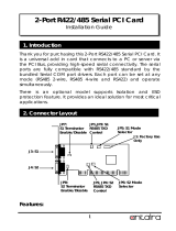
Figure 1: CP347 Functional Block Diagram

CP347 – User Guide, Rev. 1.3
www.kontron.com // 12
Front Panel 1.2.1.
Figure 2: CP347 Front Panel
1. Front Panel LEDs
Eight indicator LEDs monitor the operation of the four serial channels.
Two LEDs for each of the four channels:
4x yellow LEDs for Rx
4x green LEDs for Tx
2. Front Panel Serial I/O Connector
A 37-pin D-Sub connector is accessible on the front panel and contains signals
for four RS232 or RS 422/RS485 serial interfaces, controlled and converted by
a PCI to serial controller. For the 37-pin D-Sub connector’s pin assignment, see
Chapter 2.3.1 Front Panel Serial I/O Connector.
1.2.1.1. Front Panel Adapter
A front panel adapter cable (CP-ADAP-CP346-CP347) can be connected to the 37-pin D-Sub front panel connector to
provide discrete access to the separate serial I/O channels. This adapter cable terminates on the user side with four
male 9-pin D-Sub connectors, one per serial I/O channel. For more information see, Chapter 4.4.1 Four-Channel Front
Panel Adapter cable.
1
2

CP347 – User Guide, Rev. 1.3
www.kontron.com // 13
Board Layout 1.2.2.
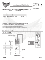
Figure 3: CP347 Board Layout (Top View)
Connector and Component Description
Item Connector Description Chapter
1 Con2 37-pin D-Sub front panel connector
2.3.1
6 Con3 12-pin JTAG/ISP connector
2.3.3
14 Con1 CompactPCI connector J1 in the CompactPCI specification
2.3.4
Item Configurable
Components
Description Chapter
2 R16, R17, R18, R19,
R20, R21, R22, R23
8x 0 Ω resistors configure the channel’s operation mode as an
alternative to SW1 (Listed from left to right)
3.1.1
3 D1 8x front panel LEDs
1.2.1
4 SW1 Eight-port DIP switch
3.1.1
1
4
7
3
23
17
13
10
8
15
16
14
5 6
9
2
20
19
22
21
18
11
12

CP347 – User Guide, Rev. 1.3
www.kontron.com // 14
Item Configurable
Components
Description Chapter
5 R44, R45
2x 0 Ω resistors to configure CPLD RTS# or DTR# inputs for channel 1
(Listed from left to right)
3.1.3
8 R32, R33
2x 0 Ω resistors to configure CPLD RTS# or DTR# inputs for channel 0
(Listed from left to right)
3.1.3
10 R37, R38,
2x 0 Ω resistors to configure CPLD RTS# or DTR# inputs for channel 3
(Listed from left to right)
3.1.3
11 R46, R47
2x 0 Ω resistors to configure CPLD RTS# or DTR# inputs for channel 2
(Listed from left to right)
3.1.3
23 JP1, JP2, JP3, JP4,
JP5, JP6, JP7, JP8
Bus termination solder-jumpers (Listed from top to bottom) 3.1.2
Item Components Description
7 U7 CPLD
9 U11 Voltage translator
12 U3, U4, U8, U12,
U16, U20, U22, U25
Digital isolation
(Listed from top right to bottom right)
13 U5, U6 LED buffer to activate Tx and Rx front panel LEDs
15 U17 PCI controller with four UART interfaces, Exar XR17D154
16 U21 Position of an optional EEPROM
17 Y1 Clock supply
18 U15 Voltage isolation
19 U9, U10 Channel 3 RSxxx transceiver
( Listed from left to right)
20 U13, U14 Channel 2 RSxxx transceiver
( Listed from left to right)
21 U18, U19 Channel 1 RSxxx transceiver
( Listed from left to right)
22 U23, U24 Channel 0 RSxxx transceiver
( Listed from left to right)

CP347 – User Guide, Rev. 1.3
www.kontron.com // 15
1.3. Technical Specification
Table 1: CP347 Technical Specifications
Form Factor
Form Factor 3U/4HP CompactPCI board
Dimensions and Weight 100 mm x 160 mm (3U card size) and 142 gram
3,94” x 6.3” single height and 0.31 pounds
Controller
CompactPCI to Serial Interface Exar XR17D154, internal CompactPCI port to external serial interface bridge
CPLD Altera Max V 5M40ZE64I5N, switches the RS232, RS422/RS485 transceivers
On/Off, as defined in the user configuration
System Interconnection
Serial I/O interface RS232, RS422 full duplex and RS485 half duplex
Serial I/O Channels 4x channels, individually configurable via hardware and software
Serial Data Rates Up to 115.2 kbps
Programmable Data Formats Up to 64-byte transmit and receive FIFOs
Automatic RTS/CTS or DTR/DSR flow control
Automatic Xon/Xoff software flow control
Automatic RS485 half duplex control output
Configurable Channel Modes RS232
RS422 full duplex (4-wire)
RS485 with local echo half duplex (2-wire)
RS485 without local echo half duplex (2-wire)
Front Panel
External Board Interfaces 1x 37-pin D-Sub
LEDs Eight operation indicator LEDs (two for each channel):
4x yellow Rx
4x green Tx
Power Considerations
Power Supply 5 V DC
Isolation Voltage 2 kV between CompactPCI system and D-Sub front panel
Overvoltage Protection RSxxx transceiver I/Os can handle ±12 V
PCI Interface 5 V or 3.3 V (I/O) PCI Bus connection
Power Consumption 2 Watt (Typical)
Software
Operating systems Drivers are supplied for the operating systems:
Windows®
Linux®
VxWorks®

CP347 – User Guide, Rev. 1.3
www.kontron.com // 16
1.4. Environmental Considerations
Table 2: Environmental Specification
Environmental Specification
Operating Temperature
Standard range
0°C to +70°C
In a passive cooled system, the maximum ambient
temperature is +48°C.
Operating Temperature
Extended range
-40°C to +85°C
In a passive cooled system, the maximum ambient
temperature is +63 °C.
Storage Temperature
-55 °C to +125 °C
Humidity 93 % RH non-condensing
Operating Altitude Up to 2000 m
The difference between ambient temperature and the temperature inside the system must
be considered.
Forced air-cooling is required and must be considered in the system.
If the system is operated in a dust-prone environment, an air filter must be considered for
dust protection.

CP347 – User Guide, Rev. 1.3
www.kontron.com // 17
1.5. Standards
Table 3: Applied Standards:
Standard Type Description
Emission EN 55022 Radiated emission Information technology equipment, radio
disturbance characteristics- limits and
methods of measurement
EN 61000-6-3 EMC emmission Generic Emission standard, part 3
residential, commercial and light industry
Immunity
EN 61000-6-2 EMC immunity Generic standards, immunity for industrial
environment
EN 55024 Information technology equipment immunity
characteristics limits and methods of
measurement
EN 61000-4-2 Electrostatic Discharge
EN 61000-4-3 RF electromagnetic fields
EN 61000-4-4 Burst
EN 61000-4-5 Surge
EN 61000-4-6 Conducted interferences
Safety
EN 60950-1
UL/CSA 60950-1
Electrical safety IT-equipment
EN 62368-1 Electrical safety Safety for audio/video and information
technology equipment
Vibration
IEC 60068-2-6 Vibration Sinusoidal, 10 Hz – 300 Hz, 5 g
IEC 60068-2-64 Random vibration 20 Hz – 500 Hz or 500 Hz to 2000 Hz, 3.6 g
Bump IEC 60068-2-29 Bump Half sine. 11 ms, 15 g
Shock IEC 60068-2-27 Single shock Half sine. 9 ms, 30 g
Environmantal
IEC 60068-2-78 Humidity
IEC 60068-2-1 Thermal operation
IEC 60068-2-2
Environmental Rohs II Restriction of Hazardous
Substances
Restriction of use of hazardous substances in
electrical and electronic equipment

CP347 – User Guide, Rev. 1.3
www.kontron.com // 18
1.6. Power Requirements
The CP347’s supply voltage is 5 V DC. An on-board 5 V/5 V, DC/DC voltage isolator, isolates the serial channels from
the CompactPCI interface.
The CP347 provides a universal CompactPCI interface and can work properly with 5 V and
3.3 V PCI V (I/O) signaling.
1.7. Related Publications
Table 4: Related Publications
Product Publication
CompactPCI systems and boards CompactPCI Specification 2.0, Rev. 3.0
Kontron CompactPCI System Manual, ID 19954

CP347 – User Guide, Rev. 1.3
www.kontron.com // 19
2/ Functional Description
2.1. General Information
The CP347 serial communications controller board is the realization of a low cost solution for industrial automation
communication purposes and represents the implementation of a serial communication controller board at the basic
OSI levels.
The main functions implemented on the CP347 board are the OSI Layer 2 data link control for RS232, RS422 and
RS485 communication purposes, and the OSI Layer 1 physical signal level adaptation for the RS232, RS422 and RS485
interfaces. The RS422 interface is realized for full duplex (4-wire) and the RS485 Interface is realized for half duplex
(2-wire) operation.
The physical layer adaptation (OSI Layer 1) of the TTL interface signals is realized independently for each channel via
corresponding on-board RS232, RS422/RS485 transceivers. Each of the four serial communication links are
configured individually for serial interface operation per hardware and software, including the serial line termination
for balanced serial communication.
2.2. Specifics
The OSI Layer 2 functions for serial communication are handled entirely by the Exar XR17D154 serial I/O controller.
This controller handles all the on-board serial communication tasks related to the OSI Layer 2, and also the data
transfer to the system host CPU over the CompactPCI bus.
For the various operation types, configuration of the serial communication links as well as serial line termination for
differential communication (RS422/RS485) is accomplished via hardware and software. The four serial I/O channels
are independent and can be configured individually for RS232, RS422/RS485 serial communication.
The data transfer operation of the serial channels is indicated at the front panel by four channel related pairs of LEDs,
for receive and transmit operations.
The communication functions including the RS232, RS422 and RS485 serial I/O functions are tied to the host system
via the standard PCI interface provided directly on the Exar XR17D154. Logical control of the CP347 serial
communication operation is accomplished via the Exar XR17D154 command and status registers that can be accessed
independently for each channel directly from the PCI side.
The CP347 serial I/O board is provided with a 37-pin D-Sub connector providing the signals for all four serial I/O
channels. In order to provide separate serial I/O channeling, a front panel adapter can be connected to the 37-pin
front panel connector. This adapter terminates on the user side with four, male, 9-pin, D-Sub connectors (one per
serial I/O channel).
In addition, the CP347 is galvanic isolated between the system side and the serial I/O front panel D-Sub connector for
all four channels. This is accomplished with digital isolators using the iCoupler® technology. This is especially useful
in industrial environments, where voltage potential differences between the different transmission stations can
occur. Using this technology GND compensating currents can be avoided or minimized and the digital system side,
where expensive components such as CPU are located, is protected against noise transients.
An optional 1 Kbit EEPROM can be assembled to store the vendor’s ID and model number, and the sub-vendor’s ID and
product model number. If an EEPROM is assembled, the PCI controller reads four word data from the EEPROM’s first
four word locations and places those values into the PCI configuration space registers for chipset identification.
Additionally, the EEPROM can store proprietary data. If no EEPROM is assembled, the PCI controller uses the default
value of the PCI controller’s vendor and device ID. The IDs are stored in the configuration space for chipset
identification during the auto-configuration sequence.
2.3. Board Interfaces
The CP347 serial I/O board provides a 37-pin D-Sub connector with signals for all four serial I/O channels.
Additionally, in order to provide separate serial I/O channeling, it is possible to connect a front panel adapter to the
37-pin D-Sub front panel connector. This adapter terminates on the user side with four male 9-pin D-Sub connectors,

CP347 – User Guide, Rev. 1.3
www.kontron.com // 20
one per serial I/O channel. This chapter includes pin assignment information for both the 37-pin D-Sub front panel
connector and the four-channel front panel adapter cable’s 9-pin D-Sub connectors.
Front Panel Serial I/O Connector 2.3.1.
The front panel serial I/O, 37-pin D-Sub dual row, connector comprises of the signals for channels 0 to 3.
Do not connect external wiring to the connector pins if signals are not indicated in the table
below or are marked with NC. Failure to comply may result in damage to your board.
Table 5: 37-Pin D-Sub Front Panel Connector Pin Assignment
Channel Signal
Front Panel
Pin # RS232
Direction
RS232 RS485
Half Duplex
RS422
Full Duplex
Front Panel
37-Pin D-Sub Connector
0 FE01 37 In DCD RxD+
FE02 36 In RXD#
FE03 35 Out TXD# TRxD+ TxD+
FE04 34 Out DTR
FE06 18 In DSR RxD-
FE07 17 Out RTS
FE08 16 In CTS TRxD- TxD-
FE09 15 In RI
1 FE11 10 In DCD RxD+
FE12 11 In RXD#
FE13 12 Out TXD# TRxD+ TxD+
FE14 13 Out DTR
FE16 29 In DSR RxD-
FE17 30 Out RTS
FE18 31 In CTS TRxD- TxD-
FE19 32 In RI
2 FE21 28 In DCD RxD+
FE22 27 In RXD#
FE23 26 Out TXD# TRxD+ TxD+
FE24 25 Out DTR
FE26 9 In DSR RxD-
FE27 8 Out RTS
FE28 7 In CTS TRxD- TxD-
FE29 6 In RI
3 FE31 1 In DCD RxD+
FE32
2
In RXD#
FE33 3 Out TXD# TRxD+ TxD+
FE34 4 Out DTR
FE36 20 In DSR RxD-
FE37 21 Out RTS
FE38 22 In CTS TRxD- TxD-
FE39 23 In RI
GND_DSUB 5 GND GND GND
GND_DSUB 14 GND GND GND
GND_DSUB 24 GND GND GND
GND_DSUB 33 GND GND GND
NC 19 NC NC NC NC
S1 Shield
S2 Shield
/