
SM07251 Windmill Assembly 1
READ ALL INSTRUCTIONS AND WARNINGS BEFORE USING THIS PRODUCT.
This manual provides important information on proper operation & maintenance. Every effort has been
made to ensure the accuracy of this manual. These instructions are not meant to cover every possible
condition and situation that may occur. We reserve the right to change this product at any time without
prior notice.
IF THERE IS ANY QUESTION ABOUT A CONDITION BEING SAFE OR UNSAFE,
DO NOT OPERATE THIS PRODUCT!
DO NOT RETURN THIS PRODUCT TO THE RETAILER - CONTACT CUSTOMER SERVICE.
If you experience a problem, have questions or need parts for this product, call Customer Service at
1-888-287-6981, Monday-Friday, 8 AM - 4 PM Central Time. A copy of the sales receipt is required.
FOR CONSUMER USE ONLY – NOT FOR PROFESSIONAL USE.
KEEP THIS MANUAL, SALES RECEIPT & APPLICABLE WARRANTY FOR FUTURE
REFERENCE.
SM07251
Windmill
Assembly
Instructions
PLEASE CAREFULLY REVIEW EACH PARTS COMPONENT BELOW BEFORE
ASSEMBLY. ASSEMBLY TIME MAY TAKE SEVERAL HOURS.

SM07251 Windmill Assembly 2
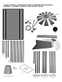
PLEASE CAREFULLY REVIEW EACH PARTS COMPONENT BELOW BEFORE
ASSEMBLY. ASSEMBLY TIME MAY TAKE SEVERAL HOURS.
Part
Description
Qty.
A
Mast Head
1
B
Mast Head Washer
1
C
Square Platform
1
D
Center Wheel
1
E
Center Wheel Cap
1
F
Fan Blade Bolt (M4 x 8)
39
G
Fan Blade Self-Locking Nut
36
H
Fan Blades
12
I
Tail
1
J
Tail Support Bar
2
K
Wheel Arm
1
L
Brace Screw (M5 x12)
33
M
Brace Nut (M5)
33
N
Cotter Pin
2
O
Middle Brace (12.5) Inches)
4
P
Bottom Brace (19.5) Inches)
4
Q
Cross Brace (29.5) Inches)
16
R
Top Legs (28 Inches)
4
S
Center Legs (28 inches)
4
T
Bottom Legs (27.5 Inches)
4
U
Ground Stake
4
I
J
K
U
D
H
B
L
M
N
F
G
E
Mast
Head (A)
T
S
R
C
O
Q
P

SM07251 Windmill Assembly 3
KEEP AWAY FROM ELECTRICAL POWER LINES. KEEP OUT OF REACH OF CHILDREN. THIS IS
NOT A TOY. DO NOT CLIMB ON THE WINDMILL.
ASSEMBLY
One person can complete the windmill assembly in several hours, but having a second person will make the process easier and
save a little time. Read all instructions carefully and completely before beginning. Refer to the Parts List and check that all pieces have
been included before beginning assembly.
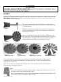
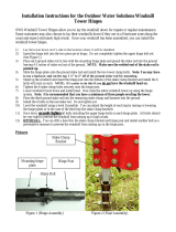
Connect the tail assembly by placing the Tail Support Bars (J) on either side of the
Tail (I). Align the pre-drilled holes on all three pieces, and connect with two Brace Bolts
(L) and Brace Nuts (M).
Slide the fin of the Wheel Arm (K) between the open ends of the Tail Support Bars (J)
and align the pre-drilled holes on all three pieces. Connect with three Brace Bolts (L)
and Brace Nuts (M). (Figure 1)
Attach the Fan Blades (H) to the Center Wheel (D) with the Fan Blade Bolts (F) and
Self-Locking Nuts (G). Each Fan Blade (H) will use three bolts and nuts. The side of the
Fan Blades (H) with the black edge should face to the front, and the Fan Blade (H)
should be attached behind the blade on the Center Wheel (P). (Figure 2 )
Fasten the four Top Legs (R) on the outside of the Mast Head (A), by aligning the pre-drilled holes in each piece and
securing with a Brace Screw (L) and Brace Nut (M). (Figure 7)
(NOTE: If you would prefer the Top Legs (R) to fit inside the Mast Head (A), additional holes may be drilled in the Top
Legs (R) to allow a snug fit.) Do not tighten the nuts at this stage.
Figure 1
Figure 2
Figure 3
Center Wheel Front
Figure 4
Center Wheel Back
Figure 5
Center Wheel & Cap Front
Connect the Center Wheel Cap (E) to the front of the Center Wheel (D) using three Fan Blade Bolts (F), (the short, wide lip
surrounding the hole in the center of the Center Wheel (D) will identify the front side. The back of the Center Wheel (D) has
a thinner, taller lip. (Figures 3 & 4)
NOTE: The screw holes in the Center Wheel (D) are threaded, and no nuts are provided to secure the elements together on
the backside of the Center Wheel (D). (Figure 5)
Figure 7
Center Wheel Front With
12 Fan Blades Attached

SM07251 Windmill Assembly 4
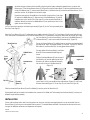
Assemble the legs and braces of the windmill by beginning at the bottom and working toward the top. Locate the four
Bottom Legs (T) and the four Bottom Braces (P). Align each end of the Bottom Brace (P) with the predrilled holes on the
inside of the Bottom Legs (T), and secure with Brace Bolts (L) and Brace Nuts (M) so that the four Bottom Braces (P) are
parallel to the floor. Do not tighten the nuts at this stage.
Repeat the same steps for the middle tier of the windmill. Locate the four Center Legs
(R) and the four Middle Braces (O). Align each end of the Middle Braces (O) with the
predrilled holes on the inside of the Center Legs (R), and secure with Brace Bolts (L)
and Brace Nuts (M) so that the four Middle Braces (O) are parallel to the floor. Do not
tighten the nuts at this stage.
Join the Center Leg assembly to the Bottom Leg assembly (Figure 8). Join the Top Leg assembly to the
top of the Center Legs (S).
Attach the Cross Braces (Q) in an “X” configuration in the middle and top tier (Figure 9). The Cross Braces (Q) will connect with the Legs
in the same spots as the Middle Braces (O) and the Bottom Braces (P). You will need to unscrew the Brace Nuts (M) at these joints, slide
the Cross Braces (Q) over the Brace Bolts (L) and on top of the Middle Braces (O)
or Bottom Braces (P), and re-secure with the Brace Nuts (M), (Figure 10)
Secure the Square Platform (C) by sliding it over the top of the assembled windmill
legs and braces. Attach the Square Platform (C) to the four Top Legs (R), with four
Brace Bolts (L) and Brace Nuts (M). Securely tighten Bolts and Nuts.
Securely tighten all the Brace Bolts (L) and Brace
Nuts (M) on the assembled windmill legs and
braces.
Slide the Mast Head Washer (B) onto the post of
the Wheel Arm (K) and the guide the post of the
Wheel Arm (K) and the complete tail assembly
into the hole on the top of the Mast Head (A).
(Figure 11)
Insert Cotter Pins (N) to secure Wheel Arm to Mast Head (Figure 12), and Center
Wheel to Mast Head (Figure 13). Screw Cap (E) over Cotter Pin (Figure 14).
Slide the assembled Center Wheel (D) and Fan Blades (H) onto the post of the Wheel Arm (K).
If the windmill needs to be moved to the installation site, remove the Fan Blade and Tail Assembly from the Mast Head (A), and carry the
Windmill Leg Assembly separately.
INSTALLATION
Choose a flat and level surface that is free from power lines, branches, and other overhanging objects to set up the windmill. Use the
Ground Stakes (U) to firmly secure the windmill into the ground. The windmill blades will rotate in the wind as the direction of the wind
changes. No additional maintenance or adjustments are required.
(201308)
Figure 10
Figure 11
Bottom Brace
(P)
Middle Brace
(O)
Cross
Brace
(Q)
Mast Head (A)
Figure 8
Figure
12
Figure
13
Figure
14
Ground
Stake (U)
-
 1
1
-
 2
2
-
 3
3
-
 4
4


Sportsman Series SM07251 User manual
- Type
- User manual
- This manual is also suitable for
Ask a question and I''ll find the answer in the document
Finding information in a document is now easier with AI
Other documents
-
 Outdoor Water Solutions PSP0149 Installation guide
-
 Outdoor Water Solutions AWS0179 Operating instructions
-
 Outdoor Water Solutions WTW0114 Installation guide
-
 Outdoor Water Solutions WNP0041 Owner's manual
-
PASCO ME-7003 Owner's manual
-
Sunnydaze Decor KF-3MTS-MC Operating instructions
-
-
 Strongway Ornamental Garden Windmill Owner's manual
-
Leigh Country TX 93480 User guide
-
SIG SIGRC90 User manual


