
ViPR
Wireless Radio Modem
User Manual
Preliminary – For Internal Use Only
Copyright DATARADIO Inc.
April 2007
Part no.:

120 40520-100a ViPR User Manual
ii
Table of Contents
1. PRODUCT OVERVIEW...............................................................................................................................11
1.1 INTENDED AUDIENCE....................................................................................................................................11
1.2 GENERAL DESCRIPTION.................................................................................................................................11
1.2.1 Characteristics.....................................................................................................................................12
1.2.2 Configuration.......................................................................................................................................12
1.2.3 Accessories and Options......................................................................................................................13
1.3 FACTORY TECHNICAL SUPPORT ....................................................................................................................13
1.4 PRODUCT WARRANTY, RMA AND CONTACT INFORMATION ........................................................................13
1.4.1 RMA REQUEST...................................................................................................................................13
1.4.2 PRODUCT DOCUMENTATION ........................................................................................................14
1.5 UNPACKING...................................................................................................................................................14
2. INSTALLATION............................................................................................................................................15
2.1 UL APPROVED FOR CLASS I, DIVISION 2 OR ZONE 2.....................................................................................15
2.2 ANTENNA INSTALLATION..............................................................................................................................15
2.2.1 Professional Installation & RF Exposure Compliance Requirements.................................................15
2.2.2 Antenna Connection ............................................................................................................................15
2.2.3 RF Path and communications range ...................................................................................................16
2.2.4 Antennas ..............................................................................................................................................16
2.3 NETWORK APPLICATION................................................................................................................................16
2.3.1 Modes ..................................................................................................................................................16
2.3.1.1 Bridge mode.................................................................................................................................................16
2.3.1.2 Router mode.................................................................................................................................................16
2.3.2 Connections.........................................................................................................................................16
2.4 SELECTABLE DATA RATES............................................................................................................................17
2.5 POINT TO POINT SYSTEM...............................................................................................................................18
3. PHYSICAL DESCRIPTION.........................................................................................................................19
3.1 LEDS............................................................................................................................................................20
3.2 USER CONNECTOR PIN-OUTS.........................................................................................................................21
3.2.1 Ethernet LAN Port...............................................................................................................................21
3.2.2 SETUP & COM Ports..........................................................................................................................21
3.3 DIAGNOSTIC CONNECTIONS ..........................................................................................................................23
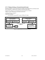
3.3.1 Parameter............................................................................................................................................23
3.3.2 Output Format.....................................................................................................................................23
3.3.2.1 Output Samples............................................................................................................................................25
4. OPERATION & CONFIGURATION..........................................................................................................26
4.1 BROWSER-BASED SETUP AND STATUS..........................................................................................................26
4.2 LAN SETUP...................................................................................................................................................26
4.3 LOGIN SCREEN ..............................................................................................................................................26
4.3.1 Initial Installation Login......................................................................................................................26
4.4 INTERFACE ....................................................................................................................................................27
4.4.1 Apply, Cancel, Save Config, and Reset Unit........................................................................................27
4.5 SETUP WIZARD (BRIDGE MODE)...................................................................................................................29
4.5.1 Procedure ............................................................................................................................................29
4.6 DEFAULT IP SETTINGS ..................................................................................................................................32
4.6.1 Ethernet Interface................................................................................................................................32
4.6.2 RF Interface.........................................................................................................................................32
4.7 IP NETWORK SETTINGS.................................................................................................................................32
4.7.1 Factory Settings in Bridge Mode.........................................................................................................32
4.7.2 IP Network Settings in Bridge Mode ...................................................................................................33
4.7.3 IP Network Settings in Router Mode (with Host) ................................................................................33
4.7.4 IP Network Settings in Router Mode (with Router).............................................................................34
4.8 ADVANCED IP SETTINGS...............................................................................................................................35

120 40520-100a ViPR User Manual
iii
4.8.1 Unit Status ...........................................................................................................................................35
4.8.2 Setup (Basic)........................................................................................................................................36
4.8.2.1 Setup (General)............................................................................................................................................36
4.8.2.2 Basic IP Configuration.................................................................................................................................37
4.8.2.3 RF Setup ......................................................................................................................................................38
4.8.2.4 Serial Ports Setup.........................................................................................................................................39
4.8.2.5 Diagnostics...................................................................................................................................................41
4.8.3 Setup (Advanced).................................................................................................................................42
4.8.3.1 LAN (IP)......................................................................................................................................................42
4.8.3.2 RF (IP).........................................................................................................................................................43
4.8.3.3 IP Services Setup.........................................................................................................................................44
4.8.3.3.1 NAT Overview........................................................................................................................................45
4.8.3.4 IP addressing modes ....................................................................................................................................47
4.8.3.4.1 IP Broadcast/Multicast Overview ...........................................................................................................48
4.8.3.5 IP Optimization & Tuning ...........................................................................................................................52
4.8.3.6 Time Source.................................................................................................................................................53
4.8.3.7 Ethernet (PHY)............................................................................................................................................54
4.8.3.8 RF Link........................................................................................................................................................54
4.8.4 Security................................................................................................................................................55
4.8.4.1 Pass Control.................................................................................................................................................55
4.8.4.2 Access List...................................................................................................................................................56
4.8.5 Statistics...............................................................................................................................................57
4.8.5.1 TCP/IP .........................................................................................................................................................57
4.8.5.2 AirLink ........................................................................................................................................................58
4.8.5.3 Interfaces......................................................................................................................................................58
4.8.6 Maintenance ........................................................................................................................................59
4.8.6.1 Ping Test......................................................................................................................................................59
4.8.6.2 Unit Configuration Control..........................................................................................................................60
4.8.6.3 Package Control...........................................................................................................................................61
4.8.7 Radio - RF Tests..................................................................................................................................62
4.8.8 Help .....................................................................................................................................................62
5. OPTIMIZATION & TROUBLESHOOTING.............................................................................................63
5.1 MAXIMIZING TCP/IP.....................................................................................................................................65
5.2 MAXIMIZING VIA SETUP PAGES.....................................................................................................................65
5.2.1 Use Router Mode.................................................................................................................................65
5.2.2 Reduce RF MTU size............................................................................. Error! Bookmark not defined.
5.2.3 Reduce RF network bit rate.................................................................................................................65
5.2.4 Increase OIP Retries Limit..................................................................................................................65
5.3 TROUBLESHOOTING TOOLS ...........................................................................................................................66
5.3.1 Network Connectivity...........................................................................................................................66
5.3.2 Configuration Information ..................................................................................................................67
5.3.3 Statistics Information...........................................................................................................................67
5.4 FIRMWARE UPGRADING ................................................................................................................................68
5.4.1 Procedure ............................................................................................................................................68
5.4.1.1 File Integrity Failure....................................................................................................................................69
6. SPECIFICATIONS ........................................................................................................................................70
FIGURE 1 – VIPR – TO BE UPDATED WHEN AVAILABLE..............................................................................................11
FIGURE 3 – ANTENNA ................................................................................................................................................16
FIGURE 4 - BASIC SETUP ............................................................................................................................................17
FIGURE 5 - SETUP USING SWITCH (OR HUB) AND POE POWER INJECTOR....................................................................17
FIGURE 6 - POINT-TO-POINT IP NETWORK SYSTEM...................................................................................................18
FIGURE 7 - POINT-TO-MULTIPOINT SYSTEM...............................................................................................................18
FIGURE 8 - VIPR FRONT PANEL.................................................................................................................................19
FIGURE 9 - PACKETS COUNTS FOR PER .....................................................................................................................24

120 40520-100a ViPR User Manual
iv
FIGURE 10 - ENTER NETWORK PASSWORD SCREEN (APPEARANCE MAY VARY WITH BROWSER USED) .......................26
FIGURE 11 - WEB USER INTERFACE – WELCOME SCREEN .........................................................................................27
FIGURE 13 – ATTENTION SUB-WINDOW......................................................................................................................27
FIGURE 14 - SETUP WIZARD - PAGE ONE...................................................................................................................29
FIGURE 15 - SETUP WIZARD - PAGE TWO ..................................................................................................................29
FIGURE 16 - SETUP WIZARD - PAGE THREE ...............................................................................................................30
FIGURE 17 - SETUP WIZARD - PAGE FOUR.................................................................................................................30
FIGURE 18 - SETUP WIZARD - PAGE FIVE (ROUTER MODE)........................................................................................31
FIGURE 19 - SETUP WIZARD – PAGE FIVE (BRIDGE MODE)........................................................................................31
FIGURE 20 - FACTORY IP NETWORK SETTINGS IN TRANSPARENT BRIDGE MODE WITH NO SERVICES ........................32
FIGURE 21 - IP NETWORK SETTINGS IN TRANSPARENT BRIDGE MODE WITH SERVICES..............................................33
FIGURE 22 - IP NETWORK SETTINGS IN ROUTER MODE (WITH HOST)........................................................................33
FIGURE 23 - IP NETWORK SETTINGS IN ROUTER MODE (WITH ROUTER) ...................................................................34
FIGURE 24 - UNIT STATUS..........................................................................................................................................35
FIGURE 25 – SETUP (BASIC) GENERAL ......................................................................................................................36
FIGURE 26 - SETUP (BASIC) – BASIC IP CONFIGURATION..........................................................................................37
FIGURE 27 - SETUP (BASIC) – RF SETUP...................................................................................................................38
FIGURE 28 - SETUP (BASIC) – RF SETUP....................................................................................................................39
FIGURE 29 - DIAGNOSTICS – THINNING VALUE..........................................................................................................41
FIGURE 30 - ADVANCED IP CONFIGURATION - LAN (IP)..........................................................................................42
FIGURE 31 - ADVANCED IP CONFIGURATION - RF (IP)..............................................................................................43
FIGURE 32 - ADVANCED IP CONFIGURATION – IP SERVICES SETUP..........................................................................44
FIGURE 33 - BASIC NAT OPERATIONS.......................................................................................................................45
FIGURE 34 - NAT ENABLED ON VIPR........................................................................................................................46
FIGURE 35 - PRIVATE TO PUBLIC................................................................................................................................46
FIGURE 36 - ADVANCED IP CONFIGURATION – IP ADRESSING MODES.......................................................................47
FIGURE 37 - REGISTRATION TO MULTICAST GROUP (FIRST STEP) ...............................................................................48
FIGURE 38 - RECEPTION OF MULTICAST PACKETS (SECOND STEP)..............................................................................49
FIGURE 39 - BROADCAST WINDOW DETAIL...............................................................................................................49
FIGURE 40 - TYPICAL VIPR MULTICAST GROUPS......................................................................................................50
FIGURE 41 - MULTICAST WINDOW DETAILS (ON THE MAIN VIPR UNIT)...................................................................51
FIGURE 42 - REGISTRATION TO MULTICAST GROUP....................................................................................................51
FIGURE 43 - ADVANCED IP CONFIGURATION – IP OPTIMIZATION & TUNING (ROUTER MODE)................................52
FIGURE 44 - ADVANCED IP CONFIGURATION – TIME SOURCE...................................................................................53
FIGURE 45 - ADVANCED IP CONFIGURATION – ETHERNET (PHY).............................................................................54
FIGURE 46 - ADVANCED IP CONFIGURATION – RF LINK...........................................................................................54
FIGURE 47 - SECURITY – PASS CONTROL...................................................................................................................55
FIGURE 48 - SECURITY – ACCESS LIST.......................................................................................................................56
FIGURE 49 - STATISTICS – TCP/IP.............................................................................................................................57
FIGURE 50 - STATISTICS – AIRLINK – CHANNEL UTILIZATION...................................................................................58
FIGURE 51 - STATISTICS – INTERFACES......................................................................................................................58
FIGURE 52 - MAINTENANCE – PING TEST...................................................................................................................59
FIGURE 53 - MAINTENANCE - UNIT CONFIGURATION CONTROL (INITIAL SCREEN)....................................................60
FIGURE 54 – PACKAGE CONTROL...............................................................................................................................61
FIGURE 55 - RF TESTS ...............................................................................................................................................62
FIGURE 56 - HELP ICON..............................................................................................................................................62
FIGURE 57 - SAMPLE FTP PROGRAM .........................................................................................................................69
TABLE 1 – ON-AIR DATA RATES, BIT AND BAUD RATES ...........................................................................................12
TABLE 2 - ACCESSORIES ............................................................................................................................................13
TABLE 3 - VIPR LEDS INDICATIONS ..........................................................................................................................20
TABLE 4 - PIN-OUT FOR IEEE-802.3AF RJ-45 RECEPTACLE CONTACTS .....................................................................21
TABLE 5 - PIN-OUT FOR DCE J11A & B, 9-CONTACT DE-9 CONNECTOR..................................................................21
TABLE 6 - SIMPLIFIED RATING OF OUTPUT VALUE REPRESENTING PACKET ERROR RATE (PER)................................24

120 40520-100a ViPR User Manual
v
TABLE 7 – DECODING SAMPLE OUTPUT FOR ROUTER MODE.....................................................................................25
APPENDIX 1 - DATA TELEMETRY WARRANTY ...........................................................................................................72

120 40520-100a ViPR User Manual
vi
What's New in this version
History
Version 1.00, Preliminary, 12December 2006
• Draft leading to Initial release of Dataradio® ViPR™ wireless ra-
dio modem User Manual
Version 2.00, Preliminary, 11 April 2007
• Changed iPR radio name to ViPR. Made numerous updates to speci-
fications. Removed references to HiPR-900.

120 40520-100a ViPR User Manual
vii
About Dataradio
Dataradio is a leading designer and manufacturer of advanced wireless data products and systems for mis-
sion critical applications. Our products are found at the heart of mobile data and SCADA networks
around the world.
With over 25 years dedicated to data technology and innovation, Dataradio is the premier source for wire-
less data solutions. Our products include mobile data products, telemetry devices, integrated wireless mo-
dems for fixed point-to-point and point to multi-point applications, and OEMs. Our product line is one of
the broadest in the industry covering the most often-used frequency bands.
Dataradio COR Ltd.
Dataradio COR Ltd. designs and manufactures radios and integrated wireless modems to serve a wide
variety of data communication needs. Dataradio produces equipment for the fixed data market including
SCADA systems for utilities, petrochemical, waste and fresh water management markets and RF boards
for OEM applications in the Radio Frequency Data Capture market.
Product Warranty
The manufacturer's warranty statement for this product is available in Appendix 1.
www.dataradio.com
Dataradio provides product brochures, case studies, software downloads, and product information on our
website. Every effort is taken to provide accurate, timely product information in this user manual.
Product updates may result in differences between the information provided herein and the product
shipped. The information in this document is subject to change without notice.
DATARADIO is a registered trademark, ViPR and TRUSTED WIRELESS DATA are trademarks of Dataradio Inc

120 40520-100a ViPR User Manual
viii
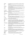
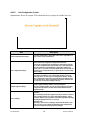
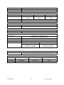
Definitions
Item Definition
Access Point Communication hub for users to connect to a LAN. Access Points are important
for providing heightened wireless security and for extending the physical range
of service a wireless user has access to.
AES Advanced Encryption Standard (AES)
Airlink Physical radio frequency connections used for communications between units.
ARP Address Resolution Protocol – Maps Internet address to physical address.
Backbone The part of a network that connects most of the systems and networks together,
and handles the most data.
Bandwidth The transmission capacity of a given device or network.
Browser An application program that provides a way to look at and interact with all the in-
formation on the World Wide Web.
Collision LED Connection is established but collisions are occurring.
COM Port Both RS-232 serial communications ports of the ViPR wireless radio modem are
configured as DCE and are designed to connect directly to a DTE.
Default Gateway A device that forwards Internet traffic from your local area network.
DCE Data Communications Equipment. This designation is applied to equipment such
as modems. DCE is designed to connect to DTE.
DHCP Dynamic Host Configuration Protocol - A networking protocol that allows ad-
ministrators to assign temporary IP addresses to network computers by "leasing"
an IP address to a user for a limited amount of time, instead of assigning perma-
nent IP addresses.
DNS Domain Name Server - translates the domain name into an IP address.
Domain A specific name for a network of computers.
DTE Data Terminal Equipment. This designation is applied to equipment such as ter-
minals, PCs, RTUs, PLCs, etc. DTE is designed to connect to DCE.
Dynamic IP Addr A temporary IP address assigned by a DHCP server.
Ethernet IEEE standard network protocol that specifies how data is placed on and re-
trieved from a common transmission medium.
Endspan PSE Power Sourcing Equipment – Equipment used to inject PoE over the unused
conductors, over the data baring conductor, or over both types of conductors of a
4-pair standard cable (E.g: CAT5).
Firewall A set of related programs located at a network gateway server that protects the
resources of a network from users from other networks.
Firmware The programming code that runs a networking device.
Fragmentation Breaking a packet into smaller units when transmitting over a network medium
that cannot support the original size of the packet.
FTP File Transfer Protocol - A protocol used to transfer files over a TCP/IP network.

120 40520-100a ViPR User Manual
ix
Gateway A device that interconnects networks with different, incompatible communica-
tions protocols.
HDX Half Duplex. Data transmission that can occur in two directions over a single
line, using separate Tx and Rx frequencies, but only one direction at a time.
HiPR-900 Frequency hopping spread spectrum wireless modem that operates in the license-
free 902-928 MHz band.
ViPR™ DSP-based narrowband Ethernet IP radio (6.25 / 12.5 / 25 kHz – UHF). Licensed
narrowband OIP radio, “companion” to the un-licensed HiPR product.
HTTP HyperText Transport Protocol - The communications protocol used to connect to
servers on the World Wide Web.
IPCONFIG A Windows 2000 and XP utility that displays the IP address for a particular net-
working device.
LNK/ACT LED Ethernet connection established – Ethernet data activity.
MAC Media Access Control - The unique address that a manufacturer assigns to each
networking device.
Midspan PSE Power Sourcing Equipment – Equipment used to inject PoE over the unused
conductors of a 4-pair standard cable (E.g.: CAT5)
MTU Maximum Transmission Unit - The largest TCP/IP packet that the hardware can
carry.
NAT Network Address Translation - NAT technology translates IP addresses of a local
area network to a different IP address for the Internet.
Network A series of computers or devices connected for the purpose of data sharing, stor-
age, and/or transmission between users.
Network speed This is the bit rate on the RF link between units.
Node A network junction or connection point, typically a computer or work station.
OIP Optimized IP – Compresses TCP and UDP headers, and filters unnecessary ac-
knowledgments. This makes the most use of the available bandwidth.
OTA Over-The-Air - Standard for the transmission and reception of application-related
information in a wireless communications system
Parallel Decode Patented technology used by HiPR products featuring dual receivers for added
data decode sensitivity in multi-path and fading environments. (United States
Patent No: 6,853,694 B1)
PHY A PHY chip (called PHYceiver) provides interface to the Ethernet transmission
medium. Its purpose is digital access of the modulated link (usually used together
with an MII-chip).
The PHY defines data rates and transmission method parameters.
Ping Packet INternet Groper - An Internet utility used to determine whether a particu-
lar IP address is online.
PLC Programmable Logic Controller. A user-provided intelligent device that can
make decisions, gather and report information, and control other devices.
Powered Device Device that is drawing power from an Ethernet cable. A powered device is com-
patible with both midspan PSE and endspan PSE; it is insensitive to polarity
PWR LED Indicates presence of DC power input.
RIPv2 Dynamic IP routing protocol based on the distance vector algorithm.
Router A networking device that connects multiple networks together.

120 40520-100a ViPR User Manual
x
RS-232 Industry–standard interface for data transfer.
RTU Remote Terminal Unit. A user-provided SCADA device used to gather informa-
tion or control other devices.
Rx/Tx LED Transmission /Reception activity
SCADA Supervisory Control And Data Acquisition. A general term referring to systems
that gather data and/or perform control operations.
SNTP Simple Network Time Protocol - Protocol for synchronizing the clocks of com-
puter systems over packet-switched, variable-latency data networks. Uses UDP
as its transport layer.
Static IP Address A fixed address assigned to a computer or device that is connected to a network.
Static Routing Forwarding data in a network via a fixed path.
Subnet Mask An Ethernet address code that determines the size of the network.
Switch A data switch that connects computing devices to host computers, allowing a
large number of devices to share a limited number of ports.
Sync Data transmitted on a wireless network that keeps the network synchronized.
TCP Transmission Control Protocol - A network protocol for transmitting data that re-
quires acknowledgement from the recipient of data sent.
TCP/IP Transmission Control Protocol/Internet Protocol - A set of protocols to commu-
nicate over a network.
TDD Time Division Duplex - Allows (virtually) simultaneous transmission in both di-
rections. The uplink and downlink transmissions use the same frequency, but are
allocated different time slots.
Telnet A user command and TCP/IP protocol used for accessing remote PCs.
TFTP Trivial File Transfer Protocol – UDP/IP based file transfer protocol.
Topology The physical layout of a network.
Transparent A transparent unit transmits all data without regard to special characters, etc.
Terminal Server Acts as a converter between Ethernet/IP and RS-232 protocols.
Tx/Rx LED Airlink data activity
UDP User Datagram Protocol - A network protocol for transmitting data that does not
require acknowledgement from the recipient of the data that is sent.
Upgrade To replace existing software or firmware with a newer version.
URL Universal Resource Locator - The address of a file located on the Internet.
VPN Virtual Private Network - A security measure to protect data as it leaves one net-
work and goes to another over the Internet.
WINIPCFG A Windows 98 and Me utility that displays the IP address for a particular net-
working device.
WLAN Wireless Local Area Network - A group of computers and associated devices that
communicate with each other wirelessly.

120 40520-100a ViPR User Manual
11
1. Product Overview
This document provides information required for the operation and verification of the DATARADIO®
ViPR narrowband Ethernet IP radiomodem.
1.1 Intended Audience
This manual is intended for system designers, professional installers, and maintenance technicians.
1.2 General Description
Dataradio’s ViPR radiomodem is a DSP-based narrowband Ethernet IP radio that operates in the UHF
(406.1-512 MHz) and VHF (136-174 MHZ) frequency ranges.
The ViPR radiomodem is designed for SCADA, telemetry, control, and industrial applications in Point-
to-Point and Point-to-Multipoint configurations.
The ViPR radiomodem supports serial and Ethernet/IP Remote Terminal Units (RTU) and programmable
logic controllers (PLC). It is standard IEEE 802.3af compliant.
The ViPR wireless modem consists of two logic PCBs; one that includes the modem circuitry and the
other the radio module. Both are installed in a cast aluminum case.
The unit is not hermetically sealed and should be mounted in a suitable enclosure when dust and/or a cor-
rosive atmosphere are anticipated. There are no external switches or adjustments; all operating parameters
are set via a web browser.
Figure 1 – ViPR – to be updated when available

120 40520-100a ViPR User Manual
12
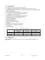
1.2.1 Characteristics
The ViPR product has the following operational characteristics:
• An ViPR RF deck, frequency range of 406.1-470 MHz, 450-512 MHz and 136-174 MHz
• High-speed user-selectable data rates of up to 32 Kbps in full channel, 16 Kbps in half channel, and 8
Kbps in quarter channel.
• Built-in transceiver adjustable to 10 watts.
• Used as an access point or an end point with each configurable in:
♦ Bridge mode – for quick setup of units on same network
♦ Router mode - for advanced networks
• Embedded web server to access status and/or setup information.
• Remote access for over-the-air system firmware upgrades.
• Wide input power range of 10 to 30 volts DC
• AES 128-bit data encryption
• Superior data compression
• Native UDP and TCP/IP support
• Optimized IP (OIP) protocol reduction
• Diagnostics
• Supports up to 32 different frequency channel pairs
• SNMP for first-level service by non IT personnel
• RF diagnostics
• Store/Forward feature
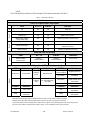
Table 1 – On-air Data Rates, Bit and Baud Rates
Quarter Channel
Channel spacing
6.25 kHz
Half Channel
Channel spacing
12.5 kHz
Full Channel
Channel Spacing
25 kHz
Bit Rates 4-8 kb/s 8 - 16 kb/s 16 – 32 kb/s
Baud Rates 4 kHz 8 kHz 16 kHz
1.2.2 Configuration
The ViPR units are factory-configured to default settings. Configuration changes or upgrades are web
browser-based.

120 40520-100a ViPR User Manual
13
1.2.3 Accessories and Options
Table 2 lists various accessory items available for the ViPR Wireless Modem.
Table 2 - Accessories
Accessory Dataradio Part Number
ViPR DIN-rail Mounting Kit 250-5099-005
(150-5099-005)
Antenna kits
7 dB 450-470 MHz Yagi Antenna Kit 250-0241-507
10 dB 450-470 MHz Yagi Antenna Kit 250-0241-510
For information on accessories and options, contact your sales representative. In the United States, call 1-800-992-7774 or 1-507-
833-8819. For International inquiries, call 507-833-8819.
1.3 Factory Technical Support
M-F 8:00 AM to 5:00 PM
Dataradio COR Ltd.
299 Johnson Ave.
Ste 110, Waseca, MN 56093
Tel 507.833.8819 Fax 507.833.6758 Email [email protected]
For application assistance, consult the Technical Support Application Notes (TSAN) at:
Dataradio.com/support.shtml
1.4 Product Warranty, RMA and Contact Information
Dataradio guarantees that every ViPR Radiomodem will be free from physical defects in material and
workmanship for two (2) years from the date of purchase when used within the limits set forth in the
Specifications section of this manual.
The manufacturer's warranty statement is available in Appendix 1. If the product proves defective during
the warranty period, contact Dataradio COR Ltd. Customer Service to obtain a Return Material Authori-
zation (RMA).
1.4.1 RMA REQUEST
Contact Customer Service:
299 Johnson Ave., Ste 110, Waseca, MN 56093
Tel 1.507.833.8819 Email [email protected]

120 40520-100a ViPR User Manual
14
BE SURE TO HAVE THE EQUIPMENT MODEL AND SERIAL NUMBER, AND BILLING AND
SHIPPING ADDRESSES ON HAND WHEN CALLING. You may also request an RMA online at
www.dataradio.com/rma.
When returning a product, mark the RMA clearly on the outside of the package. Include a complete de-
scription of the problem and the name and telephone number of a contact person. RETURN REQUESTS
WILL NOT BE PROCESSED WITHOUT THIS INFORMATION.
For units in warranty, customers are responsible for shipping charges to Dataradio. For units returned out
of warranty, customers are responsible for all shipping charges. Return shipping instructions are the re-
sponsibility of the customer.
1.4.2 PRODUCT DOCUMENTATION
Dataradio reserves the right to update its products, software, or documentation without obligation to no-
tify any individual or entity. Product updates may result in differences between the information provided
in this manual and the product shipped. For the most current product documentation, visit
www.dataradio.com for datasheets, programming software and user manuals.
1.5 Unpacking
When ready for installation, carefully unpack your ViPR radiomodem shipping carton and identify each
item as listed below:
• One ViPR radiomodem
• Power cable (5 ft) and connector
• Ethernet cable (5 ft)
• Quick Start Guide
If damage has occurred to the equipment during shipment, file a claim with the carrier immediately.

120 40520-100a ViPR User Manual
15
2. Installation
2.1 UL Approved for Class I, Division 2 or Zone 2
The ViPR radiomodem is suitable for use in Class I, Division 2, Groups A, B, A, D or non-hazardous lo-
cations. To meet UL compliance, the ViPR unit must be installed in an enclosure and power must be sup-
plied by a SELV (Safety Extra Low Voltage), non-energy hazardous source. This device is powered by a
terminal block (+).
Warning – Explosion Hazard – Do not disconnect while circuit is live unless area is know to be non-
hazardous. Substitution of components may impair suitability for Class I, Division 2 or Zone 2 operation.
2.2 Antenna Installation
2.2.1 Professional Installation & RF Exposure Compliance Requirements
The ViPR radio is intended for use in the Industrial and SCADA market. The ViPR unit must be profes-
sionally installed and must ensure a minimum separation distance between the radiating structure and any
person of more than 74 in (188 cm) for UHF (406.1-512 MHz frequencies) or more than 86 in (218 cm)
for VHF (136-174 MHz frequencies). An antenna mounted on a pole or tower is the typical installation
and in rare instances, a 1/2-wave whip antenna is used.
The ViPR radio uses a low power radio frequency transmitter. The concentrated energy from
an antenna may pose a health hazard. People should not be in front of the antenna when the
transmitter is operating.
The installer of this equipment must ensure the antenna is located or pointed such that it does not emit an
RF field in excess of Health Canada limits for the general population. Recommended safety guidelines for
the human exposure to radio frequency electromagnetic energy are contained in the Canadian Safety
Code 6 (available from Health Canada) and the Federal Communications Commission (FCC) Bulletin 65.
Notes: Any changes or modifications not expressly approved by the party responsible for com-
pliance (in the country where used) could void the user's authority to operate the equip-
ment.
2.2.2 Antenna Connection
The required antenna impedance is 50 ohms. To reduce potential radio interference, the antenna type and
its gain should be chosen to ensure the effective isotropic radiated power (EIRP) is not more than required
for successful communication.
For installation of ground-plane dependent antennas, the center of the surface used for mounting is pref-
erable for best omni-directional pattern. For ground-plane independent antennas, installation may be close
to the edges of the mounting surface.
RF Exposure

120 40520-100a ViPR User Manual
16
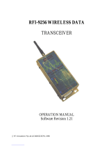
Figure 2 – Antenna
2.2.3 RF Path and communications range
The range of the ViPR radiomodem is dependent on terrain, RF (radio frequency) path obstacles, and an-
tenna system. To assure reliable communications, a competent professional should study the RF path to
determine what antennas are required and whether or not a repeater is needed.
2.2.4 Antennas
The antennas listed in Table 1, page 13 were tested and typed for maximum gain. These antennas are
FCC-approved for use with the ViPR product. Similar antenna types from other manufacturers are also
acceptable.
2.3 Network application
The ViPR radiomodem is suited to a variety of point-to-point or point-to-multipoint applications. This
section gives an overview of some common configurations.
2.3.1 Modes
2.3.1.1 Bridge mode
Bridge mode provides for fast set-up. IP bridging allows for quick deployment of basic point-to-point and
point-to-multipoint networks with minimal configuration to all units on a same network. Bridge mode
carries ARP and is transparent to any IP-based or IP-encapsulated protocols.
2.3.1.2 Router mode
Used in advanced networks, router mode enables OIP optimization for reduced overhead and improved
throughput, and supports more complex network topologies such as store-and-forward links. Only one
radio model is needed because any ViPR unit can be configured for bridge or router mode, router gateway
(access point), remote station, or even as a combined store-and-forward remote with a local drop.
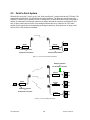
2.3.2 Connections
The connections required are shown in Figure 3 below and in Figure 4 on the next page. While serial
and/or Ethernet RTU or PLC are shown in the diagrams, master stations often use a PC running an appli-
cation designed to communicate with remote RTUs or PLCs, or intelligent controllers.

120 40520-100a ViPR User Manual
17
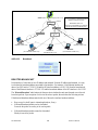
Figure 4 shows a common connection scenario. The TX/RX antenna is required for basic operation. The
power connection allows for a wide range of input DC power, whether the user system is a nominal 12 or
24 VDC supply system. A setup PC can be connected via the serial port, allowing for setup and configu-
ration of the ViPR unit as well as local and remote diagnostics. It may be left connected at all times but is
not required for normal operation once the unit has been configured. The Ethernet port allows end users
Ethernet-capable RTU or PLC to be connected.
Figure 3 - Basic Setup
Figure 5 shows the various connection opportunities for the ViPR radiomodem. The TX/RX antenna is
required for basic operation.
Figure 4 - Setup using Switch (or Hub)
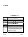
2.4 Selectable Data Rates
Switchable data rates allow optimizing installations for highest throughput or maximum range. The so-
phisticated DSP modem gives optimal performance in either mode, whether a short-range LAN extension
or long-range link.

120 40520-100a ViPR User Manual
18
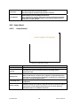
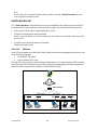
2.5 Point to Point System
Shown below are typical “point to point” and “point to multipoint” connections between ViPR units. The
connections indicated allow for either Ethernet or serial interfaces. The Ethernet connection provides
Ethernet IP connectivity for network devices. In bridge mode, all the network devices are on the same IP
Subnet. In router mode, the Ethernet connection on Master unit and the remote(s) use different IP Sub-
nets. A hub or switch may be used to allow multiple Ethernet devices to connect to the ViPR radio-
modem. Serial connections are transparent pass-through connections, allowing the use of legacy serial
devices in the ViPR product environment.
Figure 5 - Point-to-Point IP Network System
Figure 6 - Point-to-Multipoint System
ViPR RTU
Remote
PLC
Ethernet Connection
or
RS-232 Serial Connection
ViPR
Master
Host PC Ethernet Connection
or
RS-232 Serial Connection
ViPR
Master
Host PC
Ethernet Connection
or
RS-232 Serial Connection
ViPR
Remote RTU
PLC
Ethernet Connection
or
RS-232 Serial Connection
ViPR
Remote RTU
PLC
ViPR
Remote RTU
PLC

120 40520-100a ViPR User Manual
19
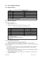
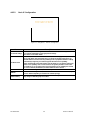
3. Physical Description
Figure 7 - ViPR Front Panel
The front panel only has connections and indicators. They are:
• One standard RJ-45 auto-sensing 10/100 UTP Ethernet connection with Auto-MDIX. Supports
direct connection to both Terminal Devices and Ethernet hubs or switches without resorting to
crossover cables. LED indicators make it simple to verify that Ethernet cables and connections
are good.
• Two DE-9F RS232 ports. Serial baud rates from 300 to 115,200 are supported. ViPR units are
factory set (default) for 115,200 b/s, 8 bits, no parity, and 1 stop bit.
• The antenna connector for the transceiver is a female 50-ohm TNC type.
• One right-angle power connector. The 10 to 30 VDC wide-range switching power supply permits
powering from 12 volt as well as 24 volt systems, and the high-efficiency switching design runs
cooler with less loss.

120 40520-100a ViPR User Manual
20
LEDS
The ViPR unit has five dual-color LED indicators. Their functions are shown in Table 3.
Table 3 - ViPR LEDs indications
ViPR LEDs indications
Power-on Sequence (LEDs are grouped)
PWR RX / TX STATUS Indication
Off
Off Off Off ViPR Off
Solid Red Off Off Boot in progress
Blinking Red on Black
(3 short red) Off Off RAM or Self Test Error
Boot 1
Blinking Red on Black
(Long / Short reds) Off Off Unable to proceed to next boot step
Solid Amber Off Off Boot in progress
Blinking Amber on Black
(Short amber blink) Off Off Exception error
(Reboot in 10 secs)
Boot 2
Blinking Red on Amber
(Short red blink) Off Off Unable to complete boot process
Power ON (LEDs are grouped)
PWR RX / TX STATUS Indication
Blinking
Amber on Black
(1/2 sec each)
Blinking
Amber on Black
Blinking
Amber on Black Service mode
Special
Solid Amber Solid Amber Solid Amber Test jumpers installed
Normal Operation (LEDs are independent)
PWR Indication RX / TX Indication STATUS Indication
Flashing
Green on Black Neighbor Discovery
Solid Green Normal state Flashing
Green Receiving Data
Solid Green Connectivity
Established
Solid Amber
Transients
(CWID, TXON, other
test modes)
Flashing
Red
RF Transmit Activity
(PTT ON)
Solid Red Fault
Link/ACT Indication Collision Indication
Off Link not OK Off Connection OK,
No collision
Normal
Green Link ON,
No activity Amber
Connection OK,
With collision
Notes:
Blinking refers to the LEDs turning ON and OFF based on time (such as number of times per second)
Flashing refers to the LEDs turning ON and OFF in response to an event occurring (such as packets)
Power LED steadily lit red or flashing red will require factory repair. Power LED flashing green will require factory repair
only if the unit is unable to transport traffic. Refer to section 1.4.1 for mandatory factory repair procedure.
Page is loading ...
Page is loading ...
Page is loading ...
Page is loading ...
Page is loading ...
Page is loading ...
Page is loading ...
Page is loading ...
Page is loading ...
Page is loading ...
Page is loading ...
Page is loading ...
Page is loading ...
Page is loading ...
Page is loading ...
Page is loading ...
Page is loading ...
Page is loading ...
Page is loading ...
Page is loading ...
Page is loading ...
Page is loading ...
Page is loading ...
Page is loading ...
Page is loading ...
Page is loading ...
Page is loading ...
Page is loading ...
Page is loading ...
Page is loading ...
Page is loading ...
Page is loading ...
Page is loading ...
Page is loading ...
Page is loading ...
Page is loading ...
Page is loading ...
Page is loading ...
Page is loading ...
Page is loading ...
Page is loading ...
Page is loading ...
Page is loading ...
Page is loading ...
Page is loading ...
Page is loading ...
Page is loading ...
Page is loading ...
Page is loading ...
Page is loading ...
Page is loading ...
Page is loading ...
Page is loading ...
-
 1
1
-
 2
2
-
 3
3
-
 4
4
-
 5
5
-
 6
6
-
 7
7
-
 8
8
-
 9
9
-
 10
10
-
 11
11
-
 12
12
-
 13
13
-
 14
14
-
 15
15
-
 16
16
-
 17
17
-
 18
18
-
 19
19
-
 20
20
-
 21
21
-
 22
22
-
 23
23
-
 24
24
-
 25
25
-
 26
26
-
 27
27
-
 28
28
-
 29
29
-
 30
30
-
 31
31
-
 32
32
-
 33
33
-
 34
34
-
 35
35
-
 36
36
-
 37
37
-
 38
38
-
 39
39
-
 40
40
-
 41
41
-
 42
42
-
 43
43
-
 44
44
-
 45
45
-
 46
46
-
 47
47
-
 48
48
-
 49
49
-
 50
50
-
 51
51
-
 52
52
-
 53
53
-
 54
54
-
 55
55
-
 56
56
-
 57
57
-
 58
58
-
 59
59
-
 60
60
-
 61
61
-
 62
62
-
 63
63
-
 64
64
-
 65
65
-
 66
66
-
 67
67
-
 68
68
-
 69
69
-
 70
70
-
 71
71
-
 72
72
-
 73
73


Ask a question and I''ll find the answer in the document
Finding information in a document is now easier with AI
Related papers


Other documents
-
 Instrumentation Systems & Services DL169-IN User manual
-
 KP Electronic Systems H78KPBSRU100D User manual
-
 Radius PDR221 Installation & Operation Manual
-
IFM DTE902 Owner's manual
-
-
FreeWave LRS455-CE-U Quick start guide
-
SMAR DF125 User manual
-
 CalAmp Paragon 3 700 User manual
-
 RF Innovations RFI-9256 Operating instructions
-
 CalAmp Paragon 3 UHF-800 User manual


