Page is loading ...

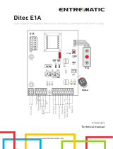
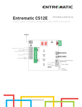
Ditec CS12E
Control panel installation manual for Ditec NEOS automations
www.ditecentrematic.com
IP2162EN
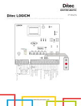
COM
Power supply
Release
microswitch
Selection of automation type
(FACTORY SET)
blue
black
grey
+
-
-
+
Closing safety device
Step-by-step
Flashing light
Antenna
Safety stop
MOTOR
24V
Output 24 V max 0,3 A
0168 15 +LP-
JR3
AUX
JR1
UP
DOWN
ENTER
ESC
STORAGE
MODULE
PLUG-IN CARD
NES100FCM
BAT
LSW
NES100BBU

52
IP2162EN - 2014-04-17

53
IP2162EN - 2014-04-17
Index
Subject Page
1. General safety precautions 54
2. EC Declaration of Conformity 55
3. Technical specifications 55
4. Commands 56
4.1 Inserting plug-in card (AUX) 57
4.2 Self-controlled safety edge 57
5. Outputs and accessories 59
6. Selections 60
7. Settings 60
7.1 Switching on and off 61
7.2 Key combinations 61
7.3 Main menu 62
7.4 Second level menu - AT (Automatic Configurations) 63
7.5 Second level menu - BC (Basic Configurations) 65
7.6 Second level menu - BA (Basic Adjustment) 67
7.7 Second level menu - RO (Radio Operations) 71
7.8 Second level menu - SF (Special Functions) 74
7.9 Second level menu - CC (Cycles Counter) 76
7.10 Second level menu - AP (Advanced Parameters) 78
8. Display visualisation mode 82
8.1 Display of automation status 82
8.2 Display of safety devices and commands 84
8.3 Display of alarms and faults 86
9. Start-up 89
10. Troubleshooting 90
11. Examples of application 92
Quick Reference 95
Key
i
This symbol indicates useful information for the correct functioning of the product.
Factory settings
This symbol indicates instructions or notes regarding safety, to which special atten-
tion must be paid.

54
IP2162EN - 2014-04-17
This installation manual is intended for qualified personnel only.
Installation, electrical connections and adjustments must be performed in accordance
with Good Working Methods and in compliance with the present standards.
Read the instructions carefully before installing the product. Bad installation could
be dangerous.
The packaging materials (plastic, polystyrene, etc.) should not be discarded in
the environment or left within reach of children, as these are a potential source
of danger.
Before installing the product, make sure it is in perfect condition.
Do not install the product in explosive areas and atmospheres: the presence of inflam-
mable gas or fumes represents a serious safety hazard.
The safety devices (photocells, safety edges, emergency stops, etc.) must be installed
taking into account: applicable laws and directives, Good Working Methods, instal-
lation premises, system operating logic and the forces developed by the automation.
Before connecting the power supply, make sure the plate data correspond to that
of the mains power supply. An omnipolar disconnection switch with minimum
contact gaps of 3 mm must be included in the mains supply.
Check that there is an adequate residual current circuit breaker and a suitable overcur-
rent cut-out upstream of the electrical installation in accordance with Good Working
Methods and with the laws in force.
When requested, connect the automation to an effective earthing system that complies
with current safety standards.
During installation, maintenance and repair operations, cut off the power supply before
opening the cover to access the electrical parts.
The electronic parts must be handled using earthed antistatic conductive arms.
The manufacturer of the motorisation declines all responsibility in the event
of component parts being fitted that are not compatible with the safe and correct
operation.
Use original spare parts only for repairing or replacing products.
1. General safety precautions
“Important instructions for installation safety.
Incorrect installation can cause serious injury”
1.1 Safety functions
The CS12E control panel has the following safety functions:
- obstacle recognition with force limiting;
The maximum response time of the safety functions is 0.5 s. The reaction time to a faulty safety
function is 0.5 s.
The safety functions comply with the standards and performance level indicated below:
EN ISO 13849-1:2008 Category 2 PL=c
EN ISO 13849-2:2012
The safety function cannot be bypassed either temporarily or automatically. Fault exclusion
has not been applied.

55
IP2162EN - 2014-04-17
The manufacturer Entrematic Group AB, with headquarters in Lodjursgatan 10, SE-261 44 Land-
skrona, Sweden, declares that the Ditec CS12E type control panel complies with the conditions
of the following EC directives:
EMC Directive 2004/108/EC
Low Voltage Directive 2006/95/EC
R&TTE Directive 1999/5/EC.
L a n d s k r o n a , 2 8 - 0 3 - 2 0 1 3 M a r c o Z i n i
(President & CEO)
2. EC Declaration of Conformity
3. Technical specifications
Description NES300EH NES400EH NES600EH
Power supply 230 V~ 50/60 Hz 230 V~ 50/60 Hz 230 V~ 50/60 Hz
Motor output 24 V 12 A max 24 V 14 A max 24 V 16 A max
Accessories power supply 24 V 0.3 A 24 V 0.3 A 24 V 0.3 A
Ambient temperature -20 °C - +55 °C -20 °C - +55 °C -20 °C - +55 °C
Storable radio codes 100
200 [BIXMR2]
100
200 [BIXMR2]
100
200 [BIXMR2]
Radio frequency 433.92 MHz 433.92 MHz 433.92 MHz
i
N.B.: The given operating and performance features can only be guaranteed with the
use of DITEC Entrematic accessories and safety devices.

56
IP2162EN - 2014-04-17
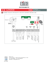
4. Commands
Command Function Description
1 5 NO STEP-BY-STEP
WITH AUTOMATIC
CLOSING
When selecting → → , closing the con-
tact starts a sequential opening or closing operation:
opening-stop-closing-opening.
WARNING: if automatic closing is enabled, the dura-
tion of the stop can be selected by selecting →
.
STEP-BY-STEP
WITHOUT AUTOMATIC
CLOSING
When selecting → → , closing the contact
starts a sequential opening or closing operation:
opening-stop-closing-opening.
OPENING
WITH AUTOMATIC
CLOSING
When selecting → → , closing the contact
activates an opening operation.
OPENING
WITHOUT
AUTOMATIC
CLOSING
When selecting → → , closing the contact
activates an opening operation.
N.B.: Once the automation stops, command 1-5 per-
forms the opposite operation to the one performed
before the stop.
1 6 NC CLOSING
SAFETY DEVICE
When selecting → → , opening of the safety
contact stops and prevents any movement.
N.B.: to set different safety contact functions, see the
→ parameter settings.
1 6 NO CLOSING When selecting → → , closing the contact
activates a closing operation.
1 8 NC CLOSING
SAFETY DEVICE
Opening the safety contact triggers a reversal of the
movement (reopening) during the closing operation.
When selecting → → , with the automa-
tion idle, opening of the contact prevents any opera-
tion.
When selecting → → , with the automa-
tion idle, opening of the contact only prevents clos-
ing.
WARNING: make a jumper for all NC contacts if not in use. The terminals with the same
number are equal.

57
IP2162EN - 2014-04-17
4.1 Inserting plug-in card (AUX)
UP
DOWN
ENTER
ESC
To access the plug-in card (AUX), cut the control panel cover as shown in the figure.
4.2 SOFA1-SOFA2 or GOPAVRS self-controlled safety edge
Command Function Description
GOPAV
SOFA1-SOFA2 SAFETY TEST Place the SOFA1-SOFA2 or GOPAVRS device into the
special housing for AUX plug-in cards.
If the test fails, an alarm message appears on the
display.
1 6 NC SAFETY STOP When selecting → → , connect the output
contact of the safety device to terminals 1-6 on the con-
trol panel (in series with the photocell output contact,
if installed).
1 8 NC CLOSING
SAFETY
DEVICE
When selecting → → , connect the output
contact of the safety device to terminals 1-8 on the con-
trol panel (in series with the photocell output contact,
if installed).

58
IP2162EN - 2014-04-17
SOFA15
SOFA20
SOFA25
SOFA15
SOFA20
SOFA25
IN1 IN2 +BC
GOPAVT
-
OPENING
JR3
AUX
51 +LP-0168
8K2
8K2
IN11 IN241
OUT1 OUT2
GOPAVRS
CS12E
Examples of installation of self-controlled safety edge
SOFA15
SOFA20
SOFA25
OPENING
JR3
AUX
51 +LP-0168
IN11 IN241
OUT1 OUT2
SOFA1-A2
CS12E
SOFA15
SOFA20
SOFA25

59
IP2162EN - 2014-04-17
5. Outputs and accessories
Output Value
Accessories Description
0
-
1
+
24 V 0.3 A
Accessories power supply.
External accessories power supply output.
N.B.: the maximum absorption of 0.3 A corresponds to the
sum of all terminals 1.
GOL148REA
(433, 92 MHz)
Antenna connection (433, 92 MHz).
If the inside radio receiver is used, connect the supplied antenna
wire (173 mm), or alternatively the GOL148REA antenna, using a
coaxial cable, type RG58.
+LP- LAMPH
24 V 25 W
Flashing light.
The pre-flashing settings can be selected from the third level
menu → and/or → .
AUX
The control panel has a housing for plug-in cards.
The action of the card can be selected by selecting → .
WARNING: the plug-in cards must be inserted and removed
with the power supply disconnected.
COM
BIXMR2
This allows the functioning configurations to be saved using
the function → .
The saved configurations can be recalled using the function
→ .
The storage module allows the remote controls to be stored.
If the control panel is replaced, the storage module being
used can be inserted in the new control panel.
WARNING: the storage module must be inserted and re-
moved with the power supply disconnected.
LSW NES100FCM
Magnetic limit switch kit (optional only for Ditec NES300 -
NES400).
BAT
NES100BBU
2x12 V 2Ah
BAT - Batteries functioning.
The batteries are kept charged when the power supply is on. If
the power supply is off, the panel is powered by the batteries
until the power is re-establish or until the battery voltage drops
below the safety threshold. The panel turns off in the last case.
WARNING: the batteries must always be connected to the
control panel for charging. Periodically check the efficiency of
the batteries.
N.B.: the operating temperature of the rechargeable batteries is
approximately +5°C/+40°C.
Mains power supply, motor, release microswitch and automa-
tion wiring connection.

60
IP2162EN - 2014-04-17
The procedure to switch on the display is as follows:
ǩ SUHVVWKH(17(5NH\
ǩ WKHGLVSOD\IXQFWLRQLQJFKHFNVWDUWV
ǩ WKHȌUVWOHYHOPHQXLVGLVSOD\HG
The procedure to switch off the display is as follows:
ǩ SUHVVWKH(6&NH\
N.B.: the display switches off automatically after 60 s of inactivity.
7. Settings
7.1 Switching the display on and off
i
N.B.: pressure on the keys can be quick (less than 2 s) or prolonged (longer than 2 s).
Unless specified otherwise, quick pressure is intended.
6. Selections
Jumper Description OFF ON
JR1 Display mode selection. Display mode.
Only the values and pa-
rameters present can be
displayed.
Maintenance mode.
Only the values and pa-
rameters present can be
displayed and modified.
Going into maintenance
mode is indicated by the
permanent switching on of
the right-hand point on the
display.
JR3 Built-in radio receiver. Disabled. Enabled.

61
IP2162EN - 2014-04-17
ǩ Simultaneous pressing of the keys ↑and ENTER performs an opening com-
mand.
ǩ Simultaneous pressing of the keys ↓and ENTER performs a closing command.
ǩ Simultaneous pressing of the keys ↑ and ↓ performs a POWER RESET com-
mand. (interruption of the power supply and restart of the automation).
ǩ Keeping press the UP ↑ or DOWN ↓ key, fast menu scrolling begin. To stop
menu scrolling.
ǩ In some menus, the parameter unit of measurement can be displayed by press-
ing the ENTER key once the value has been displayed (in the example, 50 cm).
7.2 Key combinations

62
IP2162EN - 2014-04-17
ǩ XVLQJNH\VǴDQGǶVHOHFWWKHGHVLUHGIXQFWLRQ
ǩ SUHVVWKH(17(5NH\WRFRQȌUP
After confirming the selection, you access the second level menu.
7.3 Main menu
Display Description
AT - Automatic Configurations.
The menu allows you to manage the automatic configurations of the control
panel.
BC - Basic Configurations.
The menu allows you to display and modify the main settings of the control panel.
BA - Basic Adjustments.
The menu allows you to display and modify the main adjustments of the con-
trol panel.
N.B.: some settings require at least three operations before they are set
correctly.
RO - Radio Operations.
The menu allows you to manage the radio operations of the control panel.
SF - Special Functions.
The menu allows you to set the password and manage the special functions
in the control panel.
CC - Cycles Counter.
The menu allows you to display the number of operations carried out by the
automation and manage the maintenance interventions.
AP - Advanced Parameters.
The menu allows you to display and modify the advanced settings and adjust-
ments of the control panel.
N.B.: some settings require at least three operations before they are set
correctly.
WARNING: depending on the type of automation and control panel, some menus may
not be available.

63
IP2162EN - 2014-04-17
ǩ XVLQJNH\VǴDQGǶVHOHFWWKHGHVLUHGIXQFWLRQ
ǩ SUHVVWKH(17(5NH\WRFRQȌUP
7.4 Second level menu
AT (Automatic Configurations)
Display Description
RT - Opening to right.
LF - Opening to left.
H0 - Predefined setting, residential use 0.
This selection loads predefined values for certain standard parameters:
AC - enabling of automatic closing : disabled
C5 - step-by-step/opening command operation : step-by-step
RM - remote control operation : step-by-step
AM - AUX plug-in card operation : step-by-step
SS - Selection of automation status at start-up : open
H1 - Predefined setting, residential use 1.
This selection loads predefined values for certain standard parameters:
AC - enabling of automatic closing : enabled
TC - setting of automatic closing time : 1 minute
C5 - step-by-step/opening command operation : step-by-step
RM - remote control operation : step-by-step
AM - AUX plug-in card operation : step-by-step
SS - Selection of automation status at start-up : closed
C0 - Predefined setting, condominium use 0.
This selection loads predefined values for certain standard parameters:
AC - enabling of automatic closing : enabled
TC - setting of automatic closing time : 1 minute
C5 - step-by-step/opening command operation : opening
RM - remote control operation : opening
AM - AUX plug-in card operation : opening
SS - Selection of automation status at start-up : closed
RD - Resetting of general settings (SETTINGS RESET).
→
2”

64
IP2162EN - 2014-04-17
Display Description
AA - Activating advanced parameters menu.
→
2”
After activation you can scroll through the third level
menus.
The third level menus are activated for 30 min.
Depending on the type of automation and control panel, some menus may not be avail-
able.

65
IP2162EN - 2014-04-17
ǩ XVLQJNH\VǴDQGǶVHOHFWWKHGHVLUHGIXQFWLRQ
ǩ SUHVVWKH(17(5NH\WRFRQȌUP
7.5 Second level menu - BC (Basic Configurations)
Display Description
AC - Enabling of automatic closing.
ON - Enabled
OF - Disabled
SS - Selection of automation status at start.
OP - Open
CL - Closed
Indicates how the control panel considers the automa-
tion at the time of switch-on, or after a POWER RESET
command.
SO - Enabling of reversal safety contact functioning.
ON - Enabled
OF - Disabled
When enabled (ON) with the automation idle, if the
contact 1-8 is open, all operations are prevented.
When disabled (OF) with the automation idle, if the
contact 1-8 is open, opening operations are permitted.
NI - Enabling of NIO electronic anti-freeze system.
ON - Enabled
OF - Disabled
When enabled (ON) it maintains motor efficiency even
at low ambient temperatures, increases the starting
time to the maximum value and reduces the ac-
celeration time to the minimum value.
N.B.: for correct operation, the control panel must be
exposed to the same ambient temperature as the mo-
tors.
WARNING: depending on the type of automation and control panel, some menus may
not be available.

66
IP2162EN - 2014-04-17
7.5.1 Third level menu - BC (Basic Configurations)
Access the third level menu by activating function (see paragraph 7.4)
Display Description
HR - Enabling of operator present function
ON - Enabled
OF - Disabled
N.B.: Set → only if → and → .
64 - Functioning of safety stop/closing command.
1-4 - Closing
1-6 - Safety stop
C5 - Step-by-step/opening command operation.
1-5 - Step-by-step
1-3 - Opening
RM - Radio receiver operation.
1-5 - Step-by-step
1-3 - Opening
AM - AUX plug-in card operation.
1-5 - Step-by-step
1-3 - Opening
PP - Setting step-by-step sequence from command
1-5.
ON - Opening-Stop-Closing-Stop-Opening
OF - Opening-Stop-Closing-Opening
S5 - Duration of STOP in step-by-step sequence from
command 1-5.
ON - Permanent
OF - Temporary
OD - Selecting opening direction.
LF - Opening to left.
RT - Opening to right.
The opening direction is intended by viewing the auto-
mation from the side being examined.
N.B.: Modification of status from RT to LF and vice
versa performs an automatic RESET of the card.

67
IP2162EN - 2014-04-17
ǩ XVLQJNH\VǴDQGǶVHOHFWWKHGHVLUHGIXQFWLRQ
ǩ SUHVVWKH(17(5NH\WRFRQȌUP
7.6 Second level menu - BA (Basic Adjustment)
Display Description
MT - Display of type of automation.
N3 - Motor with 300 kg capacity
N4 - Motor with 400 kg capacity
N6 - Motor with 600 kg capacity
N.B.: this parameter is DISPLAY only.
TC - Setting of automatic closing time. [s]
It is set with different intervals of sensitivity.
ǩ from 0” to 59” with intervals of 1 second;
ǩ from 1’ to 2’ with intervals of 10 seconds.
1’00”
RP - Adjustment of partial opening measurement.
[%]
Adjusts the percentage of operation in relation to the
total opening of the automation.
10 - Minimum
99 - Maximum 30
TP - Setting of automatic closing time after partial
opening. [s]
It is set with different intervals of sensitivity.
ǩ from 0” to 59” with intervals of 1 second;
ǩ from 1’ to 2’ with intervals of 10 seconds.
00’30’’
VA - Setting of opening speed. [cm/s]
N.B.:
24 - Maximum with →
25 - Maximum with → or 15
VC - Setting of closing speed. [cm/s]
N.B.:
24 - Maximum with →
25 - Maximum with → or 15

68
IP2162EN - 2014-04-17
Display Description
R2 - Adjustment of thrust on obstacles and current
during opening [%]
The control panel is equipped with a safety device that
stops movement if an obstacle is detected during an
opening operation with disengagement of 10 cm.
00 - Minimum thrust
99 - Maximum thrust
50
R1 - Adjustment of thrust on obstacles and current
during closing [%]
The control panel is fitted with a safety device which
stops or reverses movement when an obstacle is de-
tected during a closing operation.
00 - Minimum thrust
99 - Maximum thrust
50
WARNING: depending on the type of automation and control panel, some menus may
not be available.
i
N.B.: make adjustments gradually and only after performing at least three complete
operations to allow the control panel to be set correctly and detect any friction during
operations.

69
IP2162EN - 2014-04-17
7.6.1 Third level menu - BA (Basic Adjustment)
Access the third level menu by activating function (see paragraph 7.4)
Display Description
DT - Adjustment of obstacle recognition time. [s/100]
10 - Minimum
60 - Maximum
N.B.: the parameter is adjusted in hundredths of a
second. 40
MP - Start at maximum power
ON - During start-up it increases the thrust on obsta-
cles to maximum.
OFF - During start-up the thrust on obstacles is that
adjusted by -
ST - Adjustment of start time. [s]
0.5 - Minimum
3.0 - Maximum 2.0
TA - Adjustment of acceleration time. [s]
0.5 - Minimum (start speed is 75% of - )
2.0 - Maximum 1.5
TD - Adjustment of deceleration time. [%]
10 - Minimum
99 - Maximum 75
OB - Adjustment of deceleration distance during
opening. [cm]
Indicates the distance from the end of the opening
stroke where the deceleration ramp begins.
05 - Minimum
99 - Maximum
N.B.: reduce the deceleration space if there is a series
of quick vibrations (chattering) in heavy gates installed
with a slight incline.
40
OB - Adjustment of deceleration distance during
closing. [cm]
Indicates the distance from the end of the closing
stroke where the deceleration ramp begins.
05 - Minimum
99 - Maximum
N.B.: reduce the deceleration space if there is a series
of quick vibrations (chattering) in heavy gates installed
with a slight incline.
40

70
IP2162EN - 2014-04-17
Display Description
PO - Adjustment of approach speed during opening.
[cm/s]
Indicates the speed from the end of the deceleration
ramp to the end of the stroke.
02 - Minimum
10 - Maximum
N.B.: gradually increase the approach speed if there is
a series of quick vibrations (chattering) in heavy gates
installed with a slight incline.
03
PC - Adjustment of approach speed during closing.
[cm/s]
Indicates the speed from the end of the deceleration
ramp to the end of the stroke.
02 - Minimum
10 - Maximum
N.B.: gradually increase the approach speed if there is
a series of quick vibrations (chattering) in heavy gates
installed with a slight incline.
03
OO - Obstacle detection limit during opening [cm]
Indicates the distance from the end of the opening
stroke after which each obstacle is considered a stop.
05 - Minimum
99 - Maximum
N.B.: This parameter is only active if → → 40
OC - Obstacle detection limit during closing [cm]
Indicates the distance from the end of the closing
stroke after which each obstacle is considered a stop.
05 - Minimum
99 - Maximum
N.B.: This parameter is only active if → → 40
i
N.B.: make adjustments gradually and only after performing at least three complete
operations to allow the control panel to be set correctly and detect any friction during
operations.
/