Denon AVR-A100 User guide

Category
AV receivers
Type
User guide
AV SURROUND RECEIVER
AVR-A100
Owners Manual
Manuel de l’Utilisateur
Simple
version
Version simplifi ée
v
4
Basic
version
Version basique
v
14
Advanced
version
Version avancée
v
53
Information
“Part names and functions”
(vpage120)
v
119
Informations
“Nomenclature et fonctions“
(vpage120)
1.AVRA100E3_ENG_1st_0824.indd 1 2010/08/26 17:47:06
1.AVRA100E3_ENG_1st_0824.indd 2 2010/08/26 17:47:06
I
n
SAFETY PRECAUTIONS
CAUTION
RISK OF ELECTRIC SHOCK
DO NOT OPEN
CAUTION:
TO REDUCE THE RISK OF ELECTRIC SHOCK, DO NOT REMOVE
COVER (OR BACK). NO USER-SERVICEABLE PARTS INSIDE.
REFER SERVICING TO QUALIFIED SERVICE PERSONNEL.
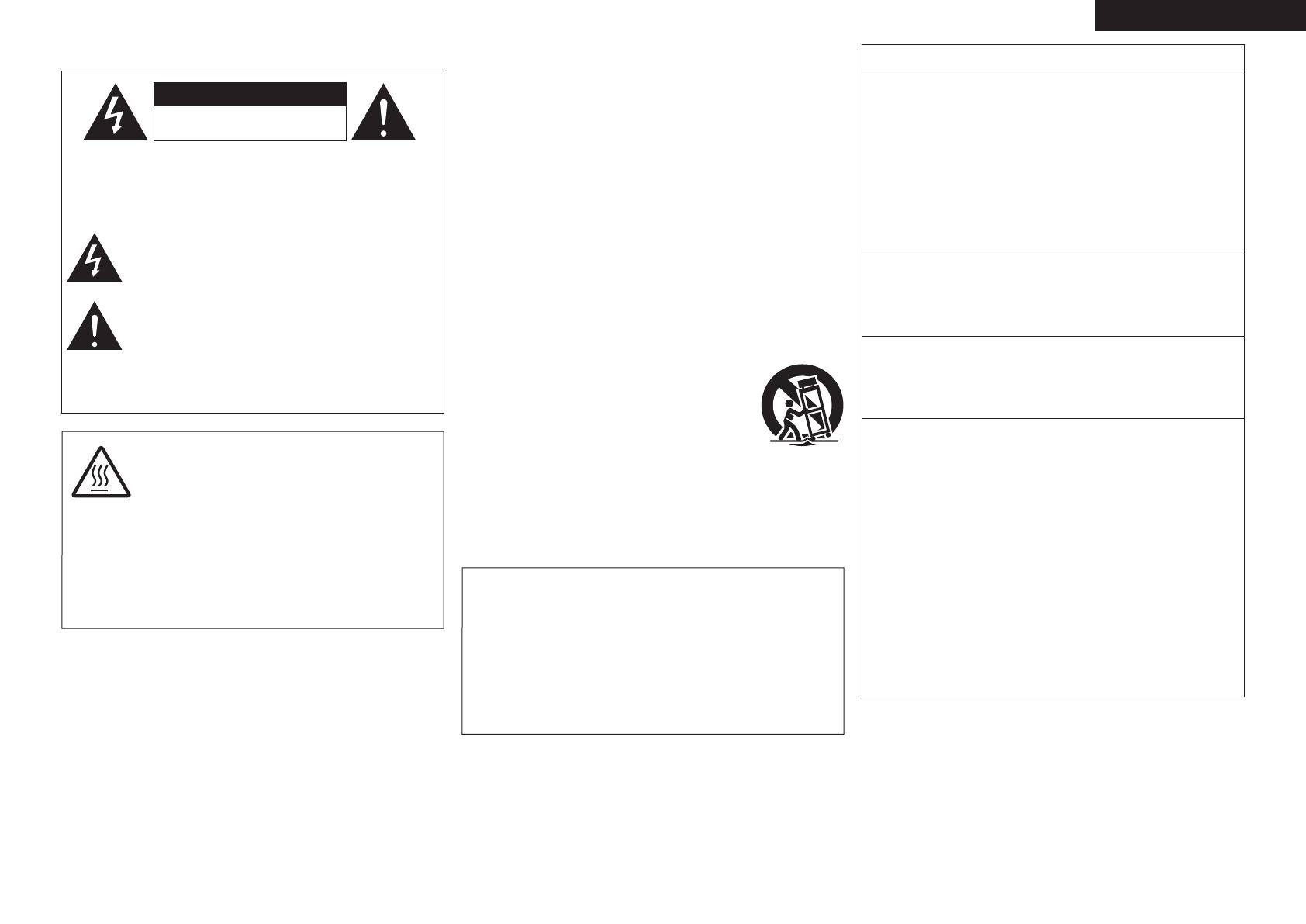
The lightning flash with arrowhead symbol, within an equilateral
triangle, is intended to alert the user to the presence of
uninsulated “dangerous voltage” within the product’s enclosure
that may be of sufficient magnitude to constitute a risk of
electric shock to persons.
The exclamation point within an equilateral triangle is intended
to alert the user to the presence of important operating
and maintenance (servicing) instructions in the literature
accompanying the appliance.
WARNING:
TO REDUCE THE RISK OF FIRE OR ELECTRIC SHOCK, DO NOT
EXPOSE THIS APPLIANCE TO RAIN OR MOISTURE.
CAUTION:
To completely disconnect this product from the mains, disconnect the plug
from the wall socket outlet.
The mains plug is used to completely interrupt the power supply to the unit
and must be within easy access by the user.
PRECAUTION:
Pour déconnecter complètement ce produit du courant secteur, débranchez
la prise de la prise murale.
La prise secteur est utilisée pour couper complètement l’alimentation de
l’appareil et l’utilisateur doit pouvoir y accéder facilement.
IMPORTANT SAFETY
INSTRUCTIONS
1. Read these instructions.
2. Keep these instructions.
3. Heed all warnings.
4. Follow all instructions.
5. Do not use this apparatus near water.
6. Clean only with dry cloth.
7. Do not block any ventilation openings.
Install in accordance with the manufacturer’s instructions.
8. Do not install near any heat sources such as radiators, heat registers,
stoves, or other apparatus (including amplifiers) that produce heat.
9. Do not defeat the safety purpose of the polarized or grounding-type plug. A
polarized plug has two blades with one wider than the other. A grounding
type plug has two blades and a third grounding prong. The wide blade or the
third prong are provided for your safety. If the provided plug does not fit into
your outlet, consult an electrician for replacement of the obsolete outlet.
10. Protect the power cord from being walked on or pinched particularly at
plugs, convenience receptacles, and the point where they exit from the
apparatus.
11. Only use attachments/accessories specified by the manufacturer.
12. Use only with the cart, stand, tripod, bracket, or table
specified by the manufacturer, or sold with the apparatus.
When a cart is used, use caution when moving the cart/
apparatus combination to avoid injury from tip-over.
13. Unplug this apparatus during lightning storms or when
unused for long periods of time.
14. Refer all servicing to qualified service personnel.
Servicing is required when the apparatus has been damaged in any way,
such as power-supply cord or plug is damaged, liquid has been spilled or
objects have fallen into the apparatus, the apparatus has been exposed to
rain or moisture, does not operate normally, or has been dropped.
15. Batteries shall not be exposed to excessive heat such as sunshine, fire or
the like.
FCC INFORMATION (For US customers)
1. COMPLIANCE INFORMATION
Product Name: AV Surround Receiver
Model Number: AVR-A100
This product complies with Part 15 of the FCC Rules. Operation is subject
to the following two conditions: (1) this product may not cause harmful
interference, and (2) this product must accept any interference received,
including interference that may cause undesired operation.
Denon Electronics (USA), LLC
(a D & M Holdings Company)
100 Corporate Drive
Mahwah, NJ 07430-2041
Tel. (800) 497-8921
2. IMPORTANT NOTICE: DO NOT MODIFY THIS PRODUCT
This product, when installed as indicated in the instructions contained
in this manual, meets FCC requirements. Modification not expressly
approved by DENON may void your authority, granted by the FCC, to use
the product.
3. IMPORTANT
When connecting this product to network hub or router, use only shielded
STP or ScTP LAN cables which is available at retailer.
Follow all installation instructions. Failure to follow instructions could void
your authority, granted by the FCC, to use the product.
4. NOTE
This product has been tested and found to comply with the limits for
a Class B digital device, pursuant to Part 15 of the FCC Rules. These
limits are designed to provide reasonable protection against harmful
interference in a residential installation.
This product generates, uses and can radiate radio frequency energy and,
if not installed and used in accordance with the instructions, may cause
harmful interference to radio communications. However, there is no
guarantee that interference will not occur in a particular installation. If this
product does cause harmful interference to radio or television reception,
which can be determined by turning the product OFF and ON, the user
is encouraged to try to correct the interference by one or more of the
following measures:
• Reorient or relocate the receiving antenna.
• Increase the separation between the equipment and receiver.
• Connect the product into an outlet on a circuit different from that to
which the receiver is connected.
• Consult the local retailer authorized to distribute this type of product or
an experienced radio/TV technician for help.
For Canadian customers:
This Class B digital apparatus complies with Canadian ICES-003.
Cet appareil numérique de la classe B est conforme à la norme NMB-003 du
Canada.
CAUTION:
HOT SURFACE. DO NOT TOUCH.
The top surface over the internal heat sink may become hot
when operating this product continuously.
Do not touch hot areas, especially around the “Hot surface
mark” and the top panel.
PRECAUTION:
SURFACE CHAUDE. NE PAS TOUCHER.
La surface supérieure du dissipateur de chaleur peut devenir
chaude si vous utilisez ce produit en continu.
Ne touchez pas les zones chaudes, tout particulièrement vers
l’inscription “Hot surface mark” et le panneau supérieur.
Hot
surface
mark
ENGLISHFRANCAIS
1.AVRA100E3_ENG_1st_0824.indd 1 2010/08/26 17:47:07
II
n
NOTES ON USE / OBSERVATIONS RELATIVES A L’UTILISATION
WARNINGS AVERTISSEMENTS
• Avoid high temperatures.
Allow for sufficient heat dispersion when installed in a rack.
• Handle the power cord carefully.
Hold the plug when unplugging the cord.
• Keep the unit free from moisture, water, and dust.
• Unplug the power cord when not using the unit for long periods of time.
• Do not obstruct the ventilation holes.
• Do not let foreign objects into the unit.
• Do not let insecticides, benzene, and thinner come in contact with the unit.
• Never disassemble or modify the unit in any way.
• Ventilation should not be impeded by covering the ventilation openings with
items, such as newspapers, tablecloths or curtains.
• Naked flame sources such as lighted candles should not be placed on the
unit.
• Observe and follow local regulations regarding battery disposal.
• Do not expose the unit to dripping or splashing fluids.
• Do not place objects filled with liquids, such as vases, on the unit.
• Do not handle the mains cord with wet hands.
• When the switch is in the OFF position, the equipment is not completely
switched off from MAINS.
• The equipment shall be installed near the power supply so that the power
supply is easily accessible.
• Eviter des températures élevées.
Tenir compte d’une dispersion de chaleur suffisante lors de l’installation sur
une étagère.
• Manipuler le cordon d’alimentation avec précaution.
Tenir la prise lors du débranchement du cordon.
• Protéger l’appareil contre l’humidité, l’eau et la poussière.
• Débrancher le cordon d’alimentation lorsque l’appareil n’est pas utilisé
pendant de longues périodes.
• Ne pas obstruer les trous d’aération.
• Ne pas laisser des objets étrangers dans l’appareil.
• Ne pas mettre en contact des insecticides, du benzène et un diluant avec
l’appareil.
• Ne jamais démonter ou modifier l’appareil d’une manière ou d’une autre.
• Ne pas recouvrir les orifices de ventilation avec des objets tels que des
journaux, nappes ou rideaux. Cela entraverait la ventilation.
• Ne jamais placer de flamme nue sur l’appareil, notamment des bougies
allumées.
• Veillez à respecter les lois en vigueur lorsque vous jetez les piles usagées.
• L’appareil ne doit pas être exposé à l’eau ou à l’humidité.
• Ne pas poser d’objet contenant du liquide, par exemple un vase, sur
l’appareil.
• Ne pas manipuler le cordon d’alimentation avec les mains mouillées.
• Lorsque l’interrupteur est sur la position OFF, l’appareil n’est pas
complètement déconnecté du SECTEUR (MAINS).
• L’appareil sera installé près de la source d’alimentation, de sorte que cette
dernière soit facilement accessible.
n CAUTIONS ON INSTALLATION
PRÉCAUTIONS D’INSTALLATION
z z
z
Wall
Paroi
z
zFor proper heat dispersal, do not install this unit in a confined
space, such as a bookcase or similar enclosure.
• More than 0.3 m (12 in.) is recommended.
• Do not place any other equipment on this unit.
zPour permettre la dissipation de chaleur requise, n’installez
pas cette unité dans un espace confiné tel qu’une bibliothèque
ou un endroit similaire.
• Une distance de plus de 0,3 m (12 po) est recommandée.
• Ne placez aucun matériel sur cet appareil.
FRANCAISENGLISH
1.AVRA100E3_ENG_1st_0824.indd 2 2010/08/26 17:47:07
1
Basic versionSimple version Advanced version Information
ENGLISH
Contents
Thank you for purchasing this DENON product. To ensure proper operation, please read these owner’s manual carefully before using the product.
After reading them, be sure to keep them for future reference.
Getting started
Simple version (Simple setup guide) ··························4
Basic version ··········································································14
Connections ·················································································15
Important information ·································································15
Connecting an HDMI-compatible device ····································16
Connecting a TV··········································································18
Connecting a Blu-ray Disc player ················································18
Connecting a DVD player ····························································19
Connecting a set-top box (Satellite tuner/cable TV) ····················19
Connecting a digital video recorder ············································20
Connecting a digital camcorder ··················································21
Connecting a control dock for iPod ·············································21
Connecting an iPod or USB memory device to the USB port ·····22
Connecting an antenna ·······························································23
Connecting a record player ·························································24
Connecting a CD player ······························································24
Component equipped with a DENON LINK connector ···············25
Component with Multi-channel Output connectors ···················25
Connecting a external power amplifier ·······································25
Connecting to a home network (LAN) ········································26
Connecting an external control device ········································27
Playback (Basic operation) ·························································28
Important information ·································································28
Playing a Blu-ray Disc player/DVD player ····································29
Playing a CD player ·····································································30
Playing an iPod
®
·········································································30
Tuning in radio stations ·······························································33
Playing a network audio ······························································37
Playing a USB memory device ····················································48
Selecting a listening mode (Surround Mode) ··························50
Standard playback ·······································································50
DENON original surround playback ·············································52
Stereo playback ··········································································52
Direct playback ···········································································52
Pure direct playback····································································52
Advanced version ·······························································53
Speaker installation/connection (Advanced connection) ·······54
Install ··························································································54
Connect ······················································································56
Set up speakers ··········································································63
Playback (Advanced operation) ·················································65
Convenient functions ··································································65
Playback in ZONE2/ZONE3 (Separate room) ··························72
Audio output ···············································································72
Video output ···············································································72
Playback ······················································································73
Menu Operation··········································································73
Quick select function ··································································74
Sleep timer function ···································································74
How to make detailed settings ··················································75
Menu map ··················································································75
Examples of menu screen displays ············································76
Examples of menu and front display ··········································77
Inputting characters ···································································78
SOURCE SELECT ·······································································80
AUDIO/VIDEO ADJUST ······························································86
MANUAL SETUP ········································································93
INFORMATION ·········································································107
Operating the connected devices by remote control unit ····108
Operating the main remote control unit ···································108
Operating the sub remote control unit ·····································115
Information ···········································································119
Part names and functions·························································120
Front panel ················································································120
Display ······················································································121
Rear panel ·················································································122
Remote control unit ··································································123
Other information ·····································································125
Trademark information ······························································125
Surround ···················································································126
Relationship between video signals and monitor output ··········131
Explanation of terms ·································································132
Troubleshooting ········································································135
Resetting the microprocessor ··················································138
Specifications ············································································139
Getting started ··············································································1
Accessories ··················································································2
About this manual ·········································································2
Features ························································································2
Cautions on handling ····································································3
1.AVRA100E3_ENG_1st_0824.indd 1 2010/08/26 17:47:07
2
ENGLISH
Features
Fully Discrete, identical quality and power for all
9 channels (170 W x 9ch)
The unit is equipped with a power amplifi er that reproduces high-
delity sound in surround mode with equal quality and power for all
channels, true to the original sound.
The power amplifi er circuit adopts a discrete-circuit confi guration
that achieves high-quality surround sound reproduction.
Supports HDMI 1.4a with 3D, ARC, Deep Color,
x.v.Color , Auto Lipsync and HDMI control function
This unit can output 3D video signals input from a Blu-ray Disc
player to a TV that supports a 3D system. This unit also supports
the ARC (Audio Return Channel) function, which reproduces TV
sound with this unit via an HDMI cable used for connecting the
unit and a TV
z1
.
z1 The TV should support the ARC function.
Internet radio, music and photo streaming via
network
z2
This unit can playback audio les and still images such as
photographs that are stored on your computer via a network. You
can also listen to internet radio and a whole host of other online
music
z3
that uses network technology.
z2 An internet connection is required.
z3 You may be required to sign a service agreement with the
companies that provide particular services.
7-HDMI inputs and 2-outputs
The unit is equipped with 7 HDMI input connectors for connecting
devices with HDMI connectors, such as a Blu-ray Disc player,
game machine, HD video camera, etc.
Dolby Volume
Dolby Volume measures, analyzes, and maintains volume levels
based on how people perceive sound. It examines a variety of
audio parameters to maintain consistent playback levels whether
switching between channels or between multiple source inputs.
A sophisticated combination of spectral- and time-based loudness
analysis enables it to quickly and properly correct level differences
without creating compression artifacts or undesirable pumping in
the audio signal.
DENON LINK 4th support
When you connect this unit to a Denon Blu-ray disc player that
has DENON LINK 4th support, you can enjoy HD audio of the
highest quality. The master clock that operates the D/A converter
of this unit is transmitted to the Blu-ray disc player, enabling the
integrated circuitry to be operated while sharing the same clock
in order to achieve digital audio transmission with negligible jitter.
Sound localization becomes clearer and a greater sense of space is
produced in the sound images.
High defi nition audio support
The unit is equipped with a decoder which supports high-quality
digital audio format for Blu-ray Disc players such as Dolby TrueHD,
DTS-HD Master Audio, etc.
Audyssey MultEQ
®
XT 32
Audyssey MultEQ corrects both time and frequency response
problems in the listening area so that every listener can enjoy
music and movie with the optimum sounds. It performs a fully
automated surround system setup. The unit is equipped Audyssey
MultEQ XT 32 that can correct much higher details, particularly
in the bass range of the speakers. The high resolution correction
reproduces much clearer surround sound.
Discrete subwoofers and Audyssey multiple
subwoofer calibration
The unit has two subwoofer output capability and can adjust the
level and delay for each subwoofer individually. Audyssey multiple
subwoofer calibration optimizes the level, delay, and frequency
response blending of two subwoofers. It eliminates the phase
cancellations between two subwoofers. The optimized sound
reporoduces more powerful sound.
Audyssey DSX™
This unit is equipped with Audyssey DSX processor. By connecting
front height speakers to this unit and playing back through Audyssey
DSX, you can experience a more powerful playback expression in
the height audio range. By connecting front wide speakers, you
can experience a more powerful playback expression in the wide
audio range.
Accessories
Check that the following parts are supplied with the product.
q Owner’s manual ...................................................................... 1
w Warranty (for North America model only) ................................ 1
e Service network list ................................................................. 1
r Power cord (Cord length: Approx. 6.2 ft / 1.9 m) ....................1
t Main remote control unit (RC-1145) ........................................ 1
y R6/AA batteries (for RC-1145) ................................................. 2
u Sub remote control unit (RC-1148) .......................................... 1
i R03/AAA batteries (for RC-1148) ............................................. 2
o Setup microphone
(DM-A409, Cord length: Approx. 19.7 ft / 6.0 m) ....................1
Q0 AM loop antenna (for HD Radio broadcasts) ........................... 1
Q1 FM indoor antenna (for HD Radio broadcasts) ........................1
tr
Q0 Q1
u
o
About this manual
n Operation buttons
The operations described in this manual are based mainly on
remote control operation.
n Symbols
Items for which this mark is indicated at the title can
be operated from the GUI menu.
We recommend performing such operations from
the GUI menu.
v
This symbol indicates a reference page on which
related information is described.
This symbol indicates a supplementary information
and tips for operations.
NOTE
This symbol indicates a supplementary information
and tips for operations.
n Illustrations
Note that the illustrations in these instructions are for explanation
purposes and may differ from the actual unit.
1.AVRA100E3_ENG_1st_0824.indd 2 2010/08/26 17:47:10
3
Basic versionSimple version Advanced version Information
ENGLISH
Cautions on handling
Before turning the power switch on
Check once again that all connections are correct and that there are
no problems with the connection cables.
Power is supplied to some of the circuitry even when the unit is
set to the standby mode. When going on vacation or leaving home
for long periods of time, be sure to unplug the power cord from the
power outlet.
About condensation
If there is a major difference in temperature between the inside of
the unit and the surroundings, condensation (dew) may form on
the operating parts inside the unit, causing the unit not to operate
properly.
If this happens, let the unit sit for an hour or two with the power
turned off and wait until there is little difference in temperature
before using the unit.
Cautions on using mobile phones
Using a mobile phone near this unit may result in noise. If that
occurs, move the mobile phone away from this unit when it is in use.
Moving the unit
Turn off the power and unplug the power cord from the power
outlet. Next, disconnect the connection cables to other system units
before moving the unit.
About Care
Wipe the cabinet and control panel clean with a soft cloth.
Follow the instructions when using a chemical cleaner.
Benzene, paint thinner or other organic solvents as well as
insecticide may cause material changes and discoloration if brought
into contact with the unit, and should therefore not be used.
Features
Easy to use, Graphical User Interface
This unit is equipped with an easy to see “Graphical User
Interface” that uses menu displays and levels. The use of level
displays increases operability of the this unit.
All sources are up-scaled to 1080p
The unit is provided with an HDMI video up-scaling function that
converts an analog video signal input to the unit to a 1080p (HD
resolution) signal and supplies it to a TV via the HDMI connector.
This enables the unit and a TV connected with a single HDMI cable
and any video source to be reproduced precisely with HD level of
quality.
Direct play for iPod
®
and iPhone
®
via USB
Music data from an iPod can be played back if you connect the
USB cable supplied with the iPod via the USB port of this unit, and
also an iPod can be controlled with the remote control unit for this
unit.
When an iPod is connected, merely pressing iPod PLAY on the
main unit or remote control unit starts playback of music from the
iPod.
Simultaneous playback on two HDMI channels
This unit is equipped with two HDMI MONITOR outputs. You can
connect one output to a projector and the other output to a TV for
simultaneous signal outputs.
1.AVRA100E3_ENG_1st_0824.indd 3 2010/08/26 17:47:11
Simple
version
4
ENGLISH
Simple version (Simple setup guide)
Here, we explain the entire setup procedure, from unboxing the unit to using it in a home theater.
The “Simple version” section provides the speaker installation, connection, and setup methods for the 7.1-channel system with surround
back speakers. For the installing, connecting, and setup methods of speakers other than the 7.1-channel system (with surround back
speakers), see page 54.
n Before connecting the unit, turn off the power to all devices.
n For operation of the connected devices, refer to the user manuals for each device.
Play back
disc
(vpage13)
Enjoy Blu-ray Disc in
surround sound.
5
Set up
speakers
(vpage7)
Use the setup microphone
(DM-A409) included
with the product, for
automatic setup.
4
Finish
STEP 6
Store
STEP 5
Check
STEP 4
Calculation
STEP 3
Measurement
(2nd – 8th listening position)
STEP 2
Detection &
Measurement
(Main listening position)
STEP 1
Preparation
Set up speakers (Audyssey
®
Auto Setup)
Turn on
power
(vpage7)
3
Connect
(vpage5)
Connect 7.1-channel
speakers, a TV and
Blu-ray Disc player
equipped with an HDMI
connector.
2
Install
(vpage5)
Enjoy better audio, using
the correct install method.
1
1.AVRA100E3_ENG_1st_0824.indd 4 2010/08/26 17:47:11
5
Basic version Advanced version Information
ENGLISH
Simple version
Speakers
Carefully check the left (L) and right (R)
channels and + (red) and (black) polarities
on the speakers being connected to the
this unit, and be sure to interconnect the
channels and polarities correctly.
Connecting the speaker cables
Peel off about 0.03 ft/10 mm of sheathing from
the tip of the speaker cable, then either twist the
core wire tightly or terminate it.
When using a banana plug
Tighten the speaker terminal rmly before
inserting the banana plug.
NOTE
Connect so that the speaker cable core wires
do not protrude from the speaker terminal.
The protection circuit may be activated if the
core wires touch the rear panel or if the + and
sides touch each other (vpage134 “Protection
Circuit”).
Never touch the speaker terminals while the
power supply is connected. Doing so could
result in electric shock.
Use speakers with the speaker impedances
shown below.
Speaker terminals
Speaker
impedance
FRONT
4 – 16 Ω
CENTER
SURROUND
SURR. BACK / AMP ASSIGN
F.HEIGHT / AMP ASSIGN
F.WIDE / AMP ASSIGN
Use speakers where one speaker has an
impedance of 4 to 16 Ω.
When using a speaker with impedance of 4 Ω or
6 Ω, make sure to set the “Speaker Impedance”
in the menu (vpage98) to “6 Ω/ohms” or “4 Ω/
ohms”.
Install
1 2 3 4 5
This unit can perform 2.0 to 11.2-channel surround playback.
This page provides the speaker installation procedure for the
7.1-channel playback using surround back speakers as an example.
FL FR
C
SBL SBR
SL
SR
SW
90 – 11
22 – 30˚
135 – 150˚
Listening
position
FL Front speaker (L) Install the surround speakers in a position 2 to
3 ft (60 to 90 cm) higher than ear level.
Surround back
speaker
• Point slightly
downwards
Front
speaker
Surround
speaker
2 – 3 ft /
60 – 90 cm
GViewed from the sideH
FR Front speaker (R)
C Center speaker
SW Subwoofer
SL Surround speaker (L)
SR Surround speaker (R)
SBL Surround back speaker (L)
SBR Surround back speaker (R)
1
Connect
1 2 3 4 5
2
The “Simple version” section provides the speaker installation, connection, and setup methods for the 7.1-channel system with surround back speakers.
For the installing, connecting, and setup methods of speakers other than the 7.1-channel system (with surround back speakers), see page 54 .
1.AVRA100E3_ENG_1st_0824.indd 5 2010/08/26 17:47:12
6
ENGLISH
Blu-ray Disc player and TV
Use only an HDMI (High Defi nition Multimedia Interface) cable that bears the HDMI
logo (a genuine HDMI product). Using a cable without the HDMI logo (a non-genuine
HDMI product) may result in abnormal playback.
When outputting Deep Color or 1080p, etc., we recommend you use a “High Speed
HDMI cable” or a “High Speed HDMI cable with Ethernet”for enhanced high-quality
playback.
IN
HDMI
OUT
HDMI
To household power outlet
(AC 120 V, 60 Hz)
Power cord
(supplied)
HDMI cable
(sold separately)
HDMI cable
(sold separately)
Blu-ray Disc player
TV
If your TV does not support the ARC function
(vpage 16), make the audio connection
referring to “Connecting a TV” (vpage18).
TV sound can be played on this unit.
NOTE
Do not plug in the power cord until all connections have been completed.
Do not bundle power cords together with connection cables. Doing so can result in humming or noise.
Connect
FL FR
C
SL
SR
SW
SBL SBR
Speaker cables
(sold separately)
Audio cable
(sold separately)
Subwoofer with
built-in amplifi er
The “Simple version” section provides the speaker installation, connection, and setup methods for the 7.1-channel system with surround back speakers.
For the installing, connecting, and setup methods of speakers other than the 7.1-channel system (with surround back speakers), see page 54 .
1.AVRA100E3_ENG_1st_0824.indd 6 2010/08/26 17:47:15
7
Basic version Advanced version Information
ENGLISH
Simple version
The acoustic characteristics of the connected speakers and listening room are
measured and the optimum settings are made automatically. This is called
“Audyssey Auto Setup”.
To perform measurement, place the setup microphone in multiple locations all
around the listening area. For best results, we recommend you measure in six
or more positions, as shown in the illustration (up to eight positions).
When performing Audyssey Auto Setup, MultEQ
®
XT 32/Dynamic EQ
®
/Dynamic
Volume
®
functions become active (vpage89, 90).
To set up the speakers manually, use “Speaker Setup” (vpage93) on the menu.
NOTE
Make the room as quiet as possible. Background noise can disrupt the room measurements. Close
windows, silence cell phones, televisions, radios, air conditioners, uorescent lights, home appliances,
light dimmers, or other devices as measurements may be affected by these sounds.
Cell phones should be placed away from all audio electronics during the measurement process as Radio
Frequency Interference (RFI) may cause measurement disruptions (even if the cell phone is not in use).
Do not unplug the setup microphone from the main unit until Audyssey Auto Setup is completed.
Do not stand between the speakers and setup microphone or allow obstacles in the path while the
measurements are being made. This will cause inaccurate readings.
Loud test sounds may be played during Audyssey Auto setup. This is part of
normal operation. If there is background noise in room, these test signals will
increase in volume.
Operating
VOL df during the measurements will cancel the measurements.
Measurement cannot be performed when headphones are connected.
Turn on power
1 2 3 4 5
3
1
Turn on the TV and subwoofer
power.
Power on
2
Change the TV input to the input of
this unit.
3
Press POWER ON to turn on power to
the this unit.
The power indicator ashes green and the
power turns on.
Power on
You can also switch the power
to standby by pressing
ON/STANDBY on the main unit.
NOTE
Before you use the remote control unit for the rst
time, be sure to insert the batteries (vpage124
“Inserting the batteries”).
Set up speakers
(Audyssey
®
Auto Setup)
1 2 3 4 5
4
1.AVRA100E3_ENG_1st_0824.indd 7 2010/08/26 17:47:15
8
ENGLISH
About setup microphone placement
Measurements are performed by placing the setup microphone
successively at multiple positions throughout the entire listening
area, as shown in GExample qH. For best results, we recommend
you measure in six or more positions, as shown in the illustration
(up to eight positions).
Even if the listening environment is small as shown in GExample wH,
measuring at multiple points throughout the listening environment
results in more effective correction.
FL SW C FR
SR
SBL SBR
SL
*
M
FL SW C FR
SR
SBL SBR
SL
*
M
(
: Measuring positions)
GExample qH GExample wH
(
: Measuring positions)
FL Front speaker (L) SL Surround speaker (L)
FR Front speaker (R) SR Surround speaker (R)
C Center speaker SBL Surround back speaker (L)
SW Subwoofer SBR Surround back speaker (R)
About the main listening position (*M)
The main listening position is the position where listeners would
normally sit or where one would normally sit alone within the listening
environment. Before starting Audyssey Auto Setup, place the setup
microphone in the main listening position. Audyssey MultEQ
®
XT 32
uses the measurements from this position to calculate speaker
distance, level, polarity, and the optimum crossover value for the
subwoofer.
About multiple subwoofer calibration
Audyssey multiple subwoofer calibration optimizes the level, delay,
and frequency response blending of two subwoofers.
z To run Audyssey multiple subwoofer calibration you must select
“Measure (2 spkrs)” in “Set up “Channel Select”” (vpage64).
The “Simple version” section provides the speaker installation, connection, and setup methods for the 7.1-channel system with surround back speakers.
For the installing, connecting, and setup methods of speakers other than the 7.1-channel system (with surround back speakers), see page 54 .
Set up speakers (Audyssey
®
Auto Setup)
3
Set up the remote control unit
n Set up the zone mode
Press ZONE SELECT to switch the zone mode to
M
(MAIN ZONE).
The
M
indicator lights.
Press ZONE SELECT
n Set up the operation mode
Press AMP to set the remote control unit to AMP-
operation mode.
Press AMP
1
Prepare the setup microphone
Mount the setup microphone on a tripod or stand
and place it in the main listening position.
When placing the setup microphone, adjust the height of the
sound receptor to the level of the listener’s ear.
Sound receptor
Setup
microphone
NOTE
Do not hold the setup microphone in your hand during
measurements.
Avoid placing the setup microphone close to a seat back or wall as
sound refl ections may give inaccurate results.
2
Set up the subwoofer
If using a subwoofer capable of the following
adjustments, set up the subwoofer as shown below.
n When using a subwoofer with a direct mode
Set the direct mode to “On” and disable the volume adjustment
and crossover frequency setting.
n When using a subwoofer without a direct mode
Make the following settings:
Volume : “12 o’clock position”
Crossover frequency : “Maximum/Highest Frequency”
Low pass fi lter : “Off”
Standby mode : “Off”
1.AVRA100E3_ENG_1st_0824.indd 8 2010/08/26 17:47:16
9
Basic version Advanced version Information
ENGLISH
Simple version
Set up speakers (Audyssey
®
Auto Setup)
STEP 1
Preparation
Remote control operation
buttons
Move the cursor
(Up/Down/Left/Right)
Confi rm the setting Return to previous menu
STEP 2
Detection & Measurement
(Main listening position)
STEP 3
Measurement
(2nd – 8th listening position)
7
The detected speakers are displayed.
AUDYSSEY AUTO SETUP
1 2 3 4 5 6
RETURN
Next Measurement
Retry
STEP2 Speaker Detection Check
Front
Center
Subwoofer
Surround
Surround Back
Front Height
Yes
Yes
1spkr
Yes
2spkrs
No
Proceed to STEP 3 after checking speaker connection result
Enter Cancel
NOTE
If a connected speaker is not displayed, the
speaker may not be connected correctly. Check
the speaker connection.
8
Use ui to select “Next
Measurement” and then press
ENTER.
In STEP 3, you will perform measurements at
multiple positions (two to eight positions) other
than the main listening position.
You can achieve a more effective correction of
distortion within the listening area by performing
measurements at multiple positions.
9
Move the setup microphone to
position 2, use ui to select
“Measure”, and then press ENTER.
The measurement of the second position
starts. Measurements can be made in up to
eight positions.
AUDYSSEY AUTO SETUP
1 2 3 4 5 6
RETURN
Next Calculation
Measure
STEP3 Measurement(2nd-8th)
Please place the microphone at ear
height at 2nd Iistening position.
Start measurement. Output large test tone during measuring
Enter Cancel
If you want to omit measurements from the next
position onward, select “Next Calculation”.
(Go to
STEP4 Calculation
)
10
Repeat step 9, measuring positions 3
to 8.
When measurement of position 8 is
completed, a “Measurements fi nished.”
message is displayed.
AUDYSSEY AUTO SETUP
1 2 3 4 5 6
RETURN
Next Calculation
Proceed to STEP4 (Calculation)
Enter Cancel
Retry
STEP3 Measurement(2nd-8th)
Measurements finished.
NOTE
If “Caution” is displayed:
Go to “Error messages” (vpage 11), check
any related items, and perform the necessary
procedures.
When performing Audyssey Auto
Setup over again
Press ui to select “Retry”, and then press ENTER.
When measuring has stopped
Press RETURN, to the “Cancel auto setup?” prompt
is displayed.
Press o to select “Yes”, then press ENTER.
Setting up the speakers again
Repeat the operation from step 4 of
STEP1 Preparation
.
In STEP 2, you will perform measurements at the
main listening position.
This step automatically checks the speaker
confi guration and speaker size, and calculates the
channel level, distance, and crossover frequency.
It also corrects distortion in the listening area.
6
Select “Measure” and then press
ENTER.
AUDYSSEY AUTO SETUP
1 2 3 4 5 6
RETURN
Measure
STEP2 Detection & Measurement (main)
Please place the microphone at ear
height at main Iistening position.
Start measurement. Output large test tone during measuring
Enter Cancel
q Measure the subwoofer level
To stop measuring, select “Cancel” and then
press ENTER.
When “Subwoofer” is set to “Skip” with
“Channel Select”, this measurement is not
taken, and the process proceeds to w
Measure each speaker”.
w Measure each speaker
Once the measurements in step q are
complete, the measurements in step w start
automatically.
The measuring channel changes depending
on the setting of “Set up “Amp Assign””
(vpage63) and “Set up “Channel Select””
(vpage64).
Measurement requires several minutes.
4
Connect the setup microphone to the
SETUP MIC jack of this unit.
AUDYSSEY AUTO SETUP
1 2 3 4 5 6
Amp Assign
RETURN
Auto Setup Start
Channel Select
STEP1 Preparation
Connect the speakers and place them according
to the recommendations in the manual,
Set the following items
If necessary.
Start Auto Setup
Enter Cancel
When the setup microphone is
connected, the following screen is
displayed.
This screen provides the method for setting
up 7.1-channel playback using surround back
speakers. For the method of setting up speakers
other than the 7.1-channel system, select “Amp
Assign” and perform step 3 and 7 of “Set up
“Amp Assign”” (vpage63).
If unused channels are set with “Channel Select”,
measuring time can be shortened. Also, set
“Channel Select” to measure two subwoofers.
For setting, perform steps 9 to 14 of “Set up
“Channel Select”” (vpage64).
5
Use ui to select “Auto Setup Start”
and then press ENTER.
1.AVRA100E3_ENG_1st_0824.indd 9 2010/08/26 17:47:17
10
ENGLISH
11
On the
STEP3
screen, use ui
to select “Next Calculation”, and
then press ENTER.
Measuring results are analyzed, and the
frequency response of each speaker in the
listening room is determined.
AUDYSSEY AUTO SETUP
1 2 3 4 5 6
STEP4 Calculation
Now calculating...Please wait.
27%
Analysis takes several minutes to complete. The
time required for this analysis depends on the
number of speakers connected.
The more connected speakers there are, the
longer it takes to perform analysis.
Set up speakers (Audyssey
®
Auto Setup)
STEP 4
Calculation
STEP 5
Check
12
Use ui to select the item you want
to check, and then press ENTER.
AUDYSSEY AUTO SETUP
1 2 3 4 5 6
RETURN
Next Store
Select item to check
Enter Cancel
Crossover Check
Ch.Level Check
Distance Check
Spkr Config Check
STEP5 Check
Check processing results.
To proceed,pressNext.
Subwoofers may measure a greater reported
distance than the actual distance due to added
electrical delay common in subwoofers.
If you want to check another item, press
RETURN.
13
Use ui to select “Next Store”
and then press ENTER.
14
Select “Store” and then press ENTER.
Save the measurement results.
AUDYSSEY AUTO SETUP
1 2 3 4 5 6
STEP6 Store
Now storing... Please wait.
78%
AUDYSSEY AUTO SETUP
1 2 3 4 5 6
RETURN
Apply and store measurement result
Enter Cancel
Store
STEP6 Store
Press “Store” to store calculation results.
Saving the results requires about 20 seconds.
If the measuring results are not to be saved,
press RETURN. A message “Cancel auto
setup?” will be displayed. Press o then select
“Yes”. All the measured Audyssey Auto Setup
data will be erased.
NOTE
During saving of measurement results, be sure
not to turn off the power.
Remote control operation
buttons
Move the cursor
(Up/Down/Left/Right)
Confi rm the setting Return to previous menu
NOTE
If the result differs from the actual connection
status, or if “Caution!” is displayed, see “Error
messages” (vpage11). Then carry out Audyssey
Auto Setup again.
If the result still differs from the actual connection
status after remeasurement or the error message
still appears, it is possible that the speakers
are not connected properly. Turn this unit off,
check the speaker connections and repeat the
measurement process from the beginning.
If you change speaker positions or orientation,
perform Audyssey Auto Setup again to nd the
optimal equalizer settings.
STEP 6
Store
Finish
15
Unplug the setup microphone from
the units SETUP MIC jack.
16
Set Dynamic Volume
®
.
AUDYSSEY AUTO SETUP
1 2 3 4 5 6
No
Yes
Turn Dynamic Volume on and exit Auto Setup
Exit
Finish
Storing complete.
Auto Setup is now finished.
Please unplug microphone.
Turn on Dynamic Volume?
For details of Dynamic Volume settings, see
page 90.
n When turning Dynamic Volume on
Use u to select “Yes“, and then press ENTER.
The unit automatically enters “Evening” mode.
n When turning Dynamic Volume off
Use i to select “No“, and then press ENTER.
NOTE
After performing Audyssey Auto Setup, do not
change the speaker connections or subwoofer
volume. In event of a change, perform Audyssey
Auto Setup again.
After performing Audyssey Auto Setup with two
subwoofers, do not change the channel distances
and levels of both subwoofers.
1.AVRA100E3_ENG_1st_0824.indd 10 2010/08/26 17:47:17
11
Basic version Advanced version Information
ENGLISH
Simple version
Error messages
An error message is displayed if Audyssey
®
Auto Setup could not be completed due to speaker placement, the measurement environment, etc.
If this happens, check the relevant items, be sure to take the necessary measures, then perform Audyssey Auto Setup over again.
NOTE
Be sure to turn off the power before checking speaker connections.
Examples Error details Measures
AUDYSSEY AUTO SETUP
1 2 3 4 5 6
RETURN
The subwoofers level is too high or low. Please select SW
Level Matchingand adjust the level of your subwoofer unit.
If you do not want to use the
subwoofer, select Skip”.
Proceed to subwoofer volume adjustment item
Enter Cancel
Skip
Caution!
SW Level Matching
Correct measurement is not possible due to
inappropriate subwoofer volume.
When using a subwoofer with built-in
amplifi er (active type), use “SW Level
Matching” to adjust the subwoofer volume
(vpage11 “Subwoofer level error message
and how to adjust”).
When using a subwoofer without a built-in
amplifi er, select “Skip”, and then press
ENTER.
AUDYSSEY AUTO SETUP
RETURN
Check cause of problem!
Cancel
No microphone or speaker
Retry
Caution!
The connected setup microphone is broken,
or a device other than the supplied setup
microphone is connected.
Not all speakers could be detected.
The front L speaker was not properly
detected.
Connect the included setup microphone to
the SETUP MIC jack of this unit.
Check the speaker connections.
AUDYSSEY AUTO SETUP
RETURN
Check cause of problem!
Cancel
Ambient noise is too high
or Level is too low
Retry
Caution!
There is too much noise in the room for
accurate measurements to be made.
Speaker or subwoofer sound is too low for
accurate measurements to be made.
Either turn off any device generating noise
or move it away.
Perform again when the surroundings are
quieter.
Check the speaker installation and the
direction in which the speakers are facing.
Adjust the subwoofer’s volume.
AUDYSSEY AUTO SETUP
1 2 3 4 5 6
RETURN
Front R None
Check cause of problem!
Cancel
Caution!
Retry
The displayed speaker could not be detected. Check the connections of the displayed
speaker.
AUDYSSEY AUTO SETUP
1 2 3 4 5 6
RETURN
Front L Phase
Check cause of problem!
Cancel
Caution!
Retry
Skip
The displayed is connected with the
polarities reversed.
Check the polarities of the displayed
speaker.
For some speakers, this error message may
be displayed even if the speaker is properly
connected. If you are sure the connection is
correct, press ui to select “Skip”, then
press ENTER.
Remote control operation
buttons
Move the cursor
(Up/Down/Left/Right)
Confi rm the setting Return to previous menu
Subwoofer level error message and how to adjust
The optimal level of each subwoofer channel for Audyssey
Auto Setup measurement is 75 dB. During subwoofer level
measurement (“Set up speakers (Audyssey
®
Auto Setup),
STEP2 Detection & Measurement
” (vpage9), 6 – q), an error
message is displayed when one level of subwoofers is outside the
72 – 78 dB range. When using a subwoofer with built-in amplifi er
(active type), adjust the subwoofer volume so that the subwoofer
level is within the 72 to 78 dB range.
1
Select “SW Level Matching” and then press ENTER.
AUDYSSEY AUTO SETUP
1 2 3 4 5 6
RETURN
The subwoofers level is too high or low. Please select SW
Level Matchingand adjust the level of your subwoofer unit.
If you do not want to use the
subwoofer, select Skip”.
Proceed to subwoofer volume adjustment item
Enter Cancel
Skip
Caution!
SW Level Matching
1.AVRA100E3_ENG_1st_0824.indd 11 2010/08/26 17:47:18
12
ENGLISH
Parameter Check
This function enables you to check the measurement results and
equalizer characteristics after Audyssey Auto Setup.
1
Use ui to select “Parameter Check” and then
press ENTER or p.
PARAMETER CHECK
Spkr Config Check
Distance Check
Ch. Level Check
Crossover Check
EQ Check
Restore
Check auto setup measurement results
2
Use ui to select the item you want to check, then
press ENTER or p.
Measurement results for each speaker are displayed.
Speaker Confi g Check
Distance Check
Ch. Level Check
Crossover Check
EQ Check
Check the speaker confi guration.
Check the distance.
Check the channel level.
Check the crossover frequency.
Check the equalizer.
If “EQ Check” is selected, press
ui to select equalizing curve
(“Audyssey” or “Audyssey Flat”) to be checked, and then press
ENTER or p.
Use ui to switch the display between the different speakers.
3
Press RETURN.
The confi rmation screen reappears. Repeat steps 2.
Retrieving Audyssey Auto Setup settings
If you set “Restore” to “Yes”, you can return to Audyssey Auto Setup
measurement result (value calculated at the start by MultEQ
®
XT 32)
even when you have changed each setting manually.
Remote control operation
buttons
Move the cursor
(Up/Down/Left/Right)
Confi rm the setting Return to previous menu
Error messages
2
Select “SW Test Start” and then press ENTER.
Subwoofer level measurement begins.
During measuring, a “Testing …” message is displayed.
The measured level appears on the level indicator after about
3 to 5 seconds.
AUDYSSEY AUTO SETUP
1 2 3 4 5 6
RETURN
Next
dB
SW Test Start
Subwoofer Level Matching
Please place the microphone at ear height at main
listening position, then push ENTER.
Start measurement Output test tone from subwoofer
Enter Cancel
AUDYSSEY AUTO SETUP
1 2 3 4 5 6
79.1dB
Stop
Subwoofer Level Matching
Please adjust the level of your active subwoofer unit
so that the level Indicates approx. 75dB
Change from red to blue when level matches
Enter
Red
If the measured level is outside the 72 to 78 dB range, the level
indicator is red.
When measuring stops, press
ENTER.
3
Adjust the volume control on your subwoofer so that
the measured level is within the 72 to 78 dB range.
AUDYSSEY AUTO SETUP
1 2 3 4 5 6
73.9dB
Stop
Subwoofer Level Matching
Please adjust the level of your active subwoofer unit
so that the level Indicates approx. 75dB
Change from red to blue when level matches
Enter
Blue
If the measured level is within the 72 to 78 dB range, the level
indicator is blue.
4
When the measured level is within the 72 to 78 dB
range, press ENTER.
5
Select “Next” and then press ENTER.
Proceed to “Set up speakers (Audyssey
®
Auto Setup),
STEP2 Detection & Measurement
” (vpage9), 6 – w.
AUDYSSEY AUTO SETUP
1 2 3 4 5 6
RETURN
SW Test Start
dB
Next
Subwoofer Level Matching
After adjustment, pushNext”.
Proceed to next measurement
Enter Cancel
When you use two subwoofers, adjust each subwoofer so that the
volume levels of Subwoofer 1 and Subwoofer 2 are appropriate for
your needs.
1.AVRA100E3_ENG_1st_0824.indd 12 2010/08/26 17:47:18
13
Basic version Advanced version Information
ENGLISH
Simple version
Play back disc
1 2 3 4 5
5
1
Press BD to switch an input source
for a player used for playback.
2
Play the component connected to
this unit.
Make the necessary settings on the
player (language setting, subtitles
setting, etc.) beforehand.
3
Adjust the sound volume.
VOL d ........................................... Volume up
VOL f ...................................... Volume down
MUTE .................................................. Muting
4
Set the listening mode.
Set the listening mode according to the playback contents
(cinema, music, etc.) or according to your liking (vpage50
“Selecting a listening mode (Surround Mode)”).
When power is switched to standby
Press POWER OFF.
GPower indicator status in standby modeH
Normal standby : Off
When “HDMI Control” – “Control” is set to
“ON” : Red
When “Network Standby” is set to “ON” :
Red
You can also switch the power to standby by
pressing ON/STANDBY on the main unit.
NOTE
During power standby, a minimal amount of power is consumed. To
totally cut off the power, remove the power cord from the power
outlet.
1.AVRA100E3_ENG_1st_0824.indd 13 2010/08/26 17:47:19
Basic
version
14
ENGLISH
F Connections vpage15
F Playback (Basic operation) vpage28
F Selecting a listening mode (Surround Mode) vpage50
n Refer to the pages indicated below for information on connecting and playing back the various
media and external devices.
Audio and Video
PlaybackConnection
TV
vpage17, 18
Blu-ray Disc player
vpage17, 18 vpage29
DVD player
vpage17, 19 vpage29
Set-top box (Satellite tuner or cable TV)
vpage17, 19
Digital video recorder
vpage17, 20
Game console
vpage17
Digital camcorder
vpage21
Control dock for iPod
vpage21 vpage30
Audio
PlaybackConnection
iPod
®
vpage22 vpage32
USB memory device
vpage22 vpage48
SIRIUS satellite radio
vpage23 vpage33
HD Radio receiver
vpage23 vpage35
Record player
vpage24
CD player
vpage24 vpage30
Network
PlaybackConnection
Network
vpage26 vpage37
For speaker connections, see page 5.
Basic version
Here, we explain the connections and basic operation methods for this unit.
1.AVRA100E3_ENG_1st_0824.indd 14 2010/08/26 17:47:19
15
Simple version Advanced version Information
ENGLISH
Basic version
Important information
Make connections as follows before using this unit. Select an appropriate connection type
according to the components to be connected.
You may need to make some settings on this unit depending on the connection method. Refer to
each description for more information.
Select the cables (sold separately) according to the components being connected.
NOTE
Do not plug in the power cord until all connections have been completed.
When making connections, also refer to the operating instructions of the other components being
connected.
Be sure to connect the left and right channels properly (left with left, right with right).
Do not bundle power cords together with connection cables. Doing so can result in noise.
Converting input video signals for output
(Video conversion function)
This unit is equipped with four types of video input connectors (HDMI, Component video, S-Video and
video) and three types of video output connectors (HDMI, Component video and video).
Use the connectors corresponding to the components to be connected.
This function automatically converts various formats of video signals input to this unit into the formats used
to output the video signals from this unit to a monitor.
GFlow of video signals for MAIN ZONEH
HDMI connector
Component video
connectors
S-Video connector
Video connector
Monitor
HDMI connector
Component video
connectors
Component video
connectors
Component video
connectors
S-Video connector
Video connector
HDMI
connector
Video connector
HDMI connector
Video connector
Video device
This unit
Output
Input
(IN)
Output
(MONITOR OUT)
Input
: when 480i/576i signals are input
Connections
GFlow of video signals for ZONE2H
S-Video connector
Video connector
Monitor
S-Video connector
Video connector Video connector Video connector
Video device
This unit
Output
Input
(IN)
Output
(MONITOR OUT)
Input
Set when not using the video conversion function.
“Video Convert” (vpage83)
Set when changing the resolution of the video signal.
“Resolution” (vpage84)
in Set as Necessary
The video conversion function supports the NTSC, PAL, SECAM, NTSC 4.43, PAL-N, PAL-M and PAL-60
formats.
The resolution of the video signal input to this unit’s HDMI connector is the one set at “Resolution”
(vpage84). (1080p HDMI signals and 1080p component signals are output at 1080p, regardless of the
setting.)
Resolutions of HDMI-compatible TVs can be checked at “HDMI Information” – “Monitor 1” or “Monitor
2” (vpage107).
NOTE
HDMI signals cannot be converted into analog signals.
When a non-standard video signal from a game machine or some other source is input, the video
conversion function might not operate.
480p/576p/1080i/720p/1080p component video input signals cannot be converted into Video format.
1.AVRA100E3_ENG_1st_0824.indd 15 2010/08/26 17:47:19
16
ENGLISH
Important information
Examples of screen display
Menu screen Status display screen
When the input source is
switched
When the volume is adjusted
AUDIO/VIDEO ADJUST
Audio Adjust
Picture Adjust
Adjust various audio and video
parameters
AUTO
STEREO
BD
SURROUND
SOURCE
-52.0dB
Status display: The operating status appears briefl y on the screen
when the input source is switched or the volume is
changed.
NOTE
If you operate the menu while playing back 3D video content, the playback video is replaced by the menu
screen. The playback video is not displayed behind the menu screen.
This unit does not show the status display while playing back 3D video content.
Connecting an HDMI-compatible device
You can connect up to seven HDMI-compatible devices to the unit.
HDMI function
This unit supports the following HDMI functions:
3D
Deep Color (vpage132)
Auto Lip Sync (vpage98, 132)
x.v.Color, sYCC601 color, Adobe RGB color, Adobe YCC601 color (vpage132, 134)
High defi nition digital audio format
ARC (Audio Return Channel)
Content Type
CEC (HDMI control)
Copyright protection system
In order to play back digital video and audio such as BD-Video or DVD-Video via HDMI connection, both
this unit and TV or the player need to support the copyright protection system known as HDCP (High-
bandwidth Digital Content Protection System). HDCP is copyright protection technology comprised of
data encryption and authentication of the connected AV device. This unit supports HDCP.
If a device that does not support HDCP is connected, video and audio are not output correctly. Read
the owner’s manual of your television or player for more information.
About HDMI cables
When a device supporting Deep Color signal transfer is connected, use a cable compatible “High Speed
HDMI cable” or “High Speed HDMI cable with Ethernet”.
When the ARC function is used, connect a device with a ”Standard HDMI cable with Ethernet” or “High
Speed HDMI cable with Ethernet” for HDMI 1.4a.
HDMI control function (vpage65)
This function allows you to operate external devices from the receiver and operate the receiver from
external devices.
NOTE
The HDMI control function may not work depending on the device it is connected to and its settings.
You cannot operate a TV or Blu-ray Disc player/DVD player that is not compatible with the HDMI control
function.
About 3D function
This unit supports input and output of 3D (3 dimensional) video signals of the HDMI 1.4a standards.
To play back 3D video, you need a TV and player that provide support for HDMI1.4a standard 3D function
and a pair of 3D glasses.
NOTE
If you operate the menu while playing back 3D video content, the playback video is replaced by the menu
screen. The playback video is not displayed behind the menu screen.
This unit does not show the status display while playing back 3D video content.
About ARC (Audio Return Channel) function
The Audio Return Channel in HDMI 1.4a enables a TV, via a single HDMI cable, to send audio data “upstream”
to this unit.
NOTE
To enable the ARC function, set “HDMI Control” – “Control” to “ON” (vpage99).
The ARC function cannot use the HDMI MONITOR 1 and HDMI MONITOR 2 terminals simultaneously.
Perform the “HDMI Control” “Control Monitor” setting in accordance with a TV that supports the ARC
function and HDMI MONITOR terminal in this unit.
When connecting a TV that does not support the ARC function, a separate connection using an audio
cable is required. In this case, refer to “Connecting a TV” (vpage18) for the connection method.
About Content Type
The HDMI specifi cation version 1.4a enables simple, automated picture setting selection with no user
intervention.
NOTE
To enable the Content Type, set “Video Mode” to “Auto” (vpage83).
1.AVRA100E3_ENG_1st_0824.indd 16 2010/08/26 17:47:19
  • Page 1 1
  • Page 2 2
  • Page 3 3
  • Page 4 4
  • Page 5 5
  • Page 6 6
  • Page 7 7
  • Page 8 8
  • Page 9 9
  • Page 10 10
  • Page 11 11
  • Page 12 12
  • Page 13 13
  • Page 14 14
  • Page 15 15
  • Page 16 16
  • Page 17 17
  • Page 18 18
  • Page 19 19
  • Page 20 20
  • Page 21 21
  • Page 22 22
  • Page 23 23
  • Page 24 24
  • Page 25 25
  • Page 26 26
  • Page 27 27
  • Page 28 28
  • Page 29 29
  • Page 30 30
  • Page 31 31
  • Page 32 32
  • Page 33 33
  • Page 34 34
  • Page 35 35
  • Page 36 36
  • Page 37 37
  • Page 38 38
  • Page 39 39
  • Page 40 40
  • Page 41 41
  • Page 42 42
  • Page 43 43
  • Page 44 44
  • Page 45 45
  • Page 46 46
  • Page 47 47
  • Page 48 48
  • Page 49 49
  • Page 50 50
  • Page 51 51
  • Page 52 52
  • Page 53 53
  • Page 54 54
  • Page 55 55
  • Page 56 56
  • Page 57 57
  • Page 58 58
  • Page 59 59
  • Page 60 60
  • Page 61 61
  • Page 62 62
  • Page 63 63
  • Page 64 64
  • Page 65 65
  • Page 66 66
  • Page 67 67
  • Page 68 68
  • Page 69 69
  • Page 70 70
  • Page 71 71
  • Page 72 72
  • Page 73 73
  • Page 74 74
  • Page 75 75
  • Page 76 76
  • Page 77 77
  • Page 78 78
  • Page 79 79
  • Page 80 80
  • Page 81 81
  • Page 82 82
  • Page 83 83
  • Page 84 84
  • Page 85 85
  • Page 86 86
  • Page 87 87
  • Page 88 88
  • Page 89 89
  • Page 90 90
  • Page 91 91
  • Page 92 92
  • Page 93 93
  • Page 94 94
  • Page 95 95
  • Page 96 96
  • Page 97 97
  • Page 98 98
  • Page 99 99
  • Page 100 100
  • Page 101 101
  • Page 102 102
  • Page 103 103
  • Page 104 104
  • Page 105 105
  • Page 106 106
  • Page 107 107
  • Page 108 108
  • Page 109 109
  • Page 110 110
  • Page 111 111
  • Page 112 112
  • Page 113 113
  • Page 114 114
  • Page 115 115
  • Page 116 116
  • Page 117 117
  • Page 118 118
  • Page 119 119
  • Page 120 120
  • Page 121 121
  • Page 122 122
  • Page 123 123
  • Page 124 124
  • Page 125 125
  • Page 126 126
  • Page 127 127
  • Page 128 128
  • Page 129 129
  • Page 130 130
  • Page 131 131
  • Page 132 132
  • Page 133 133
  • Page 134 134
  • Page 135 135
  • Page 136 136
  • Page 137 137
  • Page 138 138
  • Page 139 139
  • Page 140 140
  • Page 141 141
  • Page 142 142
  • Page 143 143
  • Page 144 144
  • Page 145 145
  • Page 146 146

Denon AVR-A100 User guide

Category
AV receivers
Type
User guide

Ask a question and I''ll find the answer in the document

Finding information in a document is now easier with AI