Wildeck EdgeGard Installation Instructions Manual
- Type
- Installation Instructions Manual

EdgeGard™ Dock Gate, Folding-Rail
Installation Instructions
WG-EFR

Table of Contents
General Specifications ………………………………………………………………… 1
Product Description ……………………………………………………………………. 2
Installation Procedure …………………………………………………………………. 3
Component Parts ………………………………………………………………………. 9
Warranty ………………………………………………………………………………...10
Thank you
We know that in today’s competitive marketplace, customers have many choices
when purchasing safety products. We appreciate your choosing Wildeck’s high
quality EdgeGard™ dock gate and know you have made a wise decision.
Our continued reputation as one of the top manufacturers of industrial products
rests with the satisfaction of each and every customer. Wildeck products are
Crafted with Confidence by employee owners in Waukesha, Wisconsin, USA.
Should you have any questions or require installation assistance, please do not
hesitate to contact your local Wildeck representative or Wildeck’s customer
service department at 1-800-325-6939.
Thank you for allowing Wildeck to serve your needs.

General Specifications
Features and Benefits:
► EdgeGard™ Gate top rails are 42” high (above floor Level) when
closed.
► Requires minimal floor space and is easily assembled and installed.
► Strong balanced construction withstands 200 lbs. top rail pressure.
Meets OSHA 1910.23 load force protection requirement.
► Counterbalanced gas cylinder(s) allow easy lifting and safe gate
operation.
► Black safety stripe on bright yellow paint finish ensures high visibility.
► Quality Wildeck
®
gates are manufactured in the USA and provide a
lone service life.
Specifications:
► Weight:
Straight-Rail Gate 71 lbs (8 ft.)
77 lbs (10 ft.)
Folding-Rail Gate 110 lbs (10 ft.)
116 lbs (12 ft.)
► Installation Footprint:
(overall width and height clearance when raised)
Straight-Rail Gate 110”W x 143”H (8 ft.)
134”W x 167”H (10 ft.)
Folding-Rail Gate 141”W x 104”H (10 ft.)
165”W x 116”H (12 ft.)
NOTE: The gate sizes listed above are Wildeck’s standard product, other gate sizes available on request.
1

Gate Closed
Gate Open
2
The Folding-Rail EdgeGard™ Dock Gate is a personnel barrier, protecting the open
edge of a dock door, truck loading pit, or other hazardous area. The gate can be
installed so that the gate slides open from right-to-left or from left-to-right. Below
depicts the gate opening from left-to-right.
Product Description
Lift up on handle grip
when opening gate
Slide gate open or closed
using handle on top rail

3
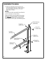
Installation Procedure
Gate Stop
(SP0127)
It is recommended to start installation of
gate from the pivot post and work towards
the receiver post. The gas springs to be
the last items assembled onto the gate.
1. Position pivot post in desired location.
Before anchoring to floor, place gate
stop on top of base plate aligned with
holes along inside edge of base plate,
as shown. Utilize anchors to secure
gate stop in place.
NOTES:
Dimension A to match on page 7.
Refer to the assembly drawing # SP0103
at the end of these instructions to aid in
assembly of the gate.
s
ee
p
a
ge
7
Anchors not provided
by Wildeck, use Ø3/8"
anchors
Pivot Post
(SP0110)

4
Installation Procedure
2. Slide top and bottom rails into pivot post
and secure with clevis pins. Plastic washers
are used between the rails and the post
(both sides of tubes).
NOTES:
The bottom rail with spring attachment bracket
must be oriented as shown below.
Make sure that the top rail closest to the pivot
post does not
have a handle. The top rail with
handle is assembled to the rolling pivot post
at the opposite end of gate, see following steps.
Cotter Pin
(HWM1130)
Bottom Rail
(SP0125)
Plastic Washers
(HWM1480)
Clevis Pin
(HWM1100)
Top Rail
(SP0126)
Clevis Pin
(HWM1100)
Plastic Washers
(HWM1480)
Cotter Pin
(HWM1130)

5
Installation Procedure
3. Install tube insert into bottom of center
tube and then thread on rubber bumper.
Cap other end of tube with plastic plug.
Note orientation of the holes in the center
tube.
4. Attach center plates to center tube.
Secure the top of the plates to the tube
with 1/2" bolt, washers & nut and secure
the bottom of the plates with bolt, washers
and handle grip. Steel washers are used
between the center tube and the center
plates (both sides of tube).
Note orientation of the center plates, the
holes at the top should be at the corners.
5. Attach top and bottom rails to the center
plate assembly secured with clevis pins.
Plastic washers are used between the
rails and the center plates (both sides
of tubes).
NOTE: The orientation of the spring
attachment brackets on the bottom rails are
mirror images of each other.
The top rail with handle must be oriented as
shown below.
Handle
Top Rail w/Handle
(SP0124)
Top Rail
(SP0126)
1/2" x 2-3/4" bolt
(HWB12X275GR5)
Center Plate
(SP0123)
Bottom Rail
(SP0125)
Bottom Rail
(SP0125)
Center Tube
(SP0122)
Tube Insert
(HWF0710)
Rubber Bumper
(HWM1310)
Clevis Pins
(HWM1100)
(4 places)
Handle Grip
(SP0128)
1/2" x 2-3/4" bolt
(HWB12X275GR5)
Center Plate
(SP0123)
Plastic Washers
(HWM1480)
Plastic Plug
(HWF0630)
1/2" Nylock Nut
(HWN12L)
Pivot post (SP0110)
located this end
Steel Washers
(HWW12ST)

6
Installation Procedure
Wheel
(HWM1320)
3/8" x 2-3/4" bolt
(HWB38X275GR5)
3/8" Nylock Nut
(HWN38L)
Plastic Washers
(HWM1480)
Clevis Pin
(HWM1100)
Clevis Pin
(HWM1100)
Top Rail w/Handle
(SP0124)
Cotter Pin
(HWM1130)
Plastic Washers
(HWM1480)
Bottom Rail
(SP0125)
Cotter Pin
(HWM1130)
6. Assemble wheel onto rolling end post
with 3/8" bolt, washers and nut.
NOTE: It may be advantageous to have a
second person help with the following.
7. Slide top and bottom rails into post and
secure with clevis pins. Plastic washers
are used between the rails and the post
(both sides of tubes).
NOTE: The bottom rail with spring
attachment bracket must be oriented as
shown below. It should be a mirror image
of the bottom rail at the other end.
Washers
(HWW38FL)

7
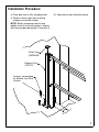
Installation Procedure
Receiver Post
(SP0121)
Plastic Plug
(HWF0640)
Anchors not provided
by Wildeck, use Ø3/8"
anchors
8. Place gate into its fully closed position.
9. Position receiver post next to rolling
end post and anchor to floor.
NOTE: Before anchoring receiver post,
double check that the base plate is aligned
with the pivot post base plate, Dimension A.
10. Cap receiver post with plastic plug.
s
e
e
p
a
g
e
3

Assembled
View
8
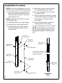
Installation Procedure
NOTE: It may be advantageous to have a
second person help with the following steps.
11. Attach ball studs to spring attachment
brackets on both the bottom rails and
the pivot posts (4 places). Secure the
studs with jam nuts.
NOTE: orientation of ball studs as shown
in Assembled View.
12. Thread ball sockets onto gas springs.
13. Remove clips from the ball sockets.
14. Slide the gate open until it's approx.
6" from fully open to allow room to
install springs.
15. Attach gas springs to ball studs with
the rod pointing down as shown.
16. Secure ball sockets onto studs with
the retaining clips.
17. After the springs are attached, double
check that the springs are aligned with
the centerline of the post, adjust
accordingly.
18. Close and open gate to make sure
nothing binds, fix accordingly.
19. Apply striped tape to rails as desired.
NOTE: below diagrams show attaching
gas springs to rolling pivot post; same
arrangement applies to stationary pivot
post.
Ball Stud
(HWM1050)
Jam Nut
(HWN51618J)
Ball Socket
(HWM1040)
Gas Spring
(HWM1150)
Ball Stud
(HWM1050)
Ball Socket
(HWM1040)
Jam Nut
(HWN51618J)
Retaining Ring
Retaining Ring
Ball Socket
(HWM1040)
Ball Socket
(HWM1040)
Spring must be aligned
with centerline of post
and rails, as shown.

DRN BY: DATE:
REV:
REV
DATE:
JOB #:
QTY:
BRT
3/27/2009
SP0103
Bill of Material
Folding EdgeGard Gate (WG-EFR)
TM
BILL OF MATERIALS
PART #
DESCRIPTIONQTY
ITEM
SP0110
Pivot Post11
SP0120
End Post, Rolling
12
SP0121
Receiver Post13
SP0122Center Post1
4
SP0123Center Connection Plate
2
5
SP0124Top Rail w/ Handle
16
SP0125Bottom Rail2
7
SP0126
Rail Tube18
SP0127Gate Stop19
SP0128Handle with Grip
110
HWM1150
Gas Spring w/M8 Threaded Ends
211
HWM1040
Ball Socket
412
HWM1050
Ball Stud
413
HWN51618JJam Nut, 5/16-18 UNC414
HWB12X275GR5Bolt, 1/2-13 x 2 3/4"
215
HWW12STWasher, 1/2"
4
16
HWN12L
Lock Nut, 1/2-13 UNC
117
HWM1100
Clevis Pin, 1/2" DIA. x 2 1/4" Long
818
HWM1480
Plastic Washer, 1/2" ID x 1 1/4" OD
1619
HWM1130
Cotter Pin, 1/8 x 3/4"
820
HWM1320
Rubber Wheel, 4" Dia.
121
HWB38X275GR5Bolt, 3/8-16 x 2 3/4"
122
HWW38FL
Washer, 3/8"
223
HWN38L
Lock Nut, 3/8-16 UNC
124
HWF0710Tube Insert125
HWM1310Vibration Mount w/ Stud126
HWF0630
Plastic Cap for 1-1/2" Square Tube
127
HWF0640Plastic Cap for 2" Square Tube128
HWM1410
Striped Tape, YELLOW/BLACK
129
6 29
8 29
101516
5
2
21
22
23
24
7
29
729
11121314
9
4
252627
3 28
11
12
13
14
15 16 17
1
5
18 19 20

EdgeGard
™
Dock Gates
WARRANTY
Wildeck EdgeGard™ Dock Gates are warranted to be free of material defects
and workmanship for a period of one (1) year. When properly anchored,
EdgeGard™ Dock Gates are also warranted to meet the 200 lb. OSHA 1910.23 load
force protection requirement.
The warranty begins at time of shipment from Wildeck’s factory. Labor to install,
adjust, maintain or replace the warranted gate, or any component part, is not
included.
This warranty is valid only if the Wildeck EdgeGard™ Dock Gate has been installed
in complete accordance with Wildeck’s Installation Instructions. Improprieties
including but not limited to abuse, negligence, or failure to install, maintain or adjust
the equipment properly, will void the warranty.
The warranty is also voided if unauthorized parts, hardware or equipment are
installed, or modifications are made to the Wildeck EdgeGard™ Dock Gate without
prior written authorization. Wildeck reserves the right to change, at any time, the
material, design or specifications of its products without obligation to subsequent
purchases, or add improvements without making corresponding changes to products
previously manufactured.
WILDECK SHALL NOT IN ANY EVENT BE LIABLE FOR ANY DAMAGES, WHETHER
BASED ON CONTRACT, WARRANTY, NEGLIGENCE, STRICT LIABILITY OR
OTHERWISE, INCLUDING WITHOUT LIMITATION ANY CONSEQUENTIAL,
INCIDENTAL OR SPECIAL DAMAGES, ARISING WITH RESPECT TO THE EQUIPMENT
OR ITS FAILURE TO OPERATE, EVEN IF WILDECK HAS BEEN ADVISED OF THE
POSSIBILITY THEREOF.
WILDECK MAKES NO OTHER WARRANTY OR REPRESENTATION OF ANY KIND,
EXCEPT THAT OF TITLE, AND ALL OTHER WARRANTIES, EXPRESSED OR IMPLIED,
INCLUDING WARRANTIES OR MERCHANTABILITY AND FITNESS FOR A PARTICULAR
PURPOSE, ARE HEREBY EXPRESSLY DISCLAIMED.
Order No._______________________________
P.O. Box 89 • 405 Commerce Street
Waukesha, WI USA 53186
262-549-4000 • 800-325-6939
FAX 262-549-3466 • [email protected]
w
ww.wildeck.com
© Wildeck, Inc. 2011 Printed in USA • WG-EFR-IN 1109
-
 1
1
-
 2
2
-
 3
3
-
 4
4
-
 5
5
-
 6
6
-
 7
7
-
 8
8
-
 9
9
-
 10
10
-
 11
11
-
 12
12


Wildeck EdgeGard Installation Instructions Manual
- Type
- Installation Instructions Manual
Ask a question and I''ll find the answer in the document
Finding information in a document is now easier with AI
Other documents
-
Crain 1500-23 Owner's manual
-
Kohler K-9669-BN Installation guide
-
 MACGREGOR 26 M Owner's Instructions Manual
-
Gilson Gilso-Matic Screening Assembly User manual
-
Meyer Front and Rear Unload Forage Boxes with Indpendent Outfeed Clutch User manual
-
Ventrac SS575 Owner's manual
-
Chrysler Dodge Monaco 1966 User manual
-
 Bruno VPL-3100 Installation guide
-
Ransomes 70411, 70414 Owner's manual
-
Christie Digital Systems P35GPS-AT User manual

