6 31-2000792 Rev. 0
Instrucciones de Instalación
8
CÓMO REVISAR LAS LLAMAS DE
LOS QUEMADORES A GAS
NATURAL
El horno viene ajustado de fábrica para ser usado con gas
natural en la mayoría de las áreas. Pero, como el gas en
algunas áreas varía, usted debe revisar todos los ajustes que
se describen más abajo. Si usted va a usar gas LP, mire los
Ajustes para Gas LP en la parte final de esta guía.
NOTA: La llama para hornear y asar a la parrilla debe ser
revisada con la puerta cerrada para revisar adecuadamente
las características de la llama. Para revisar correctamente el
quemador para hornear, el fondo del horno y el esparcidor de
llamas deben ser removidos.
Encienda el quemador para hornear o asar.
Mientras mire la llama con la puerta del horno cerrada,
revise lo siguiente a través de la ventana de la puerta:
1. Las llamas del quemador no deberían pestañear o
soplar en dirección opuesta al quemador.
2. Deberían ser de color azul sin muestras de amarillo.
3.(OFRQRLQWHULRUGHODOODPDGHEHUtDVHUGHƎDƎ
de longitud.
LOS QUEMADORES DEBERÍAN SER REVISADOS
FRECUENTEMENTE.
9
CÓMO AJUSTAR LAS LLAMAS DEL
QUEMADOR (Cont.)
E. Use un destornillador para soltar el tornillo del obturador
de aire.
1. Si las llamas estaban amarillas, abra el obturador más
que la posición original.
2. Si las llamas soplaban en dirección opuesta al
quemador, cierre el obturador más que la posición
original.
F. Haga el ajuste.
G. Apriete nuevamente el tornillo del obturador.
H. Cierre la puerta y revise nuevamente la llama.
Cuando los resultados son satisfactorios:
1. Coloque nuevamente la cubierta del orificio.
2. Coloque el esparcidor de llamas en su lugar.
3. Coloque nuevamente el fondo del horno.
QUEMADOR PARA ASAR
A. El quemador para asar está ubicado y es accessible en la
parte superior trasera del horno.
B. Use un destornillador para soltar el tornillo de ajuste del
obturador.
1. Controle el obturador de aire para asegurar que se
encuentre en la posición completamente abierta y
libre de cualquier obstrucción. Para la aplicación NG,
asegúrese de que el regulador se encuentre en la
posición NG. Para las aplicaciones de LP, asegúrese
de que la campana se haya ajustado en la posición LP.
2. Si las llamas soplaban en dirección opuesta al
quemador, cierre el obturador más que la posición
original.
C. Haga el ajuste.
D. Apriete nuevamente el tornillo del obturador.
E. Cierre la puerta del horno y revise nuevamente la llama.
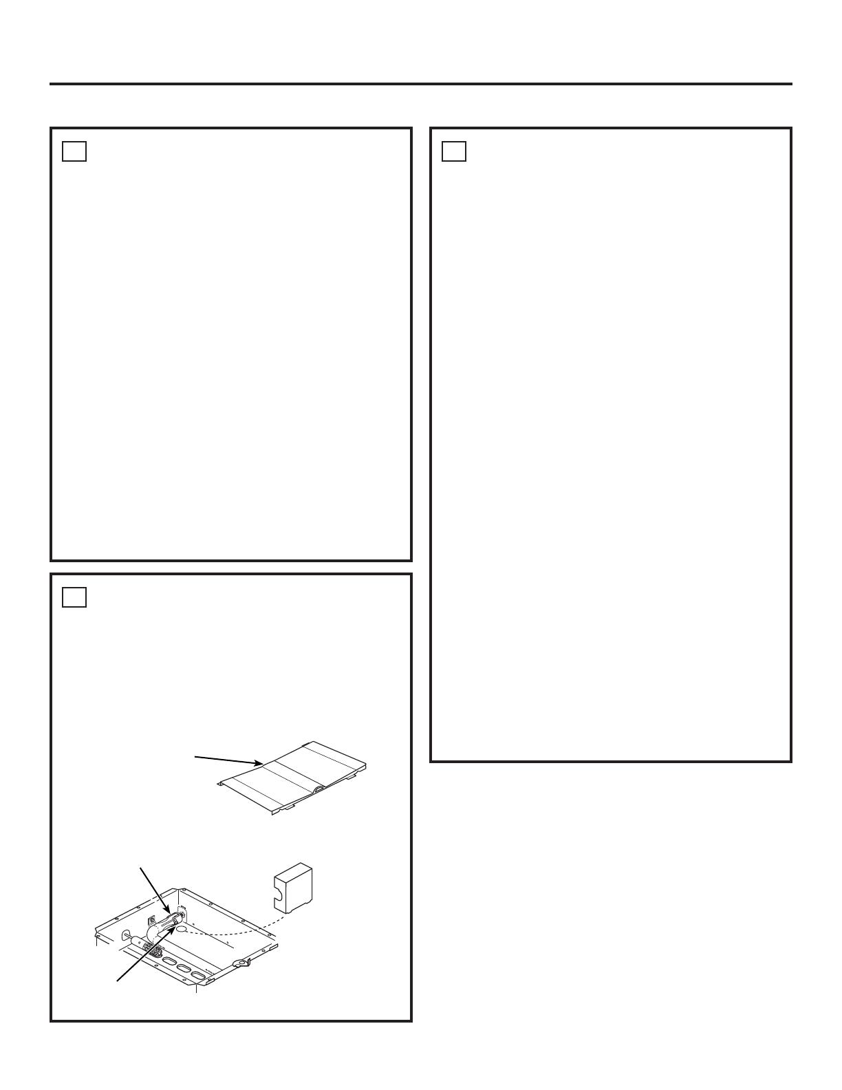
9
CÓMO AJUSTAR LAS LLAMAS DEL
QUEMADOR
QUEMADOR DEL HORNEAR
A. Abra la puerta del horno.
B. Saque el fondo del horno.
C. Saque los 4 tornillos para remover el esparcidor de
llamas..
D. Saque la cubierta del orificio.
INSTALACIÓN DEL HORNO (Cont.)
Esparcidor del
quemador fondo
del horno
Fig. 9
Obturador de Aire
Cubierta
del Orificio
Tornillo del
Obturador de Aire
Fig. 10


