Multi-Tech Systems BL-Series User manual
- Category
- Networking
- Type
- User manual

BL-Series
Intelligent Data/Fax Modem
User Guide

User Guide
88312100 Revision A
MultiModem
II
Models:
MT2834BL/MT2834BLI/MT2834BLK
MT1932BL/MT1932BLI/MT1932BL-Mac
MT1432BL/MT1432BLI/MT1432BLK
This publication may not be reproduced, in whole or in part, without prior expressed written
permission from Multi-Tech Systems, Inc.
All rights reserved.
Copyright 1999 ©, by Multi-Tech Systems, Inc.
Multi-Tech Systems, Inc. makes no representations or warranties with respect to the contents hereof
and specifically disclaims any implied warranties of merchantability or fitness for any particular
purpose. Furthermore, Multi-Tech Systems, Inc. reserves the right to revise this publication and to
make changes from time to time in the content hereof without obligation of Multi-Tech Systems, Inc.
to notify any person or organization of such revisions or changes.
Record of Revisions
A (6/1/99) Manual formatted for electronic distribution. All pages at Revision A.
Trademarks of Multi-Tech Systems, Inc. are as follows:
MultiModem
II
, Multi-Tech and the Multi-Tech logo.
MNP, Microcom Network Protocol is a trademark of Microcom Inc.
AS/400 and System3x is a trademark of IBM.
Macintosh is a trademark of Apple Computer Inc.
Unix is a trademark of X/Open Co. Ltd.
Windows® and Windows® 95 are registered trademarks of Microsoft
All other brands and product names mentioned in this publication are trademarks or registered
trademarks of their respective companies.
Multi-Tech Systems, Inc.
2205 Woodale Drive
Mounds View, Minnesota 55112 U.S.A.
(612) 785-3500 or (800) 328-9717
U. S. FAX 612-785-9874
Fax-Back Service 612-717-5888
Technical Support (800) 972-2439
BBS (612) 785-3702 or (800) 392-2432
Internet Address: http://www.multitech.com
Technical Writer: [email protected]

Contents
Chapter 1 - Introduction and Description
1.1 Introduction...................................................................................................................................... 8
1.2 How To Use This Manual................................................................................................................. 8
1.3 Modem Features ............................................................................................................................. 10
1.3.1 2834 Series Features................................................................................................................ 10
1.3.2 1932 Series Features................................................................................................................ 10
1.3.3 1432 Series Features................................................................................................................ 11
1.4 Fax Features ................................................................................................................................... 11
1.5 Technical Specifications .................................................................................................................. 12
1.6 Power .............................................................................................................................................. 16
1.7 Modem LED Indicators.................................................................................................................... 16
1.8 Controls on PC Board ..................................................................................................................... 17
Chapter 2 - Installation and Connection
2.1 What is in Your Modem Package? .................................................................................................. 20
2.2 Installation ....................................................................................................................................... 21
2.2.1 Safety Warnings........................................................................................................................ 21
2.2.2 Installation Procedure ............................................................................................................... 21
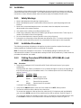
2.2.3 Cabling Procedure (MT1432BL/BLI, MT1932BL/BLI, and MT2834BL/BLI) .............................. 21
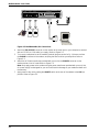
2.2.4 Cabling Procedure (MT1432BLK and MT2834BLK) ................................................................. 23
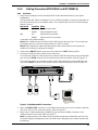
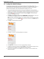
2.3 Loading Trio DataFAX Software ...................................................................................................... 24
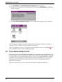
2.4 Is Your Modem Ready for Use? ...................................................................................................... 26
Chapter 3 - Software Configuration and Modem Basics
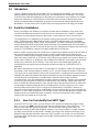
3.1 Introduction...................................................................................................................................... 28
3.2 Serial Port Limitations ..................................................................................................................... 28
3.2.1 How Can You Identify Your UART Type? .................................................................................. 28
3.2.2 The 16550 UART and Windows 3.1.......................................................................................... 29
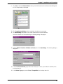
3.3 Configuring Your Software............................................................................................................... 29
3.3.1 ConfiguringSoftware for Your Modem ....................................................................................... 29
3.4 PC Initialization Strings ................................................................................................................... 30
3.4.1 Changing Default Parameters................................................................................................... 30
3.4.2 Other Parameters ..................................................................................................................... 30
3.5 Macintosh Initialization .................................................................................................................... 31
3.6 Configuring Software for Your Computer......................................................................................... 31
3.6.1 Configuring Software for the Remote System........................................................................... 31
3.6.2 Terminal Emulation ................................................................................................................... 31
3.6.3 File Transfer Protocols .............................................................................................................. 32
3.7 When to Disable Data Compression ............................................................................................... 32
3.7.1 Disabling Error Correction......................................................................................................... 32
3.8 Modem Basics................................................................................................................................. 33
3.8.1 Simple Operations .................................................................................................................... 33
3.9 The Answer/Originate - Voice/Data Toggle Switch .......................................................................... 33
iii

Chapter 4 - Manual Dial and Automatic Answer
4.1 Introduction...................................................................................................................................... 36
4.2 Dialing/On-Line/Answering .............................................................................................................. 36
4.3 Automatic Leased Line Restoral Operation.....................................................................................37
4.4 Manual Dial Backup Call Termination.............................................................................................. 37
4.5 Dial Backup and Leased Line Restoral ........................................................................................... 37
4.6 Dial-Up Operation............................................................................................................................ 38
4.7 Manual Call Origination ................................................................................................................... 38
4.8 Automatic Answering ....................................................................................................................... 39
4.9 Manual Answering ........................................................................................................................... 39
4.10 Handshaking Details ....................................................................................................................... 40
4.11 Call Termination ............................................................................................................................... 40
Chapter 5 - Command Mode
5.1 Introduction...................................................................................................................................... 42
5.1.1 AT Command Editing ................................................................................................................ 42
5.1.2 Functional Modes...................................................................................................................... 43
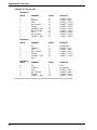
5.2 Summary of AT Commands............................................................................................................. 44
5.3 Result Codes................................................................................................................................... 47
5.4 Dialing Commands .......................................................................................................................... 49
5.4.1 Dialing Action Commands ......................................................................................................... 49
5.4.2 Dial Modifier Commands........................................................................................................... 50
5.4.3 Phone Number Memory Commands......................................................................................... 53
5.4.4 Configuration and Default Storage Commands ........................................................................ 54
5.4.5 Command Response (Result Code) Commands...................................................................... 56
5.4.6 Phone Line Conditioning Commands........................................................................................ 58
5.4.7 RS-232C Interface Control Commands .................................................................................... 61
5.4.8 Error Correction Commands ..................................................................................................... 63
5.4.9 Flow Control Commands .......................................................................................................... 66
5.4.10 Compression, Error Correction, Flow Control, Pass-Through and Pacing Commands ............ 69
5.4.11 Speed Conversion Commands .................................................................................................70
5.4.12 Immediate Action Commands ................................................................................................... 73
5.4.13 Line Probe Commands (2834 Series only) ............................................................................... 75
Chapter 6 - S-Registers
6.1 Introduction...................................................................................................................................... 78
6.2 Reading and Assigning S-Register Values ......................................................................................85
6.2.1 Examples of Assigning Values .................................................................................................. 85
6.2.2 Examples of Reading Values .................................................................................................... 85
6.3 AT Command and S-Register Summary ......................................................................................... 86
Chapter 7 - Callback Security and Remote Configuration
7.1 Introduction...................................................................................................................................... 88
7.2 Callback Feature Description .......................................................................................................... 88
7.3 Remote Configuration Description................................................................................................... 89
7.3.1 Initial Setup Procedures for Callback and Remote Configuration. ............................................ 89
7.3.2 Remote Configuration Procedures............................................................................................92
7.4 Remote Configuration and Callback Security AT Commands ......................................................... 93
7.5 Remote Configuration/Callback Security S-Registers ..................................................................... 95
iv

Chapter 8 - Modem Testing
8.1 Introduction...................................................................................................................................... 98
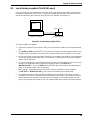
8.2 Local Analog Loopback Test/V.54 Loop 3........................................................................................ 99
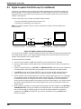
8.3 Digital Loopback Test/V.54 Loop 2 (Local/Manual).......................................................................... 100
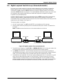
8.4 Digital Loopback Test/V.54 Loop 2 (Remote/Automatic) ................................................................. 101
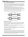
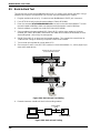
8.5 Back-to-Back Test ........................................................................................................................... 102
8.6 Synchronous Mode Testing ............................................................................................................. 103
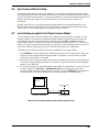
8.7 Local Analog Loopback Test (Synchronous Mode) ......................................................................... 103
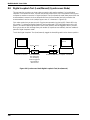
8.8 Digital Loopback Test (Local/Manual) (Synchronous Mode) ........................................................... 104
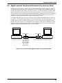
8.9 Digital Loopback Test (Remote/Automatic) (Synchronous Mode) ................................................... 105
Chapter 9 - DIP-Switch Settings
9.1 Introduction...................................................................................................................................... 108
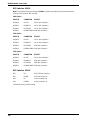
9.2 DIP-Switch Option Settings ............................................................................................................. 109
9.3 Speaker Volume Control ................................................................................................................. 114
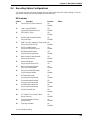
9.4 Recording Option Configurations .................................................................................................... 115
Chapter 10 - Warranty, Service and Tech Support
10.1 Introduction...................................................................................................................................... 118
10.2 Limited Warranty ............................................................................................................................. 118
10.2.1 On-line Warranty Registration................................................................................................... 118
10.3 Tech Support ................................................................................................................................... 119
10.3.1 Recording Modem Information.................................................................................................. 119
10.4 Service ............................................................................................................................................ 119
10.5 The Multi-Tech BBS......................................................................................................................... 120
10.5.2 Upgrading the MultiModem ...................................................................................................... 121
10.5.3 Using FlashPro to Upgrade Modem Firmware.......................................................................... 121
10.6 About Multi-Tech’s Internet Presence.............................................................................................. 121
10.7 About the Multi-Tech Fax-Back Service .......................................................................................... 121
10.8 About Ordering Accessories............................................................................................................ 122
Appendixes
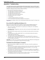
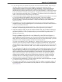
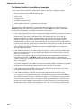
Appendix A - Troubleshooting....................................................................................................................... 124
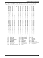
Appendix B - ASCII Character Code/Hex/Decimal Conversion Chart .......................................................... 129
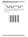
Appendix C - Dial Pulse and Tone-Dial Frequencies.................................................................................... 130
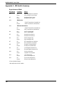
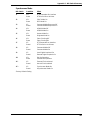
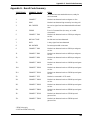
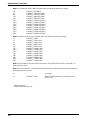
Appendix D - Command Summary............................................................................................................... 131
Appendix E - DIP-Switch Summary ............................................................................................................. 140
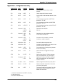
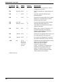
Appendix F - S-Register Summary .............................................................................................................. 143
Appendix G - Result Code Summary ........................................................................................................... 145
Appendix H - V.25bis Operation ................................................................................................................... 147
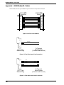
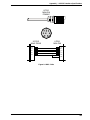
Appendix I - MultiModemBL Cables ............................................................................................................. 154
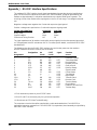
Appendix J - RS-232C Interface Specifications ........................................................................................... 156
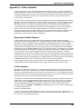
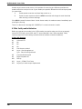
Appendix K - Regulatory Information ........................................................................................................... 160
Index
v

vi

Chapter 1 - Introduction and Description

8
MultiModemBL User Guide
1.1 Introduction
Welcome to the world of data communications. You have acquired one of the finest intelligent
desktop data/fax modems available today, the MultiModem
II
BL series modem, from Multi-Tech
Systems. This User Guide covers various models within the BL series, and unless otherwise noted,
all content should be considered relevant to all models.
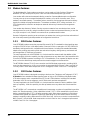
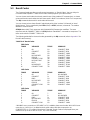
Your MultiModem provides data communication at the following rates:
Model
MT2834BL Series
MT1932BL Series
MT1432BL Series
Baud Rate
33,600 - 14,400 bps (*Enhanced V.34/V.32bis)
19,200 - 14,400 bps (V.32terbo/V.32bis)
14,400 - 300 bps (V.32bis)
*Note enhancements on V.34 code (33.6K/31.2K) is awaiting formal ITU approval; the ITU study group 14 has agreed on
the technical side of the proposal, with formal approval expected at the next ITU meeting in Geneva.
The MultiModem also provides other prevalent data communications standards and includes dial
backup with automatic lease line restoration, adaptive protocol enhancing used in typical Unix® batch
file transfers and support for IBM's AS/400
TM
and Windows
TM
environments.
1.2 How To Use This Manual
This manual is divided into ten chapters. While viewing in Acrobat ReaderTM you can click on blue
text to jump to the section of the manual it references. Red, bold text indicates a hyperlink to the
Internet. If you have a Web browser active on your system, click on these text links to open the
browser and go to the referenced site. The information contained in each chapter and appendix is as
follows:
Chapter 1 - Introduction and Description
This chapter begins with a short introduction, followed by a guide (which you are now reading) to the
use of this manual. There is a discussion about what components you can expect in your modem
package. We then provide a more detailed description of the modem, including the modem’s
technical specifications. Chapter 1 includes sections covering power, LED indicators and a brief
summary of PC board controls. (Chapter 9 covers switch settings more thoroughly.)
Chapter 2 - Installation and Connection
Chapter 2 covers the procedure for connecting the modem to your computer and to the phone line.
Details are given, supported by illustrations on the modem's back panel connections as a guide to
install your modem to the point of operation. In addition, this chapter guides you through the
installation of Trio, the communications software included with your modem.
Chapter 3 - Software Configuration and Modem Basics
Chapter 3 documents communication software configuration recommended specifically for the
MultiModem. Other issues covered include setting up initialization strings, changing default
parameters, configuring software for the remote system and file transfer protocols.
Chapter 4 - Manual Dial and Automatic Answer
Chapter 4 covers some modem operations, but delays discussion on Command Mode operation until
Chapter 5. Automatic Leased Line Restoration, Dial backup, Manual Dial Mode, and Answer Mode
operation are covered in detail, as well as the handshaking procedures employed between two
modems in an auto-answer application.

9
Chapter 1 - Introduction and Description
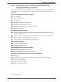
Chapter 5 - AT Command Mode Operation
Chapter 5 may be the most important chapter of this manual. It begins with an introduction and
discussion on Command Mode fundamentals. A flow chart is provided to illustrate Command Mode
and On-Line Mode operation and the methods used in each mode. Next, there is a summary of the
modem’s commands and responses. We then go into a detailed explanation of each modem
command, providing examples where applicable.
Chapter 6 - S-Registers
Chapter 6 covers the modem's S-Registers, which enable the user to establish, read, and modify
various modem options. All of the S-Registers are charted and explained, followed by instructions on
accessing the S-Registers and reading or changing their values.
Chapter 7 - Callback and Remote Configuration
Chapter 7 documents instructions on how to operate the modem's Callback and Remote
Configuration features; and the usage of LOGIN Passwords, Set-Up Passwords and Remote Escape
Characters as network management tools.
Chapter 8 - Testing Your Modem
Chapter 8 covers the modem's built-in test features. These are: Power-on Self Test, Back-To-Back
Test, Local Analog Loopback, Digital Loopback and Remote Digital Loopback Tests. We have
included a description of each test and how to use each test procedure.
Chapter 9 - DIP-Switches
Chapter 9 covers the modem’s printed-circuit board options. Sixteen DIP-Switch settings and the
modem's speaker volume control are explained in detail, including all default settings.
Chapter 10 - Warranty, Service & Technical Support
Chapter 10 provides statements on your five-year warranty, instructions for getting modems serviced
at the factory, the procedure for downloading firmware upgrades via FlashROM, information about
Multi-Tech's Bulletin Board Service (BBS), a section on receiving technical support via the
CompuServe/Internet forums and information on Multi-Tech's Fax-Back Service.
Appendixes
There are also several appendices at the end of this manual, most of which repeat information
contained in the chapters, but in a more condensed form. These appendices can be used as a quick
reference.
Appendix A - Troubleshooting
Appendix B - ASCII/HEX/Decimal Conversion Chart
Appendix C - Pulse Dial and Tone-Dial Frequencies
Appendix D - AT Command Summary
Appendix E - DIP Switch Summary
Appendix F - S-Register Summary
Appendix G - Result Code Summary
Appendix H - V.25bis Operation
Appendix I - Cabling Diagrams
Appendix J - RS-232 Interface Specifications
Appendix K - Regulatory Information

10
MultiModemBL User Guide
1.3 Modem Features
The MultiModem BL Series modem connections can be made on Public Switched Telephone
Networks (PSTNs) and/or point-to-point 2-wire and 4-wire leased telephone type circuits.
Your modem offers interactive automatic dialing, as well as Command Mode option configuration.
You may store up to ten command line/telephone numbers, of up to 60 characters each, in the
modem’s nonvolatile memory. The modem pulse or tone dials, and recognizes dial tones and busy
signals for reliable call-progress detection. The modem can detect AT&T calling card tones. It is
FCC-Registered for connection to telephone networks without any Data Access Arrangements
(DAA’s).
Your modem also features Callback Security to protect networks from unauthorized use, and to
manage phone line costs. By using the modem’s phone number and password directory, a host site
can, upon receipt of a call, callback to a remote site at a predetermined number.
Remote Configuration permits you to assist users at remote sites, saving you the time and trouble of
site visits and preventing misinterpretation of configuration instructions.
1.3.1 2834 Series Features
Your MT2834BL modem meets the proposed Enhanced V.34 ITU standard for data signalling rates
as high as 33.6/31.2K bps in full duplex mode. Enhanced V.34 is an extension of V.32/V.32bis/V34
standards, and supports and is compatible with those features, including EIA extended Automode;
adaptive line probing; automatic symbol rate and carrier frequency during start-up; and retrain and
rate renegotiation (in 2400 bps increments).
The major application for the MT2834BL is in 4-wire leased line networks with the addition of dial
backup capability. With this capability, the dial-up feature saves any down time if the leased line fails.
Since the MT2834BL operates according to ITU V.34 modulation, it can operate full-duplex over two
wires, so that the dial backup mode performs the same throughput as the leased line.
The MT2834BL features ITU V.42 error correction and V.42bis data compression, providing 100%
error-free data transmission. V.42 error correction incorporates MNP( Classes 3 and 4, and LAP-M.
You may select V.42bis data compression for 4-1 throughput, or MNP Class 5 for 2-1 throughput.)
1.3.2 1932 Series Features
Your MT1932BL modem is designed according to the American Telephone and Telegraph (AT & T)
V.32terbo de facto standard for data signalling rates as high as 19.2/16.8K bps full-duplex mode.
V.32 terbo supports and is compatible with all V.32 and V.32bis features including EIA extended
Automode, the V.32 start-up sequence, and V.32bis retrain and rate renegotiation.
The major application for the MT1932BL is in 4-wire leased line networks with the addition of dial
back-up capability. With this capability, the dial-up feature saves any down time if the leased line
fails.
The MT1932BL is AT command set compatible and incorporates a number of capabilities beyond the
basics of V.32terbo operation. Other capabilities include CCITT V.25bis standard for synchronous
dialing, compatibility with CCITT V.42 error correction and V.42bis data compression in which data
communication speeds can approach 78,600 bps (depending on the file content and the receiving
modem’s capability) and the data sent will be 100% error free. V.42 error correction incorporates both
MNP Classes 3, 4 and LAPM. Data compression can be V.42bis for 4 to 1 throughput improvement
or MNP Class 5 for 2 to 1 throughput.

11
Chapter 1 - Introduction and Description
1.3.3 1432 Series Features
Your MT1432BL modem is designed according to the international CCITT V.32bis specification for
data signalling rates as high as 14.4K bps in full-duplex mode.
The major application for the MT1432BL is in 4-wire leased line networks (replacing traditional V.29/
9600 bps & V.33/14,400 bps modems) with the addition of dialback-up capability. With this
capability, the dial-up feature saves any down time if the leased line fails. Since the MT1432BL
operates according to CCITT V.32bis modulation, it can operate full-duplex over two wires, so that
the dial back-up mode performs the same throughput as the leased line.
The MT1432BL is AT command set compatible and incorporates a number of capabilities beyond the
basics of V.32bis operation. Other capabilities include CCITT V.25bis synchronous dialing,
compatibility with CCITT V.42 error correction and V.42bis data compression in which data
communication speeds approach 57,600 bps (depending on the file content and the receiving
modem’s capability) and the data sent will be 100% error free.
1.4 Fax Features
Your modem meets the ITU V.17 standard for sending and receiving faxes. When linked to a
compatible fax machine or modem, it can transmit faxes at 14,4 K bps. It also meets the ITU’s Group
3 Designation for sending and receiving faxes at 9600 bps; and Group 2 Designation for sending and
receiving faxes at 4800 bps. The modem is also downward-compatible with modems to speeds as
low as 300 bps, so it can send and receive faxes with any fax machine in the world.

12
MultiModemBL User Guide
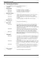
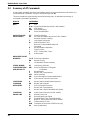
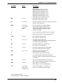
1.5 Technical Specifications
Your data/fax modem meets the specifications listed below:
Tradename MultiModem
IITM
Model Numbers
2834 Series: MT2834BL, MT2834BLI, MT2834BLK
1932 Series: MT1932BL, MT1932BLI, MT2834BL-MAC
1432 Series: MT1432BL, MT1432BLI, MT21432BLK
Data Rates (modem)
2834 Series: 33,600, 31,200, 28,800, 26,400, 24,000, 21,600, 19,200, 16,800,
14,400, 12,000, 9600, 7200, 4800, 2400, 1200, 0-300 bps
1932 Series: 19,200, 16,800, 14,400, 12,000, 9600, 7200, 4800, 2400, 1200,
0-300 bps
1432 Series: 14,400, 12,000, 9600, 7200, 4800, 2400, 1200, 0-300 bps
Data Rates (fax)
All Models: 14,400, 9600, 7200, 4800 bps
Data Format
2834 Series: Serial, binary, asynchronous at 0-300, 1200, 2400, 4800, 7200,
9600, 12,000, 14,400, 16,800, 19,200, 21,600, 24,000, 26,400,
28,800, 31,200, 33,600 bps; synchronous at 1200, 2400, 4800,
7200, 9600, 12,000, 14,400, 16,800, 19,200, 21,600, 24,000, 26,400,
28,800, 31,200, 33,600 bps
1932 Series: Serial, binary, asynchronous at 0-300, 1200, 2400, 4800, 7200,
9600, 12,000, 14,400, 16,800, 19,200 bps; synchronous at 1200,
2400, 4800, 7200, 9600, 12,000, 14,400, 16,800, 19,200 bps
1432 Series: Serial, binary, asynchronous at 0-300, 1200, 2400, 4800, 7200,
9600, 12,000, 14,400 bps; synchronous at 1200, 2400, 4800, 7200,
9600, 12,000, 14,400 bps
Compatibility
2834 Series: ITU V.42bis, V.42, Pending ITU Enhanced V.34 approval, ITU V.34,
ITU V.32bis, V.32, V.21*, V.22bis, V.22, V.23*,V.25bis, *Bell 212A
and 103/113, ITU V.17, Group 3 T.4, T.30 and EIA TR-29 Class 2
(*Bell 212A and 103/113 domestic models only; *V.21/V.23 Int'l
models only)
1932 Series: CCITT V.42bis, V.42, AT&T V.32terbo, CCITT V.32bis, V.32, V.21*,
V.22bis, V.22, V.23*, V.25bis, Bell 212A and 103/113, CCITT V.17,
Group 3 T.4, T.30 and EIA TR-29 Class 2 (* V.21/V.23 Int’l models
only)
1432 Series: CCITT V.42bis, V.42, CCITT V.32bis, V.32, V.21*, V.22bis, V.22,
V.23*, V.25bis, Bell 212A and 103/113*, CCITT V.17, Group 3 T.4,
T.30 adn EIA TR-29 Class 2 (* Bell 212A and 103/113 domestic
models only; * V.21/V.23 Int’l models only)
Error Correction
All models: V.42 (LAP-M or MNP 3 & 4) error correction

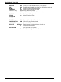
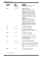
13
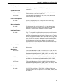
Chapter 1 - Introduction and Description
Data Compression
All models: V.42bis, (4:1 throughput) or MNP 5 (2:1 throughput) data
compression
Speed Conversion
2834 and 1932 Series: Serial port data rates adjustable to 300, 1200, 2400, 4800, 9600,
19,200, 38,400, 57,600 and 115,200 bps
1432 Series: Serial port data rates adjustable to 300, 1200, 2400, 4800, 9600,
19,200, 38,400, and 57,600 bps
Flow Control Options
All models: Xon/Xoff, Hardware RTS/CTS, ENQ/ACK, Unix-to-Unix Copy
Protocol (UUCP) "Spoofing"
Mode of Operation
All models: Full duplex over both dial-up lines and 2- or 4-wire leased lines;
automatic Dial backup on separate lines in leased line operation;
automatic or manual dialing, automatic or manual answer
Intelligent Features
All models: Fully “AT command” compatible, microprocessor controlled remote
configuration, EIA extended Automode, adaptive line probing,
automatic symbol rate and carrier frequency during start-up, retrain
and rate renegotiation, autodial, redial, repeat dial, dial linking, pulse
or tone dial, dial tone detection, dial pauses, call status display, auto-
parity and data rate selection, keyboard-controlled modem options,
nonvolatile memory and on-screen displays for modem option
parameters and up to ten telephone numbers/command lines of up
to 60 digits each, help menus
Command Buffer
All models: 60 characters
Modulation
2834 Series: Trellis Coded Modulation (TCM) at 33,600, 31,200, 28,800, 26,400,
24,000, 21,600, 19,200, 16,800, 14,400, 12,000 and 9600 bps,
Quadrature Amplitude Modulation (QAM) at 9600 (non-trellis), 4800
and 2400 bps, PSK at 1200 bps, FSK at 300 bps
1932 Series: Trellis Coded Modulation (TCM) at 19,200, 16,800, 14,400, 12,000
and 9600 bps, Quadrature Amplitude Modulation (QAM) at 9600
(non-trellis), 4800 and 2400 bps, PSK at 1200 bps, FSK at 300 bps
1432 Series: Trellis Coded Modulation (TCM) at 14,400, 12,000 and 9600 bps,
Quadrature Amplitude Modulation (QAM) at 9600 (non-trellis), 4800
and 2400 bps, PSK at 1200 bps, FSK at 300 bps
Fax Modulations
All models: V.21CH2 FSK at 300 bps, V.27ter DPSK at 4800 and 2400 bps,
V.29 QAM at 9600 and 7200 bps, V.17 TCM at 14400, 12000, 9600,
and 7200 bps

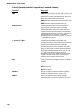
14
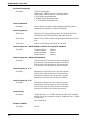
MultiModemBL User Guide
Fax Carrier Frequencies
All models: V.21CH2 (Half Duplex)
1650Hz Mark, 1850Hz Space for Transmit Originate
1650Hz Mark, 1850Hz Space for Transmit Answer
V.27ter 1800Hz Originate/Answer
V.29 QAM 1700Hz Originate/Answer
V.17 TCM 1800Hz Originate/Answer
Lease Line Restoral
All models: When in dial backup mode, modem attempts leased line restoral
periodically (controlled by S-Register S18 setting)
Carrier Frequencies
2834 Series: 1800 Hz V.32/V.32bis/V.34/Enhanced V.34--33.6K/31.2K/28.8K/
26.4K/24K/21.6K/19.2K/16.8K/14.4K/12K/9.6K/7.2K/4.8K
1932 Series: 1800 Hz V.32/V.32bis/V.32terbo/19.2K/16.8K/14.4K/12K/9.6K/7.2K/
4.8K
1432 Series: 1800 Hz V.32/V.32bis/14.4K/12K/9.6K/7.2K/4.8K
Carrier Frequencies - 2400 & 1200 bps (V.22bis/V.22 or Bell 212A Standard)
All models: Transmit Originate: 1200 Hz
Transmit Answer: 2400 Hz
Receive Originate: 2400 Hz
Receive Answer: 1200 Hz
Carrier Frequencies - 300 bps (Bell Standard)
All models: 1270 Hz Mark, 1070 Hz Space for Transmit Originate
2225 Hz Mark, 2025 Hz Space for Receive Originate
2225 Hz Mark, 2025 Hz Space for Transmit Answer
1270 Hz Mark, 1070 Hz Space for Receive Answer
Carrier Frequencies - V.21
All models: 980 Hz Mark, 1180 Hz Space for Transmit Originate
1650 Hz Mark, 1850 Hz Space for Transmit Answer
650 Hz Mark, 1850 Hz Space for Receive Originate
980 Hz Mark, 1180 Hz Space for Receive Answer
Carrier Frequencies - V.23
All models: 390 Hz Mark, 450 Hz Space for Transmit Originate
1300 Hz Mark, 2100 Hz Space for Transmit Answer
1300 Hz Mark, 2100 Hz Space for Receive Originate
390 Hz Mark, 450 Hz Space for Receive Answer
Transmit Level
All models: -11dBm (dial-up), -9 or -15 dBm (leased-line); dBm level selectable
with DIP-Switch #3 in leased line setting; -10dBm (dial-up)*, -13 dBm
(leased-line)*
*BLK models Only
Frequency Stability
All models: ±0.01%

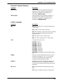
15
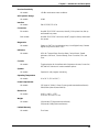
Chapter 1 - Introduction and Description
Receiver Sensitivity
All models: -43 dBm under worst case conditions
AGC Dynamic Range
All models: 43 dB
Interface
All models: EIA RS-232C/ITU V.24
Connectors
BL models: One DB-25 RS-232C connector; three RJ11 for phone line, dial-up
and leased line; power.
BLK models: One DB-25 RS-232C connector; two BT plugs for dial-up and leased
line; power
Diagnostics
All models: Power-on Self Test, Local Analog Loop, Local Digital Loop, Remote
Digital Loop, Back-to-Back Test.
Indicators
All models: LEDs for Transmit Data, Receive Data, Carrier Detect, Speed
Indicators, Off Hook, Terminal Ready, Error Correction, Fax, and
Error
Controls
All models: Toggle switches for Voice/Data with Originate or Answer, Power On/
Off; and DIP Switches for various modem options.
Speaker
All models: Speaker for call progress monitoring
Operating Temperature
All models: 0° to 50° C (32° to 120° F)
Power Requirements
All models: 115 Volts AC, 60Hz, 0.3amp (2-prong outlet-mounted transformer)
240V/50Hz optional (International).
Dimensions
All models: 6.150" x 9.00" x 1.375"
15.6 cm x 22.9 cm x 3.5 cm
Weight
All models: 1.6 pounds/0.72 Kg (without transformer)
2.6 pounds/1.18Kg (with transformer)
Limited Warranty
All models: Five Years

16
MultiModemBL User Guide
1.6 Power
Power is supplied through an AC power transformer terminated with a standard two-prong plug. The
transformer supplies low voltage AC to the modem, and plugs into any conventional 115 volt AC, 60
Hz, two-prong power outlet (240 volts AC, 50Hz, .3 Amp for International modems). The power
transformer supplied with the modem is the only one that should be used. Use of any other
transformer could cause damage to the modem. A Power On/Off switch is located on the back of the
modem.
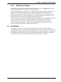
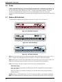
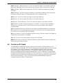
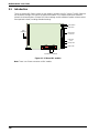
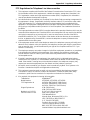
1.7 Modem LED Indicators
The MultiModem diagnostic LED indicators are shown in Figures 1-1a, 1-1b, and 1-1c.
Figure 1-1a. MT2834 LED Display
Figure 1-1b. 1932 LED Display
Figure 1-1c. MT1432 LED Display
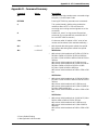
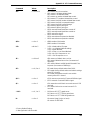
(SD) Send (Transmit) Data. This LED blinks when data is being transmitted, on for a space, off for a
mark. The state of this LED matches the TD circuit on Pin 2 of the RS-232C/V.24 interface.
(RD) Receive Data. This LED blinks when data is being received, on for a space, off for a mark. The
state of this LED matches that of the RD circuit on Pin 3 of the RS-232C/V.24 interface.
(CD) Carrier Detect. This LED is lit when a valid carrier tone has been detected.
2834 Models Only:
When the modem is connected at 33,600 bps, the 28.8 LED rapidly blinks at approximately 5
blinks per second.
When the modem is connected at 31,200 bps, the 28.8 LED blinks slowly at approximately 1
blink per second.
(28.8) 28,800 bps. (2834 models only) This LED is lit when the modem is connected at 28,800 bps.
Note: if the modem falls back to 26.4K bps while in V.34 mode, both the 28.8 and 24.0 LEDs light.

17
Chapter 1 - Introduction and Description
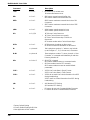
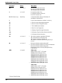
(24.0) 24,000 bps. (2834 models only). This LED is lit when the modem is connected at 24,000 bps.
Note: if the modem falls back to 21.6K bps while in V.34 mode, both the 24.0 and 19.2 LEDs light.
(19.2) 19,200 bps. (2834 and 1932 models only) This LED is lit when the modem is connected at
19,200 bps.
(14.4) 14,400 bps. This LED is lit when the modem is connected at 14,400 bps. Note: if the modem
falls back to 12,000 bps while in V.32bis mode, both the 14.4 and 96 LEDs light.
(96) 9600 bps. This LED is lit when the modem is connected at 9600 bps.
(24) 2400 bps. This LED is lit when the modem is connected at 2400 bps.
(12) 1200 bps. (1432 models only) This LED is lit when the modem is connected at 1200 bps.
(OH) Off Hook. This LED is lit when the phone line is "off hook". This occurs when the modem is
dialing, on-line, or answering a call. This LED also flashes when the modem is pulse dialing in
Command mode.
(TR) Terminal Ready. When the TR LED is lit, the modem is permitted to answer an incoming call.
When it goes off, a connected modem will disconnect. The state of the TR LED matches that of the
DTR circuit on Pin 20 of the RS-232C/V.24 interface.
(EC) Error Correction. This LED is lit when the modem is set for V.42 error correction, and flashes on
and off when data compression is activated.
(FX) FAX. This LED is lit when the modem is connected in FAX mode.
(ERR) ERROR. When this LED is lit, either the leased line is down and the modem is in dial backup
mode, or else the self-test has failed.
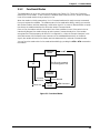
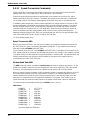
1.8 Controls on PC Board
The MultiModem is designed on a single printed circuit (PC) board. This board contains one 16-
position DIP-Switch (numbered 1-16). The DIP-Switches are accessible through a cut-out on the side
of the modem. There is also a knob which is used to adjust the speaker volume. This knob is
accessible through the modem's rear panel. The sixteen DIP-Switches control various modem
options or set default values for Command Mode operation. There is a difference in how several of
the switches operate depending on whether you are in synchronous or asynchronous mode. Refer to
the switch label on the bottom of the modem for an exact list of the switch functions in asynchronous
and synchronous operation. Chapter 9 of this manual also provides detailed instructions on
configuring all of the modem's PC board options.

18
MultiModemBL User Guide

Chapter 2 - Installation and Connection

20
MultiModemBL User Guide
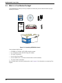
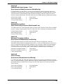
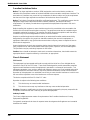
2.1 What is in Your Modem Package?
Your MultiModem is made up of many components. Make sure you have them all before trying to
operate your modem.
MADE IN U.S.A
MADE IN U.S.A
Figure 2-1. Unpacking (MT2834BL shown)
Your package should include:
• MT2834BL, MT1932BL or MT1432BL data/fax modem
• RJ-11 telephone cord or BS-6312 Plug (UK models)
• AC Power Transformer
• One (1) Quick Start Guide
• One (1) software CD (Trio
TM
data communications and fax software)
• This User Guide (on diskette)
If any of these items are missing, please refer to the Chapter 10 for information on contacting Tech
Support.
Page is loading ...
Page is loading ...
Page is loading ...
Page is loading ...
Page is loading ...
Page is loading ...
Page is loading ...
Page is loading ...
Page is loading ...
Page is loading ...
Page is loading ...
Page is loading ...
Page is loading ...
Page is loading ...
Page is loading ...
Page is loading ...
Page is loading ...
Page is loading ...
Page is loading ...
Page is loading ...
Page is loading ...
Page is loading ...
Page is loading ...
Page is loading ...
Page is loading ...
Page is loading ...
Page is loading ...
Page is loading ...
Page is loading ...
Page is loading ...
Page is loading ...
Page is loading ...
Page is loading ...
Page is loading ...
Page is loading ...
Page is loading ...
Page is loading ...
Page is loading ...
Page is loading ...
Page is loading ...
Page is loading ...
Page is loading ...
Page is loading ...
Page is loading ...
Page is loading ...
Page is loading ...
Page is loading ...
Page is loading ...
Page is loading ...
Page is loading ...
Page is loading ...
Page is loading ...
Page is loading ...
Page is loading ...
Page is loading ...
Page is loading ...
Page is loading ...
Page is loading ...
Page is loading ...
Page is loading ...
Page is loading ...
Page is loading ...
Page is loading ...
Page is loading ...
Page is loading ...
Page is loading ...
Page is loading ...
Page is loading ...
Page is loading ...
Page is loading ...
Page is loading ...
Page is loading ...
Page is loading ...
Page is loading ...
Page is loading ...
Page is loading ...
Page is loading ...
Page is loading ...
Page is loading ...
Page is loading ...
Page is loading ...
Page is loading ...
Page is loading ...
Page is loading ...
Page is loading ...
Page is loading ...
Page is loading ...
Page is loading ...
Page is loading ...
Page is loading ...
Page is loading ...
Page is loading ...
Page is loading ...
Page is loading ...
Page is loading ...
Page is loading ...
Page is loading ...
Page is loading ...
Page is loading ...
Page is loading ...
Page is loading ...
Page is loading ...
Page is loading ...
Page is loading ...
Page is loading ...
Page is loading ...
Page is loading ...
Page is loading ...
Page is loading ...
Page is loading ...
Page is loading ...
Page is loading ...
Page is loading ...
Page is loading ...
Page is loading ...
Page is loading ...
Page is loading ...
Page is loading ...
Page is loading ...
Page is loading ...
Page is loading ...
Page is loading ...
Page is loading ...
Page is loading ...
Page is loading ...
Page is loading ...
Page is loading ...
Page is loading ...
Page is loading ...
Page is loading ...
Page is loading ...
Page is loading ...
Page is loading ...
Page is loading ...
Page is loading ...
Page is loading ...
Page is loading ...
Page is loading ...
Page is loading ...
Page is loading ...
Page is loading ...
Page is loading ...
Page is loading ...
Page is loading ...
Page is loading ...
Page is loading ...
Page is loading ...
Page is loading ...
-
 1
1
-
 2
2
-
 3
3
-
 4
4
-
 5
5
-
 6
6
-
 7
7
-
 8
8
-
 9
9
-
 10
10
-
 11
11
-
 12
12
-
 13
13
-
 14
14
-
 15
15
-
 16
16
-
 17
17
-
 18
18
-
 19
19
-
 20
20
-
 21
21
-
 22
22
-
 23
23
-
 24
24
-
 25
25
-
 26
26
-
 27
27
-
 28
28
-
 29
29
-
 30
30
-
 31
31
-
 32
32
-
 33
33
-
 34
34
-
 35
35
-
 36
36
-
 37
37
-
 38
38
-
 39
39
-
 40
40
-
 41
41
-
 42
42
-
 43
43
-
 44
44
-
 45
45
-
 46
46
-
 47
47
-
 48
48
-
 49
49
-
 50
50
-
 51
51
-
 52
52
-
 53
53
-
 54
54
-
 55
55
-
 56
56
-
 57
57
-
 58
58
-
 59
59
-
 60
60
-
 61
61
-
 62
62
-
 63
63
-
 64
64
-
 65
65
-
 66
66
-
 67
67
-
 68
68
-
 69
69
-
 70
70
-
 71
71
-
 72
72
-
 73
73
-
 74
74
-
 75
75
-
 76
76
-
 77
77
-
 78
78
-
 79
79
-
 80
80
-
 81
81
-
 82
82
-
 83
83
-
 84
84
-
 85
85
-
 86
86
-
 87
87
-
 88
88
-
 89
89
-
 90
90
-
 91
91
-
 92
92
-
 93
93
-
 94
94
-
 95
95
-
 96
96
-
 97
97
-
 98
98
-
 99
99
-
 100
100
-
 101
101
-
 102
102
-
 103
103
-
 104
104
-
 105
105
-
 106
106
-
 107
107
-
 108
108
-
 109
109
-
 110
110
-
 111
111
-
 112
112
-
 113
113
-
 114
114
-
 115
115
-
 116
116
-
 117
117
-
 118
118
-
 119
119
-
 120
120
-
 121
121
-
 122
122
-
 123
123
-
 124
124
-
 125
125
-
 126
126
-
 127
127
-
 128
128
-
 129
129
-
 130
130
-
 131
131
-
 132
132
-
 133
133
-
 134
134
-
 135
135
-
 136
136
-
 137
137
-
 138
138
-
 139
139
-
 140
140
-
 141
141
-
 142
142
-
 143
143
-
 144
144
-
 145
145
-
 146
146
-
 147
147
-
 148
148
-
 149
149
-
 150
150
-
 151
151
-
 152
152
-
 153
153
-
 154
154
-
 155
155
-
 156
156
-
 157
157
-
 158
158
-
 159
159
-
 160
160
-
 161
161
-
 162
162
-
 163
163
-
 164
164
-
 165
165
-
 166
166
-
 167
167
-
 168
168


Multi-Tech Systems BL-Series User manual
- Category
- Networking
- Type
- User manual
Ask a question and I''ll find the answer in the document
Finding information in a document is now easier with AI
Related papers
-
Multitech BA-Series User manual
-
-
Multitech MT202TD 1200 User manual
-
-
Multi-Tech Systems BA-Series User manual
-
Multi-Tech Systems MTCBA-E-U User manual
-
-
-
-
Other documents
-
Black Box MD1640A User manual
-
Motorola ME-560M User manual
-
MaxTech PCI Internal Voice/FAX/Data/Speakerphone Modem User manual
-
-
-
Tandy 1400LT User manual
-
-
Acer FAX/Voice/Data Modem User manual
-
 Paradyne COMSPHERE 3800PLUS Reference guide
-
Telewell TW-5614UL User manual
