Ingersoll-Rand 115 User manual
- Category
- Power impact wrenches
- Type
- User manual

Refer All Communications to the Nearest
Ingersoll--Rand Office or Distributor.
Ingersoll--Rand Company 2001
PrintedinU.S.A.
03539525
Form P7080
Edition 5
September , 2001
INSTRUCTIONS FOR SERIES
115, 115--EU, 116, 116--EU, 117 AND 117--EU AIR HAMMERS
NOTE
Series 115, 115--EU, 116, 116--EU, 117 and 117--EU Air Hammers are designed for
exhaust system work, front end work and for general cutting , ch ip p ing and scraping.
Ingersoll--Rand is not responsible for customer modification of tools for applications
on which Ingersoll--Rand was not consulted.
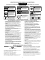
IMPORTANT SAFETY INFORMATION ENCLOSED.
READ THIS MANUAL BEFORE OPERATING TOOL.
IT IS THE RESPONSIBILITY OF THE EMPLOYER TO PLACE THE INFORMATION
IN THIS MANUAL INTO THE HANDS OF THE OPERATOR.
FAILURE TO OBSERVE THE FOLLOWING WARNINGS COULD RESULT IN INJURY.
PLACING TOOL IN SERVICE
• Always operate, inspect and maintain this tool in
accor dance with al l regulations (local, state,
federal and country), that may apply to hand
held/hand operated pneumatic tools.
• For safety, top performance, and maximum
durability of parts, operate this tool at 90 psig
(6.2 bar/620 kPa) maximum air pressure at the
inlet with 5/16” (8 mm) inside diameter air supply
hose.
• Always turn off the air supply and disconnect the
air supply hose before installing, removing or
adjusting any accessory on this tool, or before
performing any maintenance on this tool.
• Do not use damaged, frayed or deteriorated air
hoses and fittings.
• Be sure all hoses and fittings are the correct size
and are tightly secured. See Dwg. TPD905--1 for a
typical piping arrangement.
• Keep clear of whipping air hoses. Shut off the
compressed air before approaching a whipping air
hose.
• Always use clean, dry air at 90 psig maximum air
pressure. Dust, corrosive fumes and/or excessive
moisture can ruin the motor of an air tool.
• Do not lubricate tools with flammable or vol atile
liquids such as kerosene, diesel or jet fuel.
• Do not remove any labels. Replace any damaged
label.
USING THE TOOL
• Always wear eye protection when operating or
performing maintenance on this tool.
• Always wear hearing protection when operating
this tool.
• Keep hands, loose clothing, long hair and jewelry
away from rotating end of tool.
• Keep body stance balanced and firm. Do not
overreach when operating this tool. Anticipate and
be alert for sudden changes in motion, reaction
torques, or forces during start--up and operation.
• Tool shaft may continue to impact briefly after
throttle is released.
• Air powered tools can vibrate in use. Vibration,
repetitive motions or uncomfortable positions may
be harmful to your hands and arms. Stop using
any tool if discomfort, tingling feeling or pain
occurs. Seek medical advice before resuming use.
• Use accessories recommended by Ingersoll--Rand.
• This tool is not designed for working in explosive
atmospheres.
• This tool is not insulated against electric shock.
• Prevent exposure and breathing of harmful dust
and particles created by power tool use:
Some dust created by power sanding, sawing,
grinding, drilling and other construction
activities contains chemicals known to cause
cancer, birth defects or other reproductive
harm. Some examples of these chemicals are:
-- lead from lead based paints,
-- crystalline silica from bricks and cement
and other masonry products, and
-- arsenic and chromium from chemically
treated lumber.
Your risk from these exposures varies,
depending on how often you do this type of
work. To reduce your exposure to these
chemicals: work in a well ventilated area, and
work with approved safety equipment, such as
those dust masks that are specially designed to
filter out microscopic particles.
NOTE
The use of other than genuine Ingersoll--Rand replacement parts may result in safety hazards, decreased tool
performance , and increased maintenance, and may invalidate all warranties.
Repairs should be made only by authorized trained personnel. Consult your nearest Ingersoll--Rand Authorized
Servicenter.
GB

2
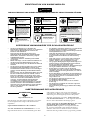
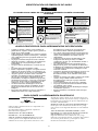
WARNING SYMBOL IDENTIFICATION
FAILURE TO OBSERVE THE FOLLOWING WARNINGS COULD RESULT IN INJURY.
Always wear eye protection
when operating or perform-
ing maintenance on this tool.
WARNING
WARNING
Always wear hearing
protection when operating
this tool.
Always turn off the air sup-
ply and disconnect the air
supply hose before install-
ing, removing or adjusting
any accessory on this tool,
or before performing any
maintenance on this tool.
WARNING
Air powered tools can vibrate
in use. Vibration, repetitive
motions or uncomfortable po-
sitions may be harmful to your
hands and arms. Stop using
any tool if discomfort, tingling
feeling or pain occurs. Seek
medical advice before resum-
ing use.
WARNING
Do not carry the tool by the
hose.
WARNING
WARNING
Do not use damaged, frayed
or deteriorated air hoses
and fittings.
WARNING
Keep body stance balanced
and firm. Do not overreach
when operating this tool.
WARNING
Operate at 90 psig (6.2 bar/
620 kPa) Maximum air pres-
sure.
90 psig
(6.2bar/620kPa)
International Warning Label:
Order Part No. ___________
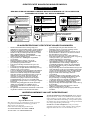
PERCUSSIVE TOOL SPECIFIC WARNINGS
• When wearing gloves and operating models with
inside trigger, always be sure that the glove s will
not prevent the trigger from bei ng released.
• Wear safety shoes, hard hat, safety goggles, gloves,
dustmask and any other appropriate protective
clothing while operating the tool.
• Do not indulge in horseplay. Distraction can cause
accidents.
• Keep hands and fingers away from the throttle
lever until it is time to operate the tool.
• Never rest the tool or chisel on your foot.
• Never point the tool at anyone.
• Compressed air is dangerous. Never point an air
hose at yourself or co--workers.
• Never blow cl othes free of dust with compressed
air.
• Be sure all hose connections are tight. A loose hose
not only leaks but can come completely off the tool
and while whipping under pressure, can injure the
operator and others in the area. Attach safety
cables to all hoses to prevent injury in case a hose
is accidentally broken.
• Never disconnect a pressurized air hose. Always
turn off the air supply and bleed the tool before
disconnecting a hose.
• The operator must keep limbs and body clear of
the chisel. If a chisel breaks, the tool with the
broken chisel projecting from the tool will
suddenly surge forward.
• Do not ride the tool with one leg over the handle.
Injury can result if the chisel breaks while riding
the tool.
• Know what is underneath the material being
worked. Be alert for hidden water, gas, sewer,
telephone or electric lines.
• Use only proper cleaning solvents to clean parts.
Use only cleaning solvents which meet current
safety and health standards. Use cleaning solvents
in a well ventilated area.
• Do not flush the tool or clean any parts with diesel
fuel. Diesel fuel residue will ignite in the tool when
the tool is operated, causing damage to internal
parts. When using models with outside triggers or
throttle levers, take c are when setting the tool
down to prevent accidental operation.
• Do not operate the tool with broken or damaged
parts.
• Never start the tool when it is lying on the ground.
• This tool is not designed for working in explosive
atmospheres.
• This tool is not insulated against electric shock.
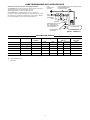
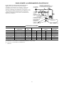
PLACING TOOL IN SERVICE
LUBRICATION
Ingersoll--Rand No. 10
Always use an air line lubricator with these tools.
We recommend the following Filter--Lubricator--Regulator
Unit:
For International -- No. C08-- C2--FKG0
F o r U S A -- N o . C 0 8 -- 0 2 -- F K G 0 -- 2 8
Before attaching the air hose, place several drops of
Ingersoll--Rand No. 10 Oil into the air inlet. This should
be done each day even when an air line lubricator is used.
During the working day, che ck the tool to ensure that the
retainer component s are lubricated.
After each two or three hours of operation, unless an air
line lubricator is used, place several drops of Ingersoll--
Rand No. 10 Oil into the air inlet.
Before storing Air Hammer or if the tool is to be idle
for a period exceeding 24 hours, pour about 3 cc of
Ingersoll--Rand No. 10 Oil into the air inlet and operate
the tool for 5 seconds. This will coat the internal parts
with oil and prevent rusting while the tool is idle.

3
PLACING TOOL IN SERVICE
Never use a heavy oil or an oil that forms gum.
Either will clog the small parts, restrict valve motion
and cause loss of efficiency. If the operation of the
Hamme r becomes sluggish, pour 3 cc of a clean, suitabl e
cle aning solution into the air inlet and operate the tool for
30 seconds. Lubricate in t he regular manner immediately
after flushing.
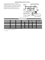
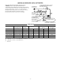
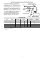
M
A
IN LINES 3 TIMES
AIR TOOL INL ET SIZE
TO
AIR
SYSTEM
TO
AIR
TOOL
LUBRICATOR
REGULATOR
FILTER
BRANCH LINE 2 TIMES
AIR TOOL INL ET SIZE
DRAIN REGULARLY
COMPRESSOR
(Dwg. TPD905--1)
SPECIFICATIONS
Model Type of
Handle
Impact/min. Stroke Length HSound Level
dB (A)
♦Vibrations
Level
in. mm Pressure •Power m/s
2
115, 115--EU pistol grip 5 000 1-- 5/8 41 -- -- -- -- -- -- -- -- --
116, 116--EU pistol grip 3 500 2-- 5/8 67 104.4 117.4 30.0
117, 117--EU pistol grip 2 000 3-- 1/2 89 103.5 116.5 46.4
116H, 116H--EU pistol grip 3 500 2-- 5/8 67 104.4 117.4 30.0
117H, 117H--EU pistol grip 2 000 3-- 1/2 89 103.5 116.5 46.4
H Tested in accordance with PNEUROP PN8NTC1.2 under load
♦ Tested in accordance with ISO8662--2
• ISO3744

Ingersoll-Rand, Co.
Swan Lane, Hindley Green, Wigan WN2 4EZ, U. K.
(1994 → ) XUA XXXXX →
EN292 ISO8662 PNEUROP PN8NTC1
Series 115-EU, 116-EU, and 117-EU Air Hammers
98/37/EC
September, 2001
September, 2001
4
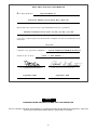
DECLARATION OF CONFORMITY
We
(supplier’s name)
(address)
declare under our sole responsibility that the product,
to which this declaration relates, is in compliance with the provisions of
Directives.
By using the following Principle Standards:
Serial No. Range
D. Vose Patrick Livingston
Name and signature of authorised persons Name and signature of authorised persons
Date Date
NOTE
SAVE THESE INSTRUCTIONS. DO NOT DESTROY.
When the life of the tool has expired, it is recommended that the tool be disassembled,
degreased and parts be separated by material so that they can be recycled.
Page is loading ...
Page is loading ...
Page is loading ...
Page is loading ...
Page is loading ...
Page is loading ...
Page is loading ...
Page is loading ...
Page is loading ...
Page is loading ...
Page is loading ...
Page is loading ...
Page is loading ...
Page is loading ...
Page is loading ...
Page is loading ...
Page is loading ...
Page is loading ...
Page is loading ...
Page is loading ...
Page is loading ...

26
PART NUMBER FOR ORDERING
REFERENCE POUR COMMANDE DE LA PIECE
BESTELLNUMMER
NUMERO DEL PEZZO PER L’ORDINAZIONE
SIMBOLO DE LA PIEZA PARA PEDIDOS
BESTELNUMMERS
1 Handle 17 Valve Cap Alignment Pin (small
for115 ................ 115--59 diameter)................... 115--32
for115--EU............. 115--EU--59 18 Barrel Assembly (includes piston)
for 116, 116H, 117 for115 ................ 115--A6
and117H .............. 117--59 for116 ................ 116--A6
for 116--EU, 116H--EU, for116H ............... 116H--A6
117--EU and 117H--EU . . . 117--EU--59 for117 ................ 117--A6
1A Warning Label for117H ............... 117H--A6
for 115, 116, 116H, 117 19 SpringRetainer.............. 115--183
and117H .............. WARNING- - 6 - - 99 20 Exhaust Deflector (for 117 and
for models ending in--EU . . EU--99 117Honly) ................. 117--23
2 Throttle Ball Seat ............ 116--303 21 Namepl ate
3 Throttle Plunger Assembly .... 117--A64 for115 ................ 115--301
4 Throttle Plunger O --ring (2) . . 117--168 for115--EU............. 115--EU--301
5 Throttle Ball ................ 116--50 for116 ................ 116--301
6 Throttle Ball Spring .......... 116--11 for116--EU............. 116--EU--301
7 InletBushing ............... 117--565 for116H ............... 116H --301
8 PowerRegulatorAssembly .... 117--A250 for117 ................ 117--301
9 RegulatorO--ring .......... 117--167 for117--EU............. 117--EU--301
10 RegulatorRetainingPin ....... 116--120 for117H ............... 117H--301
11 Trigger .................... 115--93 22 NameplateDriveScrew(2) .... 222--302
12 TriggerPin .................
..
116--121 23 BodyShopChiselKit......... 116--K5
13 ValveSeat..................
..
115--3
14 Valve...................... 115--2
15 ValveCap .................. 115--4
16 Valve Cap Alignment Pin (large
diameter)................... 115--31

27
Service Centers
Centres d’entretien
Ingersoll--Rand Niederlassungen
Centri d i Assistenza
Centros de Servicio
Service Centra
Ingersoll--Rand Company
510 Hester Drive
White House, TN 37188
USA
Tel: (615) 672 0321
Fax: (615) 672 0801
Ingersoll--Rand Sales Company Limited
Chorley New Road
Horwich, Bolton
Lancashire BL6 6JN
England -- UK
Tel: (44) 1204 880890
Fax: (44) 1204 880388
Ingersoll--Rand Equipements de Production
111 Avenue Roger Salongro
BP 59
F--59450 Sin Le Noble
France
Tel: (33) 27 93 0808
Fax: (33) 27 93 0800
Ingersoll--Rand GmbH
Gewerbeallee 17
45478 Mülhelm/Ruhr
Deutschland
Tel: (49) 208 99940
Fax: (49) 208 9994445
Ingersoll--Rand Italiana SpA
Casella Postale 1232
20100 Milano
Italia
Tel: (39) 2 950561
Fax: (39) 2 95380169
Ingersoll--Rand
Camino de Rejas 1, 2--18 B1S
28820 Coslada (Madrid)
España
Tel: (34) 1 669 5850
Fax: (34) 1 669 6054
Ingersoll--Rand Nederland
Produktieweg 10
2382 PB Zoeterwoude
Nederland
Tel: (31) 71 452200
Fax: (31) 71 218671
Ingersoll--Rand Company SA
PO Box 3720
Alrode 1451
South Africa
Tel: (27) 11 864 3930
Fax: (27) 11 864 3954
Ingersoll--Rand
Scandinavian Operations
Kastruplundgade 221
DK--2770 Kastrup
Danmark
Tel: (45) 32 526092
Fax: (45) 32 529092
Ingersoll--Rand SA
The Alpha Building
Route des Arsenaux 9
CH--1700 Fribourg
Schweiz/Suisse
Tel: (41) 37 205111
Fax: (41) 37 222932
Ingersoll--Rand Company
Kuznetsky Most 21/5
Entrance 3
103698 Moscow
Russia
CIS
Tel: (7) 501 882 0440
Fax: (7) 501 882 0441
Ingersoll--Rand Company
16 Pietro
Ul Stawki 2
PL--00193 Warsaw
Poland
Tel: (48) 2 635 7245
Fax: (48) 2 635 7332
-
 1
1
-
 2
2
-
 3
3
-
 4
4
-
 5
5
-
 6
6
-
 7
7
-
 8
8
-
 9
9
-
 10
10
-
 11
11
-
 12
12
-
 13
13
-
 14
14
-
 15
15
-
 16
16
-
 17
17
-
 18
18
-
 19
19
-
 20
20
-
 21
21
-
 22
22
-
 23
23
-
 24
24
-
 25
25
-
 26
26
-
 27
27


Ingersoll-Rand 115 User manual
- Category
- Power impact wrenches
- Type
- User manual
Ask a question and I''ll find the answer in the document
Finding information in a document is now easier with AI
in other languages
- italiano: Ingersoll-Rand 115 Manuale utente
- français: Ingersoll-Rand 115 Manuel utilisateur
- español: Ingersoll-Rand 115 Manual de usuario
- Deutsch: Ingersoll-Rand 115 Benutzerhandbuch
- Nederlands: Ingersoll-Rand 115 Handleiding
Related papers
-
Ingersoll-Rand 772 Operation and Maintenance Manual
-
-
-
-
-
-
-
-
-
Other documents
-
Ingersoll Rand 1111 Owner's manual
-
Facom V.331AH User manual
-
-
-
Matco Tools MT1724 Operating Instructions Manual
-
GYS MINI GRINDER BOX SET Ø 50 & 75mm Owner's manual
-
Sioux Tools SDR6P Original Instructions Manual
-
-
-
ATD Tools ATD-2150 User manual