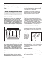
Weslo AIR STRIDER is an innovative elliptical trainer that blends advanced engineering with contemporary styling to provide you with a no-impact, total body workout in the convenience and privacy of your own home. This state-of-the-art fitness machine is designed to help you achieve your fitness goals quickly and effectively. With its smooth, fluid motion, the Weslo AIR STRIDER provides a low-impact workout that is easy on your joints. The adjustable resistance levels allow you to customize your workout to your own fitness level, making it suitable for both beginners and experienced exercisers.
Weslo AIR STRIDER is an innovative elliptical trainer that blends advanced engineering with contemporary styling to provide you with a no-impact, total body workout in the convenience and privacy of your own home. This state-of-the-art fitness machine is designed to help you achieve your fitness goals quickly and effectively. With its smooth, fluid motion, the Weslo AIR STRIDER provides a low-impact workout that is easy on your joints. The adjustable resistance levels allow you to customize your workout to your own fitness level, making it suitable for both beginners and experienced exercisers.


-
 1
1
-
 2
2
-
 3
3
-
 4
4
-
 5
5
-
 6
6
-
 7
7
-
 8
8
-
 9
9
-
 10
10
-
 11
11
-
 12
12
-
 13
13
-
 14
14
-
 15
15
-
 16
16


Weslo AIR STRIDER User manual
- Type
- User manual
- This manual is also suitable for
Weslo AIR STRIDER is an innovative elliptical trainer that blends advanced engineering with contemporary styling to provide you with a no-impact, total body workout in the convenience and privacy of your own home. This state-of-the-art fitness machine is designed to help you achieve your fitness goals quickly and effectively. With its smooth, fluid motion, the Weslo AIR STRIDER provides a low-impact workout that is easy on your joints. The adjustable resistance levels allow you to customize your workout to your own fitness level, making it suitable for both beginners and experienced exercisers.
Ask a question and I''ll find the answer in the document
Finding information in a document is now easier with AI
Related papers
Other documents
-
FreeMotion SFSR82308.0 User manual
-
-
-
-
NordicTrack FREESTRIDER 35 S User manual
-
FreeMotion SFSR84407.0 User manual
-
Pro-Form PFEL53408.0 User manual
-
Trojan Strider 200 Owner's manual
-
-