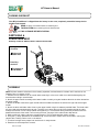
Billy Goat HP3400 is a versatile and easy-to-use mower that is perfect for a variety of lawn care tasks. With its powerful 344cc engine and 34-inch cutting deck, the HP3400 can mow even the thickest grass with ease. The mower also features a mulching kit and a grass catcher kit, so you can choose the option that best suits your needs. Whether you're looking to mulch your grass clippings to fertilize your lawn or bag them for easy disposal, the HP3400 has you covered.
Billy Goat HP3400 is a versatile and easy-to-use mower that is perfect for a variety of lawn care tasks. With its powerful 344cc engine and 34-inch cutting deck, the HP3400 can mow even the thickest grass with ease. The mower also features a mulching kit and a grass catcher kit, so you can choose the option that best suits your needs. Whether you're looking to mulch your grass clippings to fertilize your lawn or bag them for easy disposal, the HP3400 has you covered.


-
 1
1
-
 2
2
-
 3
3
-
 4
4
-
 5
5
-
 6
6
-
 7
7
-
 8
8
-
 9
9
-
 10
10
-
 11
11
-
 12
12
-
 13
13
-
 14
14
-
 15
15
-
 16
16
-
 17
17
-
 18
18
-
 19
19
-
 20
20
-
 21
21
-
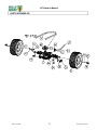 22
22
-
 23
23
-
 24
24


Billy Goat HP3400 is a versatile and easy-to-use mower that is perfect for a variety of lawn care tasks. With its powerful 344cc engine and 34-inch cutting deck, the HP3400 can mow even the thickest grass with ease. The mower also features a mulching kit and a grass catcher kit, so you can choose the option that best suits your needs. Whether you're looking to mulch your grass clippings to fertilize your lawn or bag them for easy disposal, the HP3400 has you covered.
Ask a question and I''ll find the answer in the document
Finding information in a document is now easier with AI
Related papers
-
Billy Goat SC181HEU User manual
-
Billy Goat FM3301EB User manual
-
-
Briggs & Stratton FM3300E User manual
-
-
-
-
-
-
Billy Goat 510223 User manual
Other documents
-
 MOWOX MNA192211 User manual
-
LumiSource LS-VIVIDFL XX User manual
-
 Love The Drive BMW 1 convertible wind deflector 128i, 135i Installation guide
-
 Love The Drive BMW 2 convertible wind deflector 218i, 225i, 228i, 230i, M235, M240 from 2014 to 2021 Installation guide
-
Simplicity FZ1301H User manual
-
 Love The Drive Mini convertible 2004 to 2015 wind deflector Installation guide
-
-
Poulan 966681801 User manual
-
 Gravely 911411 WAW 34 User manual
-
Toro Mid-Size ProLine Gear, 15 hp w/ 52" SD Mower User manual


