Dynaudio IP 24
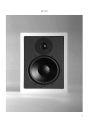
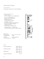
The Dynaudio IP 24 is a high-end in-wall loudspeaker system that utilizes high technology drivers designed specifically for the in-wall application. The sonic performance is more on par with a pair of freestanding high-end loudspeakers, and the sound will be recognized only as that of a true Dynaudio.
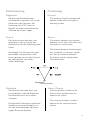
The IP 24 is designed to operate satisfactorily in a wide range of cavity volumes, ideally above 30 Litres. Avoid installing the speakers in the same cavity as any ducts, which may result in rattle. Placement near the intersection of a wall/ceiling, wall/floor or in a corner is not recommended, as it may result in too much coloration to the sound quality. If possible, keep the IP 24 more than 20” (0.5m) away from wall edges.
Dynaudio IP 24
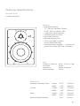
The Dynaudio IP 24 is a high-end in-wall loudspeaker system that utilizes high technology drivers designed specifically for the in-wall application. The sonic performance is more on par with a pair of freestanding high-end loudspeakers, and the sound will be recognized only as that of a true Dynaudio.
The IP 24 is designed to operate satisfactorily in a wide range of cavity volumes, ideally above 30 Litres. Avoid installing the speakers in the same cavity as any ducts, which may result in rattle. Placement near the intersection of a wall/ceiling, wall/floor or in a corner is not recommended, as it may result in too much coloration to the sound quality. If possible, keep the IP 24 more than 20” (0.5m) away from wall edges.


-
 1
1
-
 2
2
-
 3
3
-
 4
4
-
 5
5
-
 6
6
-
 7
7
-
 8
8
-
 9
9
-
 10
10
-
 11
11
-
 12
12
-
 13
13
-
 14
14
-
 15
15
-
 16
16
-
 17
17
-
 18
18
-
 19
19


Dynaudio IP 24
The Dynaudio IP 24 is a high-end in-wall loudspeaker system that utilizes high technology drivers designed specifically for the in-wall application. The sonic performance is more on par with a pair of freestanding high-end loudspeakers, and the sound will be recognized only as that of a true Dynaudio.
The IP 24 is designed to operate satisfactorily in a wide range of cavity volumes, ideally above 30 Litres. Avoid installing the speakers in the same cavity as any ducts, which may result in rattle. Placement near the intersection of a wall/ceiling, wall/floor or in a corner is not recommended, as it may result in too much coloration to the sound quality. If possible, keep the IP 24 more than 20” (0.5m) away from wall edges.
Ask a question and I''ll find the answer in the document
Finding information in a document is now easier with AI
in other languages
- Deutsch: Dynaudio IP 24 Benutzerhandbuch
Related papers
-
Dynaudio IP 17 Owners Manual Installation Product
-
-
-
-
-
-
-
-
-
Other documents
-
Canton InWall 845 Datasheet
-
Dali PHANTOM E-60 S Owner's manual
-
Audio Design Crunch Definition DSX4.2C Owner's manual
-
-
RCS BC-512EN Owner's manual
-
MB QUART QS165W Installation guide
-
-
Helix DARK BLUE User manual
-
-