Page is loading ...

Owners
Manual
FOR POTABLEWATER
HEATING ONLY
NOT SUITABLEFOR
SPACEHEATING
Model No.
153.317020 2 GaL
LISTED
Caution:
Read and Follow
All Safety Rules and
Operating Instructions
Before First Use of
This Product.
Savethis Manual for Future Reference.
POINT OF USE
ELECTRIC
WATER HEATER
• Safety Instructions
• Installation
• Operation
• Care and Maintenance
• Troubleshooting
• Parts List
GAMA certification appliesto all residential electric water heaters with
capacitiesof 20 to 120 Gallons. Inputrating of 12Kw or lessat a voltage
no greater than 250_L
_WARNING
READ THE GENERAL SAFETY SECTION BEGINNING ON INSIDE COVER
AND THEN THIS ENTIRE MANUAL BEFORE INSTALLING OR OPERAT-
ING THIS WATER HEATER.
Sears, Roebuck and Co., Hoffman Estates, IL 60179 U.S.A.
Printed inthe U.S.A. 1203 www.sears.com Part No. 184734-000

Safety Precautions
AWARNING J
Improper installation, adjustment, alteration, service or
maintenance can cause DEATH, SERIOUS BODILY
INJURY,OR PROPERTY DAMAGE. Refer to this manual J
for assistanceor consult your localSears Service Center
for further information.
AWARNING
At thetime ofmanufacturethis waterheaterwasprovidedwith
a combinationtemperature-pressuresrelief valvecertifiedbya
nationallyrecognizedtestinglaboratory that maintainsperiodic
inspectionof productionof listedequipmentor materials,as
meeting therequirementsfor ReliefValvesandAutomaticGas
ShutoffDevicesforHot Water SupplySystems,andthe current
editionof ANSI Z21.22, CSA4.4andthe coderequirementsof
ASME. If replaced, the valvemust meet the requirements of
localcodes,but not lessthana combinationtemperatureand
_ressurerelief valvecertifiedasmeeting the requirements for
ReliefValvesandAutomaticGasShutoffDevicesfor Hot Water
SupplySystems,ANSI Z21.220 CSA4.4 bya nationallyrecog-
nizedtestinglaboratorythat maintains periodicinspectionof
_roductionoflistedequipmentor materials.
The valvemustbemarkedwith a maximum setpressurenot
to exceedthe marked hydrostaticworkingpressureof the
water heater (150 Ibs./sq.in.) and a dischargecapacitynot
lessthan the water heater inputrate asshownonthe model
rating plate.(Electricheaters, watts dividedby 1000x 3412
equalBTU/Hr. rate.)
Yourlocaljurisdictionalauthority,whilemandatingthe useofa
temperature-pressurereliefvalvecomplyingwithANSI Z21.22,
CSA 4.4andASME,may require a valvemodeldifferentfrom
theonefurnishedwiththe waterheater
Compliancewithsuchlocalrequirements must besatisfiedby
the installeror end userof thewater heaterwith a locallypre-
scribedtemperature-pressurereliefvalveinstalledinthe desig-
nated openingin the water heater in placeof thefactory fur-
nishedvalve.
Forsafeoperationofthe waterheater,therelief valvemust not
beremovedfromit'sdesignatedopeningor plugged.
The temperature-pressurerelief valvemust beinstalleddirectly
intothef'_ingofthe waterheaterdesignatedforthe reliefvalve.
Positionthe valvedownwardandprovidetubingsothatanydis-
chargewill exit onlywithin6 inchesabove,or at anydistance
belowthe structural floor.Be certainthat no contactismade
withany liveelectricalpart The dischargeopeningmust not be
blockedor reducedin sizeunderanycircumstances.Excessive
length,over 30feet,or useofmore than fourelbowscancause
restrictionandreducethe dischargecapacityofthevalve.
No valveor otherobstructionisto beplacedbetweentherelief
valveandthetank. Do not connecttubingdirectlyto discharge
drainunlessa 6"airgapisprovided.Topreventbodilyinjury,haz-
ardto life,or propertydamage,the reliefvalvemust beallowed
to dischargewaterinquantitiesshouldcircumstancesdemand.If
the dischargepipeisnot connectedto a drainor othersuitable
means,thewaterflowmaycausepropertydamage.
The DischargePipe:
• Must not be smallerin sizethan the outlet pipesizeof
the valve, or have any reducing couplings or other
restrictions.
• Mustnot bepluggedor blocked.
• Mustbeofmaterial listed for hotwater distribution.
• Must be installedso as to allow complete drainageof
boththe temperature-pressurerelief valve,and the dis-
chargepipe.
• Mustterminate at an adequatedrain.
• Mustnothaveanyvalvebetweentbereliefvalveandtank.
AWARNING J
HAZARD OF ELECTRICAL SHOCK! Before removing
any access panels or servicing the water heater, make J
sure the electrical supply to the water heater isturned
"OFF". Failure to do this could result in DEATH, SERI-
OUS BOD LY NJURY,OR PROPERTY DAMAGE.
AWARNING
HOTTER WATER CAN SCALD: Water heaters are
intended to produce hot water. Water heated to a tem-
)erature which will satisfy space heating, clothes washing,
dish washing, and other sanitizing needs can scald and
_ermanently injure you upon contact. Some people are
more likely to be permanently injured by hot water than
others. These include the elderly, children, the infirm, or
physically/mentally handicapped. If anyone using hot
water in your home fits into one of these groups or if
there is a local code or state law requiring a certain tem-
)erature water at the hot water tap, then you must take
special precautions. In addition to using the lowest possi-
ble temperature setting that satisfies your hot water
needs, a means such as a mixing valve, shall be used at
the hot water taps used by these people or at the water
heater. Mixing valves are available at plumbing supply or
hardware stores. Follow manufacturers instructions for
installation of the valves. Before changing the factory set-
ting on the thermostat, read the "Temperature
Regulation" section in this manual.
AWARNING
WATER HEATERS EQUIPPED FOR ONE VOLTAGE
ONLY: This water heater isequipped for one type voltage
only. Check the rating plate near the bottom access panel
for the correct voltage. DO NOT use this water heater
with any voltage other than the one shown on the model
rating plate. Failure to use the correct voltage can cause
problems which can result in DEATH, SERIOUS BODILY
INJURY, OR PROPERTY DAMAGE. If you have any ques-
tions or doubts consult your electric company.
AWARNING
INSULATING JACKETS: When installing an external
water heater insulation jacket on an electric water
heater:
a. DO NOT cover the temperature-pressure relief valve.
b. DO NOT put insulation over the access covers or any
access areas.
c. DO NOT remove operating instructions, and safety
related warning labels and materials affixed to
the water heater.
d. DO obtain new warning and instruction labels from
Sears for placement on the jacket directly over the
existing labels.
AWARNING
Do not usethis applianceif anypart of it hasbeen under
water. An electrical short or malfunction couldoccur.The
water heater shouldbe replaced.
2
A CAUTION
WATER HEATERS EVENTUALLY LEAK: Installation of
the water heater must be accomplished in such a manner
that if the tank or any connections should leak, the flow of
water will not cause damage to the structure. When such
locations cannot be avoided, a suitable drain pan should
be installed under the water heater. Drain pans are avail-
able at your local Sears Store. Such a drain pan must be
piped to an adequate drain.

Table of Contents
Safety Precautions ............................................................................................................................................2
Table of Contents .............................................................................................................................................3
Customer Responsibilities ...................................................................................................................4
Product Specifications ...............................................................................................................................4
Materials and Basic Tools Needed ..........................................................................................5
Materials Needed ...................................................................................................................................................................... 5
Basic _Ibols................................................................................................................................................................................ 5
Installation Instructions
Removing the Old Water Heater. ............................................................................................................................................ .6
Facts to Consider About the Location ..................................................................................................................................... .7
Optional Wall Mounting ..................................................................................................................................................... .7, 8
Water Piping ............................................................................................................................................................................ .8
_l_mpemture-Pressure Relief Valve............................................................................................................................................ .9
Filling the Water Heater .......................................................................................................................................................... 10
Optional Cord Set .................................................................................................................................................................. 10
Wiring Diagrams .................................................................................................................................................................. 10
Wiring .................................................................................................................................................................................... 11
Installation Checklist .............................................................................................................................................................. 12
Service and Adjustment
*l_mpemture Regulation .......................................................................................................................................................... 13
Thermostats ............................................................................................................................................................................ 13
*l_mpemture Settings .............................................................................................................................................................. 13
Thermostat Adjustment .......................................................................................................................................................... 13
*l_mpePature-Pressure Relief Valve Operation .......................................................................................................................... 14
Draining ................................................................................................................................................................................. 14
Element Cleaning/Replacement ........................................................................................................................................ 15-17
Drain Valve Washer Replacement ........................................................................................................................................... 17
Service .................................................................................................................................................................................... 17
Troubleshooting Guide
Start Up Conditions ............................................................................................................................................................... 18
Tbennal Expansion ............................................................................................................................................................... 18
Strange Sounds ..................................................................................................................................................................... 18
Operational Conditions .................................................................................................................................................... 19, 20
Smelly Water ......................................................................................................................................................................... 19
"Air" in Hot Water Faucets .................................................................................................................................................. 19
Rumbling Noise .................................................................................................................................................................... 19
High "Ihnperature Shut Of}'System ............................................................................................................................... 19, 20
Not Enough or No Hot _T&ter............................................................................................................................................. 20
Water Is _IboHot ................................................................................................................................................................. 20
Leakage Checkpoints ............................................................................................................................................................. 21
Parts Order List ........................................................................................................................................... 22, 23
Warranty .....................................................................................................................................................................24

Customer Responsibilities
Thank You for purchasing a Sears water heater.
Properly installed and maintained, it should give you years of
trouble free service. If you should decide that you want the new
water heater professionally installed by Sears call the local
Service Center or any Sears store. They will arrange for prompt,
quality installation by Sears authorized contractors.
The installation must conform with the instructions in this
manual; electric company rules; and Local Codes, or in the
absence of Local Codes, with the current edition of the NEC,
National Electrical Code NFPA 70. This publication is available
from your local government or public library or electric compa-
ny or by writing Underwriters Laboratories Inc., 333 Pfingsten
Road, Northbrook, 1L60062.
Abbreviations Found In This Instruction Manual
U.L. - Underwriters Laboratories Inc., 333 Pfingsten Rd.,
Northbrook, IL 60062
NEC - National Electrical Code
ANSI - American National Standards Institute
• Read the "Safety Precautions" section, page 2 of this manual
first and then the entire manual carefully, lfyou don't follow
the safety rules, the water heater will not operate properly. It
could cause DEKFH, SERIOUS BODILY INJURY AND/OR
PROPERTY DAMAGE.
This manual contains instructions for the installation, opera-
tion, and maintenance of this electric water heater. It also con-
tains warnings throughout the manual that you must read and
be aware ot: All warnings and all instructions are essential to
the proper operation of the water heater and your safety. Since
we cannot put everything on the first few pages, READ THIS
ENTIRE MANUAL BEFORE ATTEMPTING TO
INSTALL OR OPERATE THE WXFER HEATER.
• If after reading this manual you have any questions or do not
understand any portion of the instructions, call Sears
Service Center.
Carefully plan the place where you are going to put the water
heater. Correct electrical wiring and connections are very
important in preventing death from possible electrical shock
and fires. Examine the location to ensure the water heater com-
plies with the "Facts to Consider About the Location" section.
For California installation this water heater must be braced,
anchored, or strapped to avoid falling or moving during an
earthquake. See instructions for correct installation procedures.
Instructions may be obtained from your local dealer, whole-
saler, public utilities or California Office of the State Architect,
400 P Street, Sacramento, CA 95814.
Massachusetts Code requires this water heater to be installed
in accordance with Massachusetts 248-CMR 2.00: State
Plumbing Code and 248-CMR 5.00.
Product Specifications
MODEL
NUMBER
153.317020
TANK
CAPACITY
IN GALLONS
2
DIMENSIONS IN INCHES
DIAMETER HEIGHT
10" 12¾"
RECOVERY RATE
GALS. PER HOUR
@ 90°E RISE
7
ELEMENT
WATTAGE
120 Volt
1440
MINIMUM
WIRE SIZE*
(GAUGE)
12
MAXIMUM FUSE
OR CIRCUIT
BREAKER
SIZE (AMPS)
20
*Wiring size based on standard 60°C copper wire. If distance from fuse box to water heater is more than 90 feet, refer to your local elec-
trical code.
4

Materials and Basic Tools Needed
Materials Needed
"Ib simplify the installation Sears has available the installation
parts shown below. You may or may not need all of these materi-
als, depending on your type of installation.
WATER HEATER INSTALLA.
TION KIT WITH FLEXIBLE
CONNECTORS FOR 3/4" OR
1/2" THREADED OR COPPER
PLUMBING
EXPANSION TANKS FOR THERMAL
EXPANSION CONDITIONS AVAILABLE
IN 2 GALLON CAPACITY THROUGH
LOCAL SEARS SERVICE CENTERS
DRAIN PANS AVAILABLE IN 20"
DIAMETER FOR WATER HEATERS
HAVING A DIAMETER 18" OR LESS,
24" DIAMETER FOR WATER
HEATERS HAVING A DIAMETER 22"
OR LESS AND AVAILABLE IN 28"
DIAMETER FOR WATER HEATERS
HAVING A DIAMETER 26" OR LESS
Basic Tools
You may or may not need all of these tools, depending on your
type of installation. These tools can be purchased at your local
Sears store.
Pipe Wrench (2) 14"
Screwdriver
6 Foot Tape or Folding Rule
Garden Hose
Drill
Pipe Dope or Teflon Tape
6 FOOT TAPE
GARDEN HOSE
SLOT-HEAD SCREWDRIVER
PIPE
WRENCH
PHILLIPS SCREWDRIVER
PIPE DOPE (SQUEEZE TUBE) _//
roll of teflon tape DRILL
(Use only on water connections)
ADDITIONAL TOOLS NEEDED WHEN
SWEAT SOLDERING
Tubing Cutters or Hacksaw
Propane Torch
Soft Solder
Solder Flux
Emery Cloth
Wire Brushes
HACKSAW
3/4" WIRE BRUSH
1/2" WIRE BRUSH
PROPANE TORCH
ROLL OF LEAD FREE
SOFT SOLDER
ROLL OF EMERY SOLDER TUBING
CLOTH FLUX CUTTER

Installation Instructions
Removing the Old Water
Heater
Q'Ihrn "OFF" electrical supply to the water heater.
('_ "lh ...... pplyrn OFF the water su to the water heater at
the water shutoffvalve orwater meter.
Attach a hose to the water heater drain
valve and put the other end in a floor
drain or outdoors. Open the water heater
drain valve. Open a nearby hot water
faucet which will relieve pressure in the
water heater and speed draining.
Qa. If you have piping to the water heater,
copper
the two copper water pipes can be cut with a
hacksaw approximately 4" away from where
they connect to the water heater. This will
avoid cutting off the pipes too short.
Additional cuts can be made later if necessary.
Disconnect the temperature-pressure relief
valve drain line. When the water heater is
drained, disconnect the hose from the drain
valve. Close the drain valve. The water heater
is now completely disconnected and ready to
be removed.
®
Q b. If you have galvanized pipe to the
water heater, loosen the two gal-
vanized pipes with a pipe wrench
at the union in each line. Also
disconnect the piping remaining
to the water heater. These pieces
should be saved since they may be
needed when reconnecting the
new water heater. Disconnect the
temperature-pressure relief valve
drain line. When the water heater
is drained, disconnect the hose
from the drain valve. Close the
drain valve. The water heater is
now completely disconnected and
ready to be removed.
_,WARNING ]
The water passingout ofthe drain valvemay beextreme- ]
ly hot. To avoidbeing scalded,make sure all connectionsI
are tight and that the water flow is directed away from
any person.
Q Gheck make the electrical isagainto
supply
sure
turned OFF to the water heater. Then unplug the
water heater (cord set) or disconnect the electrical sup-
ply connection from the water heater junction box.
_ CLAMP _ ___ ACCESS OPENING
HEATER
WIRING
CAUTION I
Mineral buildupor sediment may haveaccumulatedin the
old water heater. This causes the water heater to be I
much heavier than normal and this residue, if spilledout,
could causestaining.
6

Installation Instructions (cont'd)
Facts to Consider About the
Location
You should carefully choose an indoor location for the new
water heater, because the placement is a very important consid-
eration for the safety of the occupants in the building and for
the most economical use of the appliance. This water heater is
not intended for outdoor installation.
Whether replacing an old water heater or putting the water
heater in a new location, the following critical points must he
observed.
WALLSTUD
PLYWOOD(MIN.½" MIN. 2"x 4"WHICH LAPSAT
THICKNESS)LAPINGAT LEASTTWO WALLSTUDS
LEASTTWO WALLSTUDS
8_¼" x 3"
WOOD SCREWS
/x
• The location selected should be indoors as close to and as
centralized with the water piping system as possible. This
water heater, as well as all water heaters, will eventually leak.
Do not install without adequate drainage provisions where
water flow will cause damage.
_i,CAUTION
WATER HEATERS EVENTUALLY LEAK: Installation of
the water heater must be accomplished in such a manner
that if the tank or any connections should leak, the flow of
water will not cause damage to the structure. When such
locations cannot be avoided, a suitable drain pan should
be installed under the water heater. Drain pans are avail-
able at your local Sears stores. Such a drain pan must be
piped to an adequate drain.
WATER HEATER
MOUNTING BRACKETS
_, CAUTION
INSTALLATION IN RESIDENTIAL GARAGES: The I
water heater must be located and/or protected so it is
not subject to phys ca damage by a mov ng veh c e.
• The location selection must provide adequate clearances for
servicing and proper operation of the water heater.
Optional Wall Mounting
_,WARNING J
Wall constructionat the point of the water heater instal-
at on must becapabe ofsupport ng at east 200 pounds.
As an example: if the water heater is to be installed on a wall of
gypsum board (dry wall) or other material not capable of sup-
porting the water heater filled with water, additional bracing will
be necessary. "I_vopossibilities are shown below.
[Figure,] IFigu.e21
1. Using two sheet metal screws supplied, secure the top mount-
ing bracket to the top of the water heater.
SECURING SCREWS
_ (SUPPLIED!
UPPER !.... • ,_ #8-18x_/_ i! oIIW !¢ 11
BRACKET _L I -J 1
C 3
2. Using the remaining two sheet metal screws provided, secure
the bottom mounting bracket to the bottom of the water
heater.
LOWER
BRACKET
SECURING
SCREWS
(SUPPLIED)
#8-18 x %'_
7

Installation Instructions (cont'd)
Optional Wall Mounting (cont'd)
3. Determine the location on the wall, and then the height
above the floor which the wall securing bracket will be
placed. Using adequate screws, or nuts and bolts (not sup-
plied), fasten the wall securing bracket to the wall.
SECURING SCREW TO
WALL M[N. 12 x _Z,_'
"_"-- "_I (NOT SUPPLIED)
"-I
_ SECURING SCREWTO
WALL MIN. 12x%"
(NOT SUPPLIED)
Water Piping
*A WARNING
HOTTER WATER CAN SCALD: Water heaters are intend-
ed to produce hot water. Water heated to a temperature
vhich will satisfy space heating, clothes washing, dish wash-
ing, and other sanitizing needs can scald and permanently
injure you upon contact. Some people are more likely to be
_ermanently injured by hot water than others. These
include the elderly, children, the infirm, or physically/men.
tally handicapped. If anyone using hot water in your home
fits into one of these groups or if there is a local code or
state law requiring a certain temperature water at the hot
water tap, then you must take special precautions. In addi-
tion to using the lowest possible temperature setting that
satisfies your hot water needs, a means such as a mixing
valve, shall be used at the hot water taps used by these peo-
ple or at the water heater. Mixing valves are available at
plumbing supply or hardware stores. Follow manufacturers
instructions for installation of the valves. Before changing
the factory setting on the thermostat, read the
"Temperature Regulation" section in this manual.
HOT WATER A
OUTLET T
TEMPERED_
WATER OUTL
*MIXING VALVE WATER OUTLET
ON WATER HEATER
COLD WATER
_¢TO COLD WATER
INLET ON
WATER HEATER
If a water heater is installed in a closed water supply system;
such as one having a back-flow preventer, check valve, water
meter with a check valve, etc.., in the cold water supply; means
must be provided to control thermal expansion. Contact the
local utility or SearsServiceCenter on how to control this situation.
The illustration shows the attachment of the water piping to thewater
heater. The water heater isequipped with _" water connections.
• Look at the top of the water heater. The hot water outlet is
marked hot. Put two or three turns of teflon tape around the
threaded end of the compression coupling and around the _"
threads of the 5_"x ½"reducer bushing. Put two or three turns of
teflon..... tape around both ends,of a Vd'threaded_,, nip le (not.sup-
plied in the mstallauon kit). Attach the Z threa_ed topple to
the _" x }_"reducer bushing and screw into the hot water outlet
of the water heater. Using flexible connectors, connect the hot
water pipe to the hot water outlet ofthe water heater.
NOTE: If using copper tubing, solder tubing to an
adapter before attaching the adapter to the water connec-
tions. Do not solder the water supply lines directly to the
connections of the water heater. It will harm the fittings
on the water heater.
Look at the top of the water heater. The cold water inlet is
marked cold. Put two or three turns of teflon tape around the
threaded end of the compression coupling and around the _"
threads of the 5_"x ½"reducer bushing. Put two or three turns of
teflon..... tape around both ends,of a Vd'threaded_,, nip_jple(not.sup-
plied m the mstallauon kzt). Attach the Z threaded topple to
the _" x Vd'reducer bushing and screw into the cold water inlet
of the water heater. Using flexible connectors, connect the hot
water pipe to the hot water outlet oftile water heater.
NOTE: Your water heater is insulated to minimize heat
loss from the tank. Further reduction in heat loss can be
accomplished by insulating the hot water lines from the
water heater.
Installation COMPLETED using
Installation Kit
SHUT-OFF
1/2" x314" REDUCER_ _ 1/2" x3/4" REDUCER
BUSHING BUSHING
1/2 THREADED_ _,_ _1/2 THREADED
NIPPLE (not supplied _ ..--_Y_ ...... _ NIPPLE (not supplied
with installation kit) /_--_-_-J_-_ _ "\with installation kit)
-----¢.1

Installation Instructions (cont'd)
Temperature-Pressure
Relief Valve
&WARNING
At the time of manufacture this water heater was provided
with a combination temperature-pressures relief valve certi-
fied by a nationally recognized testing laboratory that main-
tains periodic inspection of production of listed equipment
or materials, as meeting the requirements for Relief Valves
and Automatic Gas Shutoff Devices for Hot Water Supply
Systems, and the current edition of ANSI Z21.22 • CSA 4.4
and the code requirements of ASME. If replaced, the valve
must meet the requirements of local codes, but not less
than a combination temperature and pressure relief valve
certified as meeting the requirements for Relief Valves and
Automatic Gas Shutoff Devices for Hot Water Supply
Systems, ANSI Z21.22, CSA 4.4 by a nationally recognized
testing laboratory that maintains periodic inspection of pro-
duction of listed equipment or materials.
The valve must be marked with a maximum set pressure
not to exceed the marked hydrostatic working pressure of
the water heater (150 Ibs./sq. in.) and a discharge capacity
not less than the water heater input rate as shown on the
model rating plate. (Electric heaters, watts divided by 1000
x 3412 equal BTU/Hr. rate.)
Your local jurisdictional authority, while mandating the use
of a temperature-pressure relief valve complying with ANSI
Z21.22 0 CSA 4.4 and ASME, may require a valve model dif-
ferent from the one furnished with the water heater.
Compliance with such local requirements must be satisfied
by the installer or end user of the water heater with a locally
)rescribed temperature-pressure relief valve installed in the
designated opening in the water heater in place of the facto-
ry furnished valve.
For safe operation of the water heater, the relief valve must
not be removed from it's designated opening or plugged.
The temperature-pressure relief valve must be installed
directly into the fitting of the water heater designated for
the relief valve. Position the valve downward and provide
tubing so that any discharge will exit only within 6 inches
above, or at any distance below the structural floor. Be cer-
tain that no contact is made with any live electrical part.
The discharge opening must not be blocked or reduced in
size under any circumstances. Excessive length, over 30 feet,
or use of more than four elbows can cause restriction and
reduce the discharge capacity ofthe valve.
No valve or other obstruction is to be placed between the
relief valve and the tank. Do not connect tubing directly to
discharge drain unless a 6" air gap is provided. To prevent
bodily injury, hazard to life, or property damage, the relief
valve must be allowed to discharge water in quantities
should circumstances demand. If the discharge pipe is not
connected to a drain or other suitable means, the water flow
may cause property damage.
The Discharge Pipe:
Must not be smaller in size than the outlet pipe size of
the valve, or have any reducing couplings or other
restriction.
Must not be plugged or blocked.
Must be of material listed for hot water distribution.
Must be installed so as to allow complete drainage of
both the temperature-pressure relief valve, and the dis-
charge pipe.
Must terminate at an adequate drain.
Must not have any valve between the relief valve and tank.
&WARNING
The temperature-pressure relief valve must be manually
operated at least once a year. Caution should be taken to
ensure that (I) no one is in front of or around the outlet
of the temperature-pressure relief valve discharge line,
and (2) the water manually discharged will not cause any
bodily injury or property damage because the water may
be extremely hot.
If after manually operating the valve, it fails to completely
reset and continues to release water, immediately, close
the cold water inlet to the water heater, follow the drain-
ing instructions, and replace the temperature-pressure
relief valve with a new one.
._(
HOT
VALVE
COLD
LIRE-PRESSURE
RELIEF VALVE
DISCHARGE PIPE
(Do not cap or
plug. Provide a 6"
air gap between
pipe and drain.)
.FLOOR
DRAIN
WARNING "RELIEF VALVE OPENING"
11dewatel beateris prowbedw_ha ¢0mb[natbnT_l_lp6emtule_PressureRelbf Valvelisiodas coEy_01y[nlgw_/
thesbe'dafdfor ReliefValves a'tl A_lomatbGasShddl Oevicestor HotWaterS®#y System& AN$ Z2122
aid tie coderedei_le_Ls ofASME
Your10caJiu_odictmn_Jauthe(_y,whilenland_ng tie useofa Temp_ature-PmssureReliefValvecomplying
_ith AN8Z2122 and ASME,mayrequirea valvemodeld_ferentflora theone_rnisbedwiththewatelheater
Com_ian_ withSUChIoca_requile_'_r_smusthe satisfiedbythe ins[aHerelenduser oftie watel beaterwith
a locally prescribed TemberaIure,PiessureRelief VaJveinstaJlodin t_ desighated ®ening in thewater
heater
9
• Ifa shoIt shank (less lhan 2") temperature*pressure relief ValVeis to be inslalled
(as shown), a nipple and co®ling must be Used
• Ifa long shank (2" or brger) is to be installed, de not use the nipple and co®ling
'Insta_lTer®eralure_Pressule protec_veeq_pment redeirodby IocaJcodes, bL4notlessthai a combina*
lien Temperatule.Presst_reRelief V_lve certified as meeting Ibe redeilements for Relief Valves and
AulomaticGas$betdf Deviceslor Hot-WalerSubelySystems,ANSZ2122 by _ nadena_lyrecognizedtest_
_g laboratorytbe_msJntainsperiodb in_on Ofproductionof listed edeipment or matelbJs The valve
must be ortentod,j3iowbedw_thtub_rg,el otbervaseinstsJlodso_at d_scharge•caqex_•only _thin_6 inches
above,orat anydlstaqcebelowthestfuctt_ra_f_oor,aod c_{_ot cont_ any I_veelectnca_part¸
Fol safe®elation of_ waterbealel, _e R_l_efVahtemust notbe removedel _YULqge_J
See manual heading * 'Ternbetature*PressuleRelod V_]ve'r for ins®laden and maintenanceof Relief
Valve, dmcbergepipeard othersafely preeautJ®s

Installation Instructions (cont'd)
Filling the Water Heater Wiring Diagrams
"Ib fill the water heater with water:
• Close the water heater drain valve by turning the handle to
the right (clockwise). The drain valve is located on the lower
front of the water heater.
• Open the cold water supply valve to the water heater.
NOTE: The cold water supply valve must be left open
when the water heater is in use.
• _lb insure complete filling of the tank, allow air to exit by
opening the nearest hot water faucet. Allow water to run
until a constant flow is obtained. This will let air out of the
water heater and the piping.
A CAUTION J
Never use this water heater unlessit iscompletely full J
of water. To prevent damage to the tank and heating
element, the tank must be filled with water. Water I
must flow from the hot water faucet before turning
ON ' power.
• Check all new water piping for leaks. Repair as needed.
Optional Cord Set Wiring
(120Volt)
120 VOLT CORD SET
GREEN
There may be a cord set supplied with the water heater at the
time of manufacture. If not one can be ordered through the
Parts Department, see "Repair Parts" section. Refer to figureson
this page for wiring diagrams.
120 VOLT WIRING
THERMOSTAT
Lu GREEN
.JlGROONO
=
10

Installation Instructions (cont'd)
Wiring
CAUTION J
Never use this water heater unlessit iscompletely full J
of water. To prevent damage to the tank and heating
element, the tank must be filled with water. Water I
must flow from the hot water faucet before turning
ON ' power.
B. Rigid metal conduit, intermediate metal conduit, or elec-
trical metallic tubing may be used for the grounding
means if conduit ortubing is terminated in fittings
approved for grounding.
C. Flexible metal conduit or flexible metallic tubing shall be
permitted for grounding if all the following conditions
are met:
You must provide all wiring of the proper size outside of the
water heater. You must obey local codes and electric company
requirements when you install this wiring.
If you are not familiar with electric codes and practices, or if you
have any doubt, even the slightest doubt, in your ability to con-
nect the wiring to this water heater, obtain the service of a com-
petent electrician. Contact your Sears salesperson to arrange for
a professional electrician.
1.
2.
3.
The length in any ground return path does not exceed
6 feet.
The circuit conductors contained therein are protect-
ed by overcurrent devices rated at 20 amperes or less.
The conduit or tubing is terminated in fittings
approved for grounding. For complete grounding
details and all allowable exceptions, refer to the cur-
rent edition of the National Electrical Code, NFPA
70.
_,WARNING
WATER HEATERS EQUIPPED FOR ONE VOLTAGE
ONLY: This water heater isequipped for one type volt-
age only. Check the rating plate near the bottom
access panel for the correct voltage. DO NOT use this
water heater with any voltage other than the one
shown on the model rating plate. Failure to use the
correct voltage can cause problems which can result in
DEATH, SERIOUS BODILY INJURY, OR PROPERTY
DAMAGE. If you have any questions or doubts consult
your electric company.
4.
5.
6.
7.
A standard _" conduit opening has been made in the
water heater junction box for the conduit connection.
Use wire nuts and connect the power supply wiring to
the wires inside the water heater's junction box.
The water heater must be electrically "grounded" by
the installer. A green ground screw has been provided
on the water heater's junction box. Connect ground
wire to this location.
Replace the wiring junction cover using the screw
provided.
CAUTION
If wiring from your fuse box or circuit breaker box
was aluminum for your old water heater, replace
it with copper wire. If you wish to reuse the exist-
ing aluminum wire, have the connection at the
water heater made by a competent electrician.
Contact your Sears salesperson to arrange for a
professional electrician.
1. Provide a way to easily shut off the electric power when
working on the water heater. This could be with a circuit
breaker or fuse block in the entrance box or a separate dis-
connect switch.
TO SERVICE
PANEL
GREEN GROUND SCREW
GROUND
WIRE
WIRE NUT
CONNECTIONS
ACCESS Ot_Eb,!ING
HEATER
WIRING
2. Install and connect a circuit directly from the main fuse or
circuit breaker box. This circuit must be the right size and
have its own fuse or circuit breaker. Refer to the chart in the
"Product Specifications" section for the correct size wire and
fuse or circuit breaker.
3. If metal conduit is used for the grounding conductor:
A. The grounding electrode conductor shall be of copper,
aluminum, or copperclad aluminum. The material shall
be of one continuous length without a splice or joint.
11

Installation Instructions (cont'd)
Installation Checklist
ls the fuse or circuit breaker size correct as shown in the
chart in the "Product Specifications" section?
Are the wires from the circuit breaker or fuse service to the
water heaters' juncnon"" box on,,the correct wire size m,.,(_uge_
as shown in the chart in the Product Specifications sec-
tion?
TEMPERATURE-PRESSURE
RELIEF VALVE
SHUT-OFF
ls the new temperature-pressure relief valve properly
installed, and piped to an adequate drain? See "'l_mperature-
Pressure Relief Valve" section.
ls the water heater completely filled with water? See "Filling
the Water Heater" instructions in the "Installation
Instructions section.
• Will a water leak damage anything? See "Facts to Consider
About the Location" section.
• Are the cold and hot water lines connected to the water
heater correctly? See "Water Piping" instructions in the
"Installation Instructions" section.
Is there adequate clearance for maintenance around the
water heater?
Do you need to call your electric company to check your
wiring?
HOT WATER COLD WATER
DISCHARGE PIPE
(Do not cap or plug.
Provide a 6" air gap
between the end of the
pipe and drain.)
DRAIN VALVE
FLOOR DRAIN
MODEL RATING PLATE
12

Service and Adjustment
Temperature Regulation Temperature Settings
&WARNING
HOTTER WATER CAN SCALD: Water heaters are
intended to produce hot water. Water heated to a
temperature which will satisfy clothes washing, dish
washing, and other sanitizing needs can scald and per-
manently injure you upon contact. Some people are
more likely to be permanently injured by hot water
than others. These include the elderly, children, the
infirm, or physically/mentally handicapped. If anyone
using hot water in your home fits into one of these
groups or if there is a local code or state law requiring
a certain temperature water at the hot water tap,
then you must take special precautions. In addition to
using the lowest possible temperature setting that sat-
isfies your hot water needs, some type of tempering
device, such as a mixing valve, should be used at the
hot water taps used by these people or at the water
heater. Mixing valves are available at plumbing supply
or hardware stores. Follow manufacturers instructions
for installation of the valves, Before changing the
factory setting of the thermostat, read the
"Temperature Regulation" section in this manual.
_WARNING J
Never allow small children to use a hot water tap, J
or to draw their own bath water. Never leave a J
child or handicapped person unattended in a bath-
tub or shower.
Thermostats
The thermostat is factory set at a position which approximates
120°F (Hot) and is adjustable if a different water temperature is
desired. Read all warnings in this manual and on the water
heater before proceeding.
LO- Setting, approximately 95°F, is recommended for vaca-
tions or extended periods of no hot water.
HI- ls a setting for the maximum hot water usage approxi-
mately 140°F,which can be supplied by the water heater.
The temperature dial should be kept at a lower setting
whenever possible.
NOTE: Water temperature range of 120°--140°F recom-
mended by most dishwasher manufacturers.
t60°F About 1/2 seconds
150°F About I -1/2 seconds
140°F Lessthan Sseconds
130°F About 30 seconds
120°F Hore than 5 minutes
Thermostat Adjustment
The thermostat is adjustable if a different water temperature is
desired. Read all warnings in the "'f_mperature Regulation" sec-
tion before proceeding.
_,WARNING J
This specialthermostat with ECO (Part No. 9002394) can
only be usedwith this water heater.Do not use anyother I
thermostat with ECO. I
The thermostat of this water heater has been factory set at the
mid position which approximates 120°F (Hot) to reduce the risk
of scald injury. The thermostat is adjustable if a different water
temperature is desired. Read all warnings in this manual and on
the water heater before proceeding.
I ÷_® 3
_ 4
7© ©l
©
4
APPROXIMATE
TEMPERATURES
"lb adjust the temperature setting:
1. "_(hrn"OFF" the electrical power to the water heater at the
junction box.
AWARNING
HAZARD OF ELECTRICAL SHOCK! Before
removing any access panels or servicing the water
heater, make sure the electrical supply to the water
heater is turned "OFF". Failure to do this could
result in DEATH, SERIOUS BODILY INJURY, OR
PROPERTY DAMAGE.
2. _ihke off the access panel and fold away the insulation.
3. Turn the water temperature dial clockwise (f"--"N) to
increase the temperature, or counter clockwise (4"-"h) to
decrease the temperature.
4. Fold the insulation back in place and replace the accesspanel.
5. "ihrn "ON" the power supply.
AD USTABLE THERMOSTAT
13

Service and Adjustment (cont'd)
Temperature-Pressure Relief
Valve Operation
The temperature-pressure relief valve must be man-
ually operated at least once a year.
TEM PERATURE-PRESSU RE
ELIEF VALVE
11 DISCHARGE
!1 P,PE
Draining
The water heater should be drained if being shut down during
freezing temperatures. Also periodic draining and cleaning of
sediment from the tank may be necessary.
• Before beginning turn "OFF" the electric power supply to the
water heater.
AWARNING J
HAZARD OF ELECTRICAL SHOCK! Before removing
any access panels or servicing the water heater, make J
sure the electrical supplyto the water heater is turned
"OFF". Failure to do this could result in DEATH, SERI-
OUS BOD LY NJURY,OR PROPERTY DAMAGE.
• CLOSE the cold water inlet valve to the water heater.
AWARNING
The temperature-pressure relief valve must be manually
operated at leastonce a year.Caution shouldbe taken to
ensurethat (I) no one isin front of or aroundthe outlet
of the temperature-pressure relief valve discharge line,
and (2) the water manually dischargedwill not causeany
property damage or bodily injury. The water may be
extremely hot.
If after manually operatingthe valve,it failsto completely
reset and continuesto release water, immediately close
the coldwater inlet to the water heater,follow the drain-
ing instructions, and replace the temperature-pressure
relief valvewith a new one.
• OPEN a nearby hot water faucet and leave open to allow for
draining.
• Connect a hose to the drain valveand terminate to an adequate
drain or outdoors.
• OPEN the water heater drain valve to allow for tank draining.
NOTE: If the water heater is going to be shut down and
drained for an extended period, the drain valve should be
left open with hose connected allowing water to terminate
to an adequate drain.
• Close the drain valve.
Failure to install and maintain a new properly listed temperature-
pressure relief valve will release the manufacturer from any claim
which might result from excessivetemperature or pressure.
• Follow "Filling the Water Heater" instructions in the
"Installation Instructions" section.
• "Ihrn "ON" power to the water heater.
AWARNING
If the temperature-pressure relief valveon the appliance
weepsor dischargesperiodically,this may be due to ther-
mal expansion. Your water heater may have a check
valve installedin the water line or a water meter with a
checkvalve. Consult your local SearsService Center for
further information. Do not plug the temperature-pres-
surerelief valve.
A CAUTION J
Never use this water heater unlessit iscompletely full J
of water. To prevent damage to the tank and heating
element, the tank must be filled with water. Water I
must flow from the hot water faucet before turning
ON ' power.
14

Service and Adjustment (cont'd)
Element Cleaning/
Replacement
"Ib remove the element from your tank in order to clean or
replace it:
1. Before beginning turn "OFF" the electric power supply to the
water heater.
I
AWARNING
HAZARD OF ELECTRICAL SHOCK! Before
removing any access panels or servicing the water
heater, make sure the electrical supply to the water
heater is turned "OFF". Failure to do this could
result in DEATH, SERIOUS BODILY INJURY, OR
PROPERTY DAMAGE.
2. Turn off"the water supply to the water heater at the water
shutoff'valve or water meter.
3. Attach a hose to the water heater drain valve and put the
other end in a floor drain or outdoors. Open the water heater
drain valve. Open a nearby hot water faucet which will relieve
pressure in the water heater and speed draining.
_,WARNING J
The water passing out of the drain valve may be
extremely hot. To avoid being scalded, make sure all J
connections are tight and that the water flow is J
directed away from any person. J
4. Remove the two screws securing the access panel, and remove
panel.
5. Open the flap of insulation to expose the opening.
6. Lift out the tab a_sshown to unclip the terminal cover from
the thermostat. The terminal cover can now be removed
from the thermostat.
15

Service and Adjustment (cont'd)
Element Cleaning/
Replacement (cont'd)
7. Disconnect the two wires on the element and unscrew the
old element from the tank.
12. Open the cold water supply valve to the water heater.
NOTE: The cold water supply valve must be left open
when the water heater is in use.
13. "Ib insure complete filling of the tank, allow air to exit by
opening the nearest hot water faucet. Allow water to run
until a constant flow is obtained. This will let air out of the
water heater and the piping.
8. Clean the area around the element opening. Remove any
sediment from or around the element opening, inside the
tank.
9. If you are cleaning the element you have removed, do so by
scraping or soaking in vinegar or a de-liming solution.
AWARNING I
Replacement elements must (I) be the same volt-I
age and (2) no greater wattage than listed on the
mode rat ng p ate affixed to the water heater.
10. A new gasket should be used in all cases to prevent a possible
water leak. (See Element Gasket in the "Parts Order List"
Chart). Place the new element gasket on the thread side of
the cleaned or new element and screw into tank, securing
tightly using an element wrench.
A CAUTION J
Never use this water heater unless it is completely J
full of water. To prevent damage to the tank and J
heating element, the tank must be filled with water. J
Water must flow from the hot water faucet before
turn ng ' ON ' power.
14. Check element for water leaks. If leakage occurs, tighten
element or repeat steps 2 and 3, remove element and reposi-
tion gasket. Then repeat steps 10 through 14.
15. Reconnect the two wires to the element and then check to
make sure the thermostat remains firmly against the surface
of the tank.
£
11. Close the water heater drain valve by turning the handle to
the right (clockwise). The drain valve is on the lower front
of the water heater.
16. Replace terminal cover on thermostat and fold insulation
back over the element.
16

Service and Adjustment (cont'd)
Drain Valve Washer
Replacement
17. Fold the insulation back in place so that it completely covers
the thermostat and element.
NOTE: For replacement, use a _d' x _3Ad'x W' thick washer
available at your nearest hardware store. For ordering a
replacement washer, refer to the "Parts Order List" section.
18. Replace accesspanel.
19. "lhrn "ON" electric power to water heater.
• Before beginning turn "OFF" the electrical power supply to
the water heater.
AWARNING
HAZARD OF ELECTRICAL SHOCK! Before
removing any access panels or servicing the water
heater, make sure the electrical supply to the water
heater is turned "OFF". Failure to do this could
result in DEATH, SERIOUS BODILY INJURY, OR
PROPERTY DAMAGE.
• Follow "Draining" instructions in the "Service and
Adjustment" section.
• "Ihrning counter clockwise, remove the hex cap below the
screw handle.
• Remove the washer and put the new one in place.
%
A CAUTION J
Never use this water heater unless it is completely J
full of water. To prevent damage to the tank and J
heating element, the tank must be filled with water. J
Water must flow from the hot water faucet before
turn ng ' ON ' power.
• Screw the handle and cap assembly back into the drain valve
and retighten using a wrench. DO NOT OVER TIGHTEN.
• Follow "Filling the Water Heater" instructions in the
"Installation Instructions" section.
• Check for leaks.
• "Ihrn "ON" electric power to the water heater.
_ HANDLE AND
CAP ASSEMBLY
WASHER
Service
Before calling for repair service, read the "Start Up Conditions"
and "Operational Conditions" found in the Troubleshooting
Guide of this manual.
If a condition persists or you are uncertain about the operation
of the water heater, let a qualified person check it out.
Contact SEARS Repair Services at 1-800-4-MY-HOME
(1-800-469-4663)
17

Troubleshooting Guide
Start Up Conditions
THERMAL EXPANSION
Water supply systems may, because of such events as high line
pressure, frequent cut-off_, the effects of water hammer among
others, have installed devices such as pressure reducing valves,
check valves, back flow preventers, etc._to control these types of
_roblems. When these devices are not equipped with an internal
y-pass, and no other measures are taken, the devices cause the
water system to be dosed. As water is heated, it expands (ther-
mal expansion) and dosed systems do not allow for the expan-
sion of heated water.
The water within the water heater tank expands as it is heated and
increases the pressure of the water system. If the relieving point of
the water heater's temperature-pressure relief valve is reached, the
valve will relieve the excess pressure. The temperature-pressure
relief valve is not intended for the constant relief of thermal
expansion. This is an unacceptable condition and must be cor-
rected.
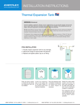
It is recommended that any devices installed which could create a
closed system have a by-pass and/or the system have an expan-
sion tank to relieve the pressure built by thermal expansion.
Thermal expansion tanks are available from Sears stores and
through the Sears Service Centers. Contact the local plumbing
inspector, water supplier and/or the Sears Service Center for
assistance in controlling these situations.
Thermal Expansion Tank Specifications
Model "I_tnkCapacity Dimensions in Inches ]Pipe Fitting
Number In Gallons Diameter [ Length [ On "lhnk
153.331020 2 8 inches ]12_ inches] _" Male
Expansion Tank Sizing Chart
Expansion Inlet*
_Ihnk Water
Capacity Pressure
Needed 40-80psi
Water Heater Capacity (Gallons)
2 4 6 10 19.9
2 2 2 2 2
HOT COLD
WATER HEATER
COLD WATER
INLET FITTING
MOT COLD
WATER HEATER (3)
COLD WATER PRESSURE
,INLET FITTING REDUCING
VALVEWITH
BY-PASS
O)
EXPANSION
TANK
(z)
PRESSUREGAUGE
WATER
SHUTOFF
RECOMMENDED INSTALLATION
(VERTICAL MOUNTING)
FLOOR,CEILING
JOIST,ETC.
STRAPPING
(0
EXPANSION
TANK
0)
PRESSURE
REDUCING INLET COLD
VALVEWITH WATER
BY-PASS SHUTOFF
(2)
PRESSUREGAUGE
ALTERNATE RECOMMENDED
INSTALLATION
(HORIZONTAL MOUNTING)
*Highest recorded inlet water pressure in a 24 hour period or
regulated water pressure.
NOTE= Expansion tanks are pre-charged with a 40 psi air
charge. If the inlet water pressure is higher than 40 psi, the
expansion tank's air pressure must be adjusted to match that
pressure, but must not be higher than 80 psi.
STRANGE SOUNDS
Possible noises due to expansion and contraction of"some metal
_arts during periods of heat-up and cool-down do not represent
armful or dangerous conditions.
18

Troubleshooting Guide
Operational Conditions
SMELLY WATER
In each water heater there is installed an anode rod for corrosion
protection of the tank. Certain water conditions will cause a
reaction between this rod and the water. The most common
complaint associated with the anode rod is one of a "rotten egg
smell". This odor is derived from hydrogen sulfide gas dissolved
in the water. The smell is the result of four factors which must
all he present for the odor to develop:
a. a concentration of sulfate in the supply water.
b. little or no dissolved oxygen in the water.
c. a sulfate reducing bacteria within the water heater. (This
harmless bacteria is non-toxic to humans.)
d. an excess of active hydrogen in the tank. This is caused by
the corrosion protective action of the anode.
The anode rod in a new glasslined water heater works rapidly to
protect the tank. After a period of time the anode action slows
and the odor may dissipate.
A smelly water condition (Rotten Egg Odor) in your Point of
Use water heater can, in most cases, be resolved or reduced with
the addition of sufficient amounts of chlorine to eliminate the
bacterial growth inside the tank. This can be accomplished
through the installation of a chlorine feeder to the system or the
periodic flushing of the water heater with "Chlorox" as needed.
On systems where the odor is mild and does not occur too
rapidly, a monthly flushing may be suf[]cient. In more severe
cases, a system feeder wouldbe more appropriate.
RUMBLING NOISE
In some water areas, scale or mineral deposits will build up on
your heating elements. This buildup will cause a rumbling noise.
Follow "Element Cleaning/Replacement" instructions to clean
and replace the elements.
HIGH TEMPERATURE SHUT OFF SYSTEM
The water heater has a high limit shut off system with a reset
button located on the thermostat.
Follow the resetting instructions which refer to the high limit
behind the access panel.
• Before beginning, turn "OFF" electrical power supply to the
water heater.
"AIR" IN HOT WATER FAUCETS
_,WARNING
HYDROGEN GAS: Hydrogen gas can be produced in a
hot water system that has not been used for a long period
of time (generally two weeks or more). Hydrogen gas is
extremely flammable and explosive. To prevent the possi-
bility of injury under these conditions, we recommend the
hot water faucet be opened for several minutes at the
kitchen sink before any electrical appliances which are
connected to the hot water system are used (such as a
dishwasher or washing machine). If hydrogen gas is pre-
sent, there will probably be an unusual sound similar to
air escaping through the pipe as the hot water faucet is
opened. There must be no smoking or open flame near
the faucet at the time it is open.
_,WARNING I
HAZARD OF ELECTRICAL SHOCK! Before removing
any access panels or servicing the water heater, make I
sure the electrical supply to the water heater isturned
"OFF". Failure to do this could result in DEATH, SERI-
OUS BOD LY NJURY,OR PROPERTY DAMAGE.
19

Troubleshooting Guide (cont'd)
HIGH TEMPERATURE SHUT OFF SYSTEM
(cont'd)
• Remove the two screws securing the access panel and remove
panel.
• Open the flap of insulation to expose the opening.
• Reset the high limit by pushing in the red button marked
"RESET".
0 I
@
run,_orr
p_x,_R
8t _IWO N_
RESET BUTTON
• Fold the insulation back in place so that it completely covers
the thermostat and element.
• Replace the access panel.
• *lhrn "ON" electric power to the water heater.
_, CAUTION J
If the high limit must be reset again, call Sears Service J
Department to find out whythe highlimit turned "OFF"
the e ectr c power.
NOT ENOUGH OR NO HOT WATER
In a new installation, the water heater may not be properly
connected. Make sure the cold water supply valve is open.
Review and check piping installation. Make sure that the
cold water line is connected to the cold water inlet to the
water heater and the hot water line to the hot water outlet
on the water heater.
Make sure the electrical supply to your water heater is
"ON".
Check for loose or blown fuses in your water heater circuit.
Circuit breakers weaken with age and may not handle their
rated load and should be replaced.
Make certain the disconnect switch, if used, is in the "ON"
position.
Check to see the electric service to your house has not been
interrupted. If this is the case, contact the electric company.
ls the thermostat set to the desired temperature? See
"*l_mperature Regulation" section.
If you had experienced very hot water and now no hot
water, the problem may be due to the high temperature
shut off"system. See "H!gh "_mperature Shut Off System"
in the "[i-oubleshooting section.
During very cold weather, the incoming water will also be
colder and it will require a longer time to become heated.
The hot water usage may exceed the capacity of the water
heater. If so, wait for water heater to recover after abnormal
demand. Also examine pipes and faucets for possible water
leaks.
If you can not determine the problem, then call the Sears
Service Department.
WATER IS TOO HOT
Adjust the thermostat to a lower setting. See the "_[hnperature
Regulation" section.
20
/