Page is loading ...

© Baxi Heating U.K. Limited 2008.
5112107/04
Model 347
RADIANT / CONVECTOR GAS FIRE
Fitted with one of the following fascia.
Brava 4 Oxysafe,
Charm 4 Oxysafe
or
Esquire 4 Oxysafe
(GC No. 32-032-62)
INSTALLER: Please leave this guide with the owner
INSTALLATION AND OWNER GUIDE
We trust that this guide gives
sufficient details to enable this
appliance to be installed and
maintained satisfactorily. However, if
further information is required, our
Valor Fires Technical Helpline will
be pleased to help.
Telephone 0844 8711 565 (National
call rates apply in the United
Kingdom).
In the Republic of Ireland
Telephone 0044 844 8711 565.

Baxi Heating U.K. Limited 2008.
All rights reserved. No part of this publication may be reproduced in any material form
(including photocopying), stored in any medium by electronic means (including in any
retrieval system or database) or transmitted, in any form or by any means, whether
electronic, mechanical, recording or otherwise, without the prior written permission of
the copyright owner.
Applications for the copyright owner's permission to reproduce any part of this
publication should be made, giving details of the proposed use, to the following
address: The Company Secretary, Baxi Heating UK Limited, The Wyvern Business
Park, Stanier Way, Derby, DE21 6BF.
Warning: Any person who does any unauthorised act in relation to a copyright work
may be liable to criminal prosecution and civil claims for damages.
Valor Fires, Erdington, Birmingham B24 9QP
www.firesandstoves.co.uk
Because our policy is one of constant development and improvement, details may vary slightly from
those given in this publication
Page 2
© Baxi Heating U.K. Limited 2008.
THIS APPLIANCE IS FOR USE WITH NATURAL GAS (G20).
WHEN CONVERTED USING CONVERSION KIT NUMBER 05347F1 THIS
APPLIANCE IS FOR USE WITH PROPANE GAS (G31).
THIS APPLIANCE IS SUITABLE ONLY FOR INSTALLATION IN THE UNITED
KINGDOM (GB) AND THE REPUBLIC OF IRELAND (IE).

Safety First.
Valor Fires fires are CE Approved and designed to meet the appropriate British
Standards and Safety Marks.
Quality and Excellence.
All Valor Fires fires are manufactured to the highest standards of quality and
excellence and are manufactured under a BS EN ISO 9001 quality system accepted
by the British Standards Institute.
The Highest Standards
Valor Fires is a member of SBGI and HHIC (Heating and Hot water Industry Council)
that work to ensure high standards of safety, quality and performance.
Careful Installation
Valor Fires is a CORGI registered company. All our gas fires must be installed by a
competent CORGI Registered Installer in accordance with our Installer Guide and
should not be fitted directly on to a carpet or floor of combustible material.
Page 3
© Baxi Heating U.K. Limited 2008.

Page 4
© Baxi Heating U.K. Limited 2008.
INSTALLER GUIDE
INSTALLER GUIDE
FOR OWNER GUIDE SEE PAGES 29 TO 43

CONTENTS
Section Heading Page
INSTALLER GUIDE 4 - 28
OWNER GUIDE 29 - 43
1 SAFETY 6
2 LIST OF ACCESSORIES 6
3 APPLIANCE DATA 7
4 GENERAL INSTALLATION REQUIREMENTS 8
5 PRE-INSTALLATION PREPARATION 15
5.1 Unpacking. 15
5.2 Fireplace flue pull. 15
5.3 Appliance preparation. 16
5.4 Fitting the battery to electronic ignition models. 16
5.5 Checking the ignition. 16
5.5.1 Manual ignition. 16
5.5.2 Electronic ignition. 17
5.6 Fitting the closure plate. 17
6 APPLIANCE INSTALLATION 19
6.1 Using the extension brackets. 19
6.2 Installing to a hearth. 19
6.3 Wall mounting. 20
6.4 Gas supply connection. 20
6.5 Radiants installation. 20
6.6 Flue restrictor adjustment. 21
7 CONTROL & PRESSURE CHECKS 22
7.1 Check control settings. 22
7.2 Flame supervision and spillage monitoring system. 22
7.3 Check reference pressure. 23
8 FASCIA FITTING 23
8.1 To fit the fascia. 23
8.2 To fit the closure plate baffle. 23
9 SPILLAGE CHECK 24
10 FINAL REVIEW 25
11 SERVICING & PARTS REPLACEMENT 26
11.1 To remove the fascia. 26
11.2 To replace radiant(s). 26
11.3 To replace the pilot unit. 26
11.4 To remove the piezo generator (manual ignition models). 27
11.5 Note for electronic ignition. 27
11.6 To remove the complete burner module, pipes and pilot. 27
11.7 To grease the gas tap 28
Page 5
© Baxi Heating U.K. Limited 2008.
INSTALLER GUIDE

1. SAFETY
Installer
Before continuing any further with the installation of this appliance please read
the following guide to manual handling.
The lifting weight (kg) of this appliance is as below:
Model
Heat Engine Fascia
Brava 10.15 7.39
Charm 10.15 7.39
Esquire 10.15 5.64
One person should be sufficient to lift the fire. If for any reason this weight is
considered too heavy then obtain assistance.
When lifting always keep your back straight. Bend your legs and not your back.
Avoid twisting at the waist. It is better to reposition your feet.
Avoid upper body/top heavy bending. Do not lean forward or sideways whilst
handling the fire.
Always grip with the palm of the hand. Do not use the tips of fingers for support.
Always keep the fire as close to the body as possible. This will minimise the
cantilever action.
Use gloves to provide additional grip.
Always use assistance if required.
2. LIST OF ACCESSORIES
Description Part number
Spigot extension 0595191
Page 6
© Baxi Heating U.K. Limited 2008.
INSTALLER GUIDE

3. APPLIANCE DATA
*When converted using kit 05347F1.
The appliance information label is on the inner face of the back panel at the lower left
hand side. It is visible when the fascia is removed.
This appliance does not contain any component manufactured from asbestos or
asbestos related products.
The efficiency of this appliance has been measured as specified in BS 7977 - 1 and
the result is as below :
Model
Efficiency % (Gross)
347 Brava, Charm & Esquire 71
The gross calorific value of the fuel has been used for this efficiency calculation. The
test data from which it has been calculated has been certified by Advantica
Certification services (0087). The efficiency value may be used in the UK
Government's Standard Assessment Procedure (SAP) for energy rating of dwellings.
Page 7
© Baxi Heating U.K. Limited 2008.
INSTALLER GUIDE
Gas Natural (G20) Propane (G31) *
Inlet Pressure 20mbar 37mbar
Input - Max. (Gross) 5.6kW (19,100 Btu/h) 5.3kW (18,084 Btu/h)
Input - Min. (Gross) 1.57W (5,357 Btu/h) 2.35kW (8,018 Btu/h)
Burner Test Pressure (Cold)
17.95 + 0.75mbar
(7.2 + 0.3in w.g.)
36.4 ± 0.75 mbar
(14.85 ± 0.3in w.g.)
Gas Connection 8mm pipe 8mm pipe
Burner Injector - Upper
(Centre Radiants)
Cat 28 - 185 Size 80
Burner Injector - Lower
(Outer Radiants)
Cat 28 - 185 Size 80
Pilot & Atmosphere Sensing
Device
OPNG9093 OPLPG9222
Ignition
Integral twin spark piezo
(Mounted on gas valve)
Integral twin spark piezo
(Mounted on gas valve)
Aeration Non-adjustable Non-adjustable

The conversion of net efficiency to gross was achieved by multiplying the net
efficiency by the following conversion factor from Table E3 of SAP 2005, rounding
down to the nearest whole number.
4. GENERAL INSTALLATION REQUIREMENTS
4.1 The installation must be in accordance with these instructions.
For the user’s protection, in the United Kingdom it is the law that all gas appliances
are installed by competent persons in accordance with the current edition of the Gas
Safety (Installation and Use) Regulations. Failure to install the appliance correctly
could lead to prosecution. CORGI requires its members to work to recognised
standards.
In the United Kingdom the installation must also be in accordance with:
All the relevant parts of local regulations.
All relevant codes of practice.
The relevant parts of the current editions of the following British Standards:-
BS 715
BS EN 1806 which replaces BS 1289 Part 2
BS 5440 Part 1
BS 5440 Part 2
BS 6891
BS 1251
BS EN 1856 Part 1 which replaces BS 4543 Part 2
BS 5871 Part 1
BS EN 1858 which replaces BS 1289 Part 1
BS 6461 Part 1
In England and Wales, the current edition of the Building Regulations issued by
the Department of the Environment and the Welsh Office.
In Scotland, the current edition of the Building Standards (Scotland) Regulations
issued by the Scottish Executive.
In Northern Ireland, the current edition of the Building regulations (Northern
Ireland) issued by the Department of the Environment for Northern Ireland.
In the republic of Ireland the installation must be carried out by a competent
person and installed in accordance with:
a) The current edition of IS 813 “Domestic gas installations”.
b) All relevant national and local rules in force.
c) The current building regulations
Where no specific instructions are given, reference should be made to the relevant
British Standard Code of Practice.
Page 8
© Baxi Heating U.K. Limited 2008.
Gas Conversion factor from net to gross efficiency
Natural Gas 0.901
LPG 0.921
INSTALLER GUIDE

4.2 If the appliance is intended to be installed to a chimney that was previously
used for solid fuel, the flue must be swept clean prior to installation. All flues should
be inspected for soundness and freedom from blockages.
4.3 Any chimney dampers or restrictors should be removed. If removal is not
possible they must be fixed in the open position.
4.4 Normal adventitious ventilation is usually sufficient to satisfy the ventilation
requirements of this appliance. In GB reference should be made to BS 5871 Part 2
and in IE reference should be made to the current edition of IS 813 “Domestic gas
Installations” which makes clear the conditions that must be met to demonstrate that
sufficient ventilation is available.
4.5 Note that soft wall coverings (e.g. embossed vinyl, etc.) are easily affected by
heat. They may scorch or become discoloured when close to a heating appliance.
Please bear this in mind when installing.
4.6 The minimum allowable distance from the outside of the appliance fascia to a
corner wall having combustible material or any other combustible surface which
projects beyond the front of the appliance is 50mm at either side (See figure 1).
Although no side clearance is necessary to non-combustible surfaces we recommend
a 100mm clearance for service access to fascia side fixing.
Page 9
© Baxi Heating U.K. Limited 2008.
INSTALLER GUIDE
Figure 1. Dimensions and clearances
Model Dimension ‘A’ (mm) Dimension ‘B’ (mm) Dimension ‘C’ (mm)
Brava 609 713 177
Charm 609 713 177
Esquire 609 708 177

4.7 The appliance must not be installed in any room, which contains a bath, or
shower or where steam is regularly present.
4.8 An extractor fan may only be used in the same room as this appliance, or in any
area from which ventilation for the appliance is taken, if it does not affect the safe
performance of the appliance. Note the spillage test requirements detailed further on
in this manual. If the fan is likely to affect the appliance, the appliance must not be
installed unless the fan is permanently disconnected.
4.9 The appliance is fitted with an A.S.D (Atmosphere sensing device). If the
appliance closes down after a period of operation for no apparent reason, the
consumer should be informed to stop using the appliance until the installation and
appliance have been thoroughly checked. The A.S.D will shut the appliance down if
an unacceptable amount of harmful products of combustion accumulate. Under no
circumstances should the A.S.D be altered or bypassed in any way. Only genuine
manufacturers replacement parts should be fitted.
4.10 Allow a minimum clearance of 90mm from the top surface of the appliance
fascia to the underside of any shelf whether it is made from combustible or non-
combustible materials. This clearance is necessary to allow the fascia to be lifted off
for servicing and also allows the owner sufficient access to operate the control knob.
For a shelf made from wood or other combustible materials deeper than 150mm,
add 12.5mm to the clearance for every 25mm of additional shelf depth (See graph 1).
Page 10
© Baxi Heating U.K. Limited 2008.
Graph 1. Shelf clearances
INSTALLER GUIDE

4.11 In the United Kingdom, as supplied, this appliance can be installed in the
following situations: -
4.11.1 The appliance must be mounted on a non-combustible hearth except when
the conditions in section 4.11.4 are met (N.B. conglomerate marble hearths are
considered as non-combustible). The hearth must be at least 680mm wide x 300mm
deep. The hearth material must be at least 12mm thick. The periphery of the hearth
(or fender) should be at least 50mm above floor level to discourage the placing of
carpets or rugs over it.
The appliance can be fitted to a purpose made proprietary class “O” 150°C surround.
Note: A spigot extension is available (Baxi part number 0595191). When fitted this
shall extend through the closure plate for at least 15mm and have a minimum
clearance of 50mm from the end to any surface.
4.11.2 Conventional fireplace
The fireplace opening must be within the following dimensions:
(*)
The total height of the closure plate is 660mm and will accommodate a maximum
opening height of 650mm (This allows a 10mm overhang). Heights above
580mm (Inclusive of sealing tape) will leave the sealing tape and closure plate visible
above the appliance. A baffle is supplied with the fire which can be screwed to the
appliance to cover the sealing tape and closure plate. When using the baffle, the
height of the sealing tape and closure plate can be extended to a maximum 630mm
before being visible (See section 8.2).
4.11.3 Precast flues
The appliance can be installed to a fireplace that has a properly constructed precast
concrete or clay flue block system conforming to BS EN 1806 or BS1289. The
appliance is suitable for installations conforming to older versions of BS1289 as well
as the current standards. The flue blocks must have a minimum width not less than
63mm and a cross-sectional area not less than 13,000mm
2
. Older editions of BS1289
required a cross-sectional area of 13,000mm
2
. The current revision of the standard
requires 16,500mm
2
. This appliance is suitable in both cases.
The chimney should be one or two storeys high but not less than 3m vertical height
and be correctly terminated. No mortar fangs between the blocks should be extruded
into the flueway. If raking blocks are used, they must be fitted in accordance with the
manufacturer’s instructions. Mortar must not be allowed to drop down and accumulate
in the raked positions.
The fireplace opening must be within the following dimensions:
Page 11
© Baxi Heating U.K. Limited 2008.
Width Height
Max. 440mm
Min. 305mm
Max. 610mm
(*)
Min. 544mm
INSTALLER GUIDE

(a)
The total height of the closure plate is 660mm and will accommodate a maximum
opening height of 650mm (This allows a 10mm overhang). Heights above
580mm (Inclusive of sealing tape) will leave the sealing tape and closure plate visible
above the appliance. A baffle is supplied with the fire which can be screwed to the
appliance to cover the sealing tape and closure plate. When using the baffle the
height of the sealing tape and closure plate can be extended to a maximum 630mm
before being visible (See section 8.2).
(b)
Any opening visible below the appliance may be closed in.
4.11.4 Wall mounting to conventional and pre-cast flues.
The minimum height figures shown in the table below reflect that an extra 50mm
(minimum) is required above the finished floor level when wall mounting (See figure
1). When the additional 50mm (minimum) is adhered to them the appliance can be
fitted without a hearth.
The wall opening must be within the following dimensions:
(*)
The total height
of the closure plate is 660mm and will accommodate a maximum opening height of
650mm (This allows a 10mm overhang). Heights above
580mm (Inclusive of sealing tape) will leave the sealing tape and closure plate visible
above the appliance. A baffle is supplied with the fire which can be screwed to the
appliance to cover the sealing tape and closure plate. When using the baffle the
height of the sealing tape and closure plate can be extended to a maximum 630mm
before being visible (See section 8.2).
Wall mounting to a conventional fireplace.
Any opening visible below the appliance may be closed in but the depth of the
catchment space within the wall opening must be as shown in figure 2.
Wall mounting to a pre cast flue.
Important: If the base of the opening is above the finished floor level it must be a
maximum 350mm from the finished floor level. This will ensure that the air relief hole
in the closure plate is not covered or reduced.
Page 12
© Baxi Heating U.K. Limited 2008.
Width Height
Max. 440mm
Min. 305mm
Max. 610mm
(a)
Min. 544mm
(b)
Width Height
Max. 440mm
Min. 305mm
Max. 610mm
(*)
Min. 594mm
INSTALLER GUIDE

4.11.5 Metal flue box.
The appliance can be installed to a metal flue box conforming to BS715 (For gas fires
to BS5258: Part 5) having a minimum internal depth of 165mm. Incombustible mineral
wool insulation of not less than 50mm thickness must be applied to the top surface of
the metal flue box.
The opening must be within the following dimensions:
(*)
The total height of the closure plate is 660mm and will accommodate a maximum
opening height of 650mm (This allows a 10mm overhang). Heights above
580mm (Inclusive of sealing tape) will leave the sealing tape and closure plate visible
above the appliance. A baffle is supplied with the fire which can be screwed to the
appliance to cover the sealing tape and closure plate. When using the baffle the
height of the sealing tape and closure plate can be extended to a maximum 630mm
before being visible (See section 8.2).
Page 13
© Baxi Heating U.K. Limited 2008.
Figure 2. Conventional Fireplace
catchment space
Width Height
Max. 440mm
Min. 380mm
Max. 610mm
(*)
Min. 544mm
INSTALLER GUIDE

In addition the fire has been tested for use with a ‘Rite Vent’ or ‘Selkirk’ Flue Gas
Collector Box. The opening dimensions may differ from those shown above. It is
IMPORTANT that each installation passes a properly conducted Spillage test as in
section 9.
4.12 The following flues are suitable:
225mm x 225mm conventional brick flue.
If a flue liner is used, it must be a minimum of 125mm diameter. The liner must be
sealed to the surrounding area above the fireplace opening and to the top of the
chimney. An approved terminal must be fitted.
A properly constructed precast flue conforming to BS EN 1858 or BS 1289.
A flue pipe with a minimum diameter of 127mm. See BS 6461 Part 1 for suitable
materials. Metal flue pipes must comply with BS EN 1856. See section 4.11.5 of this
guide for flue box opening sizes.
4.12.1 The flue must conform to BS 5440: Part 1 in design and installation.
The flue, measured from the bottom of the fireplace opening to the bottom of the
terminal, shall be not less than 3m in actual vertical height. When calculated in
accordance with BS 5440: Part 1 Annex A, the minimum equivalent height of the flue
shall be 2.0m of 125mm dia. flue pipe.
4.12.2 The flue must be clear of any obstruction and its base must be clear of
debris.
4.12.3 The flue must be completely sealed so that combustion products do not come
into contact with combustible materials outside the chimney.
4.12.4 The flue must serve only one fireplace.
4.12.5 Proprietary terminals must comply with BS EN 1858, BS EN 1806 or
BS 1289. Any terminal or termination must be positioned in accordance with BS 5440
Part 1 to ensure that the products of combustion can be safely dispersed into the
outside atmosphere. Where the appliance is connected to an unlined brick chimney it
is generally unnecessary for the chimney pot to be replaced or for a terminal to be
fitted unless the flue has a diameter smaller than 170mm.
4.13 If the fireplace opening is an underfloor draught type, it must be sealed to
stop any draughts.
4.14 The flue spigot and any spigot extension must be capable of passing through
the closure plate by at least 15mm with a minimum clearance of 50mm between its
open end and the nearest obstruction.
There must also be a minimum clearance of 165mm between the back of the closure
plate and the back of the catchment space.
On conventional flues the catchment space below the flue spigot must extend at least
250mm downward measured from the bottom of the flue spigot (See figure 2).
4.15 The front of the fireplace should be flat over an area sufficient to ensure a good
seal with the closure plate. The flat surface should extend for a height equal to that of
Page 14
© Baxi Heating U.K. Limited 2008.
INSTALLER GUIDE

the closure plate plus 20mm and for a width equal to that of the closure plate plus
40mm.
4.16 If the fire is to be fitted against a
wall with combustible cladding, the
cladding must be removed from the area
shown in figure 3.
4.17 The space between the fireplace
front face and the back of the fascia
must not be filled in.
4.18 If the fireplace opening is greater
than the acceptable dimensions given
in this guide, do not use the back of a
fire surround or marble to reduce the
opening. This may cause cracking of
the surround back or marble.
5. PRE-INSTALLATION PREPARATION
5.1 Unpacking.
This appliance is supplied completely assembled except for:-
4 radiants which are in a cardboard pack inside the firebox.
The closure plate
Literature pack
An olive & olive nut for gas line connection
Rear baffle for closure plate coverage (where required)
Battery (Only supplied with electronic ignition models)
Control knob.
4 Fixing extension brackets.
4 flat head self tapping screws (For securing the upper extension brackets).
Remove all the items carefully to prevent damage. Some items may be contained in
the packaging fitments - Examine the packaging carefully before discarding. Check
that all the items are present and undamaged.
5.2 Fireplace flue pull.
Close all doors and windows in the room in which the appliance is to be installed.
After confirming with a match that smoke is drawn into the flue, light a 13 gram
smoke pellet and check that there is a definite flow through the flue. Verify outside
that the smoke exits from one terminal only and that the termination is suitable.
Page 15
© Baxi Heating U.K. Limited 2008.
Figure 3. Area to be free of combustible
cladding
INSTALLER GUIDE

Observe, where possible, upstairs rooms and loft spaces for signs of escaping smoke
indicating a defective flue. If there is not a definite flow warm the flue for a few
minutes and repeat the smoke pellet test. If there is still no definite flow the flue may
need remedial work – Do not fit the appliance until there is a definite flow
through the flue.
5.3 Appliance preparation.
5.3.1. Stand the fire upright.
5.3.2. Remove the two transit screws from near
the top of the back panel wings (See figure 4).
5.3.3. Remove the two fascia retaining screws
located at the rear of the fascia near the bottom
corners.
5.3.4. Lift the fascia up and forward to clear the
rear top location. Store in a safe place.
5.3.5. Remove the radiant pack.
5.3.6. Remove any protective film from all the
bright trims.
5.3.7. If the fire is fitted to a recessed fireplace,
an extension flue spigot up to a maximum total
length of 125mm may be used. The extension
must be a tight fit over the flue spigot and be
secured by two self tapping screws. Note the
minimum clearance required as shown in figure
2.
5.4 Fitting the battery to electronic ignition models.
1. At the front of the electronic spark generator there is a removable circular battery
cover. Unscrew the cover in an anticlockwise direction.
2. Remove any protective film from the battery and place into the generator. The
negative ( - ) terminal should go in first. The battery cover is marked with ( + ).
3. Screw on the cap.
5.5 Checking the ignition.
5.5.1 Manual ignition.
Before attempting to install, it is worth checking that the piezo electric spark ignition
system operates satisfactorily.
To initiate the spark, temporarily fit the control knob to the spindle. Depress the knob
and while keeping it depressed, slowly turn to the 1/IGN position. Two separate
sparks should track from the electrode pin to the thermocouple tip. If there are no
sparks or incorrect tracking, check the spark gap between the electrode wire and
thermocouple tip (See figure 5).
If the spark gap is correct, check the ignition wiring.
Page 16
© Baxi Heating U.K. Limited 2008.
Figure 4. Transit screws.
INSTALLER GUIDE

5.5.2 Electronic ignition.
Before attempting to install, it is worth checking that
the electronic spark ignition system operates
satisfactorily. To initiate the spark, temporarily fit the
control knob to the spindle. Apply pressure to the top of
the control knob spindle. Sparks should be generated
between the electrode and thermocouple tip on the
pilot unit. If there are no sparks or incorrect tracking,
check the spark gap between the electrode wire and
thermocouple tip (See figure 5).
If the spark gap is correct, check the ignition wiring.
5.6 Fitting the closure plate.
The spigot opening in the closure plate has two ‘flange’
sections. Fold along the
perforated line of
Flange 1. The dimensions of the
closure plate will be as in figure
6.
The closure plate has an
opening at the bottom for a
central gas feed pipe. The gap
between the pipe and this
opening should be sealed with
tape after connection. If a
central feed pipe is not
required the opening should be
completely sealed with tape.
Page 17
© Baxi Heating U.K. Limited 2008.
Figure 6. Closure plate.
Figure 5. Pilot spark gap
INSTALLER GUIDE

5.6.1 Hearth mounting
(See figure 7).
The closure plate must be fitted and
sealed to the hearth and fireplace
opening using a suitable heat resistant
material. If necessary cut the closure
plate but make sure that it overlaps the
fireplace opening sufficiently to allow
satisfactory sealing. Make sure that the
square air relief opening is fully within
the fireplace opening.
5.6.2 Wall mounting
(See figure 8).
The closure plate must be fitted and
sealed to the hearth and fireplace
opening using a suitable heat resistant
material. If necessary cut the closure
plate but make sure that it overlaps the
fireplace opening sufficiently to allow
satisfactory sealing.
Make sure that the
square air relief opening
is fully within the
fireplace opening.
The bottom of the
appliance must be at
least 50mm above any
carpet or other floor
covering. To achieve
this, the bottom of the
flue spigot opening
must be at least the
minimum dimension
shown in figure 8.
5.6.3 Check the flue pull
with closure plate fitted
by applying a lighted
match or smoke match
to the flue spigot
opening in the closure
plate and observe the smoke. If there is a definite flow continue with the installation. If
not check the fitting of the closure plate. The fireplace flue pull check described in
section 5.2 should have confirmed that the fireplace itself is satisfactory.
Page 18
© Baxi Heating U.K. Limited 2008.
Figure 8. Closure plate for wall mounting.
Figure 7. Closure plate for hearth mounting.
INSTALLER GUIDE

6. APPLIANCE INSTALLATION
6.1 Using the extension brackets.
Supplied with the fire are four extension brackets and four fixing screws. The
extension brackets are for use where the wall fixing holes in the gas fire are located
adjacent to areas that are not substantial enough to enable an adequate fixing point
(i.e. where the fixing holes in the gas fire are located adjacent to areas that are made
of plaster that has no brick underneath or where the fixing holes fall adjacent to the
side of a metal flue).
6.1.1 Fitting the lower extension brackets.
(See figure 9).
1. Remove the two securing screws from the rear of
the brace brackets, locate the extension bracket as in
figure 1 and refit the screws removed previously.
6.1.2 Fitting the upper extension brackets.
(See figure 10).
1. Fit the upper extension brackets to the left and right
hand sides of the flanges at the rear of the gas fire as
in figure 10.
6.2 Installing to a hearth.
6.2.1 Place the fire centrally on the hearth making
sure that the spigot lines up with the spigot hole in the
closure plate. Gently slide the appliance into place
being careful not to scratch the hearth. The spigot
must enter the closure plate to a depth of at
least 15mm.
6.2.2 Level the fire by loosening the lock nuts
and turning the levelling screws in the feet up or
down as required while they bear on the hearth.
When the fire is level and square to the wall,
retighten the lock nuts.
Page 19
© Baxi Heating U.K. Limited 2008.
Figure 10. Fitting the upper
extension brackets
Figure 9. Fitting the lower
extension brackets.
INSTALLER GUIDE

6.3 Wall mounting.
The fixing hole positions in relation to
the flue spigot opening are shown in
figure 11. These hole positions are for
the upper fixing brackets shown in figure
12 and the lower fixing holes in the back
panel. Mark these positions on the wall.
The positions can alternatively be
marked by placing the fire in position
and marking the wall through the holes
in the back panel. Drill and plug the
holes using no.10 wall plugs. Place the
fire in position and secure with four no.
10 x 2in. woodscrews.
6.4 Gas supply connection.
8mm rigid tubing must be used to
connect the gas supply to the appliance.
An olive and nut are provided for
connection to the “T” connector on the
appliance. The connector can be rotated
to allow connection from either side or the rear. The
connector includes a valve for isolating the gas supply.
The closure plate has a cut-out in the base for rear
connection. Seal the gap between the cut-out and the
supply pipe.
Pressure check the installation pipework for gas
soundness. In the United Kingdom check in accordance
with the current edition of BS6891. In the Republic of
Ireland refer to the current edition of IS 813 “Domestic
gas installations”.
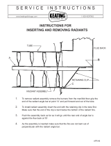
6.5 Radiants installation.
Important: Fit the radiants ensuring that their rear face rests against the horizontal
ribs in the rear panel. There will be a small gap between their bottom front edges and
the retaining channel at the front of the radiant box.
Page 20
© Baxi Heating U.K. Limited 2008.
Figure 12. Upper fixing
brackets.
Figure 11. Wall fixing hole locations
INSTALLER GUIDE
/