Page is loading ...

Replacing Main Unit
RBS 6302
OPERATING INSTRUCTIONS
81/1543-LZA 701 6001 Uen B

Copyright
© Ericsson AB 2012. All rights reserved. No part of this document may be
reproduced in any form without the written permission of the copyright owner.
Disclaimer
The contents of this document are subject to revision without notice due to
continued progress in methodology, design and manufacturing. Ericsson shall
have no liability for any error or damage of any kind resulting from the use
of this document.
Trademark List
All trademarks mentioned herein are the property of their respective owners.
These are shown in the document Trademark Information.
81/1543-LZA 701 6001 Uen B | 2012-11-09

Contents
Contents
1 Introduction 1
1.1 Prerequisites 3
1.2 Warranty Seal 5
2 Replacing the Main Unit 7
2.1 Removing the Main Unit 7
2.2 Installing the Main Unit 34
3 Replacing the GPS Receiver Unit 35
3.1 Removing the GPS Receiver Unit 35
3.2 Installing the GPS Receiver Unit 39
4 Performing Concluding Routines 41
Reference List 43
81/1543-LZA 701 6001 Uen B | 2012-11-09

Replacing Main Unit
81/1543-LZA 701 6001 Uen B | 2012-11-09

Introduction
1 Introduction
This instruction describes how to remove the RBS 6302 main unit and optional
Global Positioning System (GPS) receiver unit, in preparation for installing
replacement units. The main unit removal and subsequent replacement
procedures are ordinarily performed during off-peak hours to minimize traffic
disturbance.
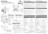
The main unit installation alternatives are presented in Figure 1, and are the
following:
• Single unit on a pole
• Single unit on a wall
• Dual unit back-to-back on a pole
• Dual unit back-to-back on a wall
• Triple unit on a pole
1
81/1543-LZA 701 6001 Uen B | 2012-11-09

Replacing Main Unit
Ge2569A
Figure 1 RBS 6302 Main Unit Installation Alternatives
2
81/1543-LZA 701 6001 Uen B | 2012-11-09

Introduction
1.1 Prerequisites
This section contains information on the documents, tools, and conditions that
apply to the procedures.
Note: Information on compatibility issues can be found in Compatibilities for
Hardware and Software.
1.1.1 Documents
Ensure that the following documents are read and understood:
• Personal Health and Safety Information
• System Safety Information
See Reference List on page 43 for required documents.
3
81/1543-LZA 701 6001 Uen B | 2012-11-09

Replacing Main Unit
1.1.2 Tools
The tools required for replacing the main unit are listed in Table 1.
Table 1 Required Tools
Product Name Product Number Included in
Box socket set with
• Allen key bit, 6 mm
• Torx bit, T20
• FD bit, 5.5 mm
• Socket, 13 mm
LTT 601 138/1
Socket, 16 mm LSB 107 13/1
Torx screwdriver, T10 LSA 901 43/1
Torx screwdriver, T20 LSA 901 43/3
Torx screwdriver, T25 LSA 901 43/4
Tool for cable ties LSD 901 46/1
Extension bar 3/8 inch,
250 mm
LSS 103 29/1
Personal tools light
(LTT 601 156/1)
Electrostatic Discharge
(ESD) wrist strap
LTT 601 136/1
Ferrule end-face
cleaner
LTT 601 154/1
1.1.3 Conditions
Before starting this procedure, ensure that the following conditions are met:
• A work order is available.
• Applicable new units are available.
• If applicable, a client configured to run the RBS Element Manager
(RBS EM) with the relevant Java plug-in version installed, is available.
• If applicable, a new Configuration Version (CV) is loaded.
• All relevant documentation is available.
• All keys are available (including padlock keys for the optional solar shield
padlock), and site access is granted.
4
81/1543-LZA 701 6001 Uen B | 2012-11-09

Introduction
Note: The following precautions must be taken when working at height:
• Wear a safety belt and helmet.
• Wear adequate protective clothing in cold weather.
• Use only tested and approved lifting devices.
1.2 Warranty Seal
The unit is equipped with a warranty seal sticker.
Note: Seals that have been implemented by Ericsson shall not be broken or
removed, as it will otherwise void warranty.
5
81/1543-LZA 701 6001 Uen B | 2012-11-09

Replacing Main Unit
6 81/1543-LZA 701 6001 Uen B | 2012-11-09

Replacing the Main Unit
2 Replacing the Main Unit
This section contains instructions for how to replace a main unit.
Information about compatibilities of hardware and software can be found in
Compatibilities for Hardware and Software.
For WCDMA, it is possible to expand the main unit with a second unit in a dual
unit configuration, where two connected units constitute one RBS. For more
information, see Expanding Configurations.
Note: In a dual unit configuration, only the faulty unit is replaced.
2.1 Removing the Main Unit
The procedures for removing a main unit apply to wall or pole installation.
Removing a faulty main unit implies reinstalling a replacement unit. All
replacement parts are in place in preparation for either wall or pole reinstallation.
Warning!
Risk for falling objects, work at height in progress. Falling objects can cause
serious injury or even be fatal. Always wear a helmet and avoid standing in
the danger area.
Warning!
High energy levels are present in this unit. Improper handling of the unit can
lead to short circuiting that can result in serious injury. Exercise care when
working with this unit.
781/1543-LZA 701 6001 Uen B | 2012-11-09

Replacing Main Unit
Do!
Always use an approved ESD wrist strap when working with sensitive
equipment. Damage to components mounted on printed board assemblies can
occur if an ESD wrist strap is not used.
2.1.1 Preparing Removal
To prepare the main unit for removal, perform the following procedure:
1. Inform the Operation and Maintenance Center (OMC) that work is to start
at the node site. The OMC can then take the affected sectors out of service
to minimize traffic disturbance.
2. If you are ready to install new equipment, check to see that the items
delivered correspond to the packing list. Unpack the replacement unit,
and check to see that it is not damaged. If it is damaged, immediately
report to the transport company. Take a photo of the damage to expedite
the claims process.
Note: Always rest the main unit standing upright on a flat surface or
laying down on its back.
3. Ensure that the old unit has the administrative state locked, if possible.
4. Switch off the main unit's external power (there is no internal power switch
on the main unit).
5. Disconnect the power cable from the main unit or the PSU AC.
Ge2125A
Ge2160A
6. Release the front solar shield by pressing outwards on both rails and slide
the solar shield upwards until it snaps in the upper position.
Note: If the front solar shield is equipped with the padlock option, you
must first unlock it. Put the locks and keys in a pocket or otherwise
secure them if working at height.
8
81/1543-LZA 701 6001 Uen B | 2012-11-09

Replacing the Main Unit
Ge2274A
7. Loosen the four captive screws holding the installation cover using a T20
Torx screwdriver.
Ge2666A
T20 Torx
8. Open the installation cover until it snaps into position, holding the
installation cover open.
9
81/1543-LZA 701 6001 Uen B | 2012-11-09

Replacing Main Unit
Ge2150A
9. Connect the ESD wrist strap to the grounding point on the main unit, as
shown.
Always use the ESD wrist strap when handling cables inside the installation
cover on the main unit.
Ge2363A
10 81/1543-LZA 701 6001 Uen B | 2012-11-09

Replacing the Main Unit
Note: Be careful not to drop any equipment, tools, or screws if you are
working at height. Tools should be secured to belts or harnesses
if working at height.
10. Open the cable gland holding the optical cables.
Note: Ensure that all cables are labeled before disconnecting them.
Ge2667A
11. Remove the optical cables by unplugging them from the Small form Factor
Pluggable (SFP) modules.
Note: Never touch the end face of the optical connectors. Protect from
dirt or grease that can damage fiber optic cables. Too much or
careless bending may damage the cable. The minimum allowed
bending radius can be found in
Installing Optical Cables for
Main-Remote Solutions.
11
81/1543-LZA 701 6001 Uen B | 2012-11-09

Replacing Main Unit
IDL TN B A C
B
DE
F
Ge2668A
12. Cover the optical cables with a plastic bag and clamp or strap the cables
to the pole, or wall.
Note: Do not clamp the cable too tight. Proper handling of optical cables
in main remote systems, can be found in Installing Optical Cables
for Main-Remote Solutions
Ge2732A
13. Open the cable gland holding the electrical cables.
Note: Ensure that all cables are labeled before disconnecting them.
12
81/1543-LZA 701 6001 Uen B | 2012-11-09

Replacing the Main Unit
Ge2669A
14. Loosen the three captive screws holding the shield terminal in place using
a T10 Torx screwdriver.
Ge2672A
T10 Torx
15. Disconnect the electrical transmission cables from the main unit, port TN A,
ET A, and ET B, if applicable.
13
81/1543-LZA 701 6001 Uen B | 2012-11-09

Replacing Main Unit
Ge2670A
GPS EC AUX LMT A LMT B TN A ET A ET B
EC E
SAU
12 34
5
678
!
16. Disconnect the external alarm by removing two socket connectors from
the main unit, if applicable.
Ge2671A
17. Unscrew and disconnect the GPS RF cable, if applicable
14
81/1543-LZA 701 6001 Uen B | 2012-11-09

Replacing the Main Unit
Ge2673A
18. Disconnect the ESD wrist strap from the grounding point on the main unit.
19. Disconnect the ground cable from the main unit using a wrench fitted with a
13 mm socket.
Ge2174A
Socket 13 mm
20. Secure all the cables and the shield terminal. Clamp or strap the cables to
the pole or wall.
Cover the cables connections and the shield terminal with a plastic bag, if
necessary.
15
81/1543-LZA 701 6001 Uen B | 2012-11-09

Replacing Main Unit
Ge2675A
21. Close the installation cover, and tighten the four captive screws to a torque
of 1.7 Nm using a T20 Torx screwdriver.
Ge2155A
1.7 Nm
T20 Torx
22. Close the front solar shield by sliding it down until it snaps into closed
position.
16
81/1543-LZA 701 6001 Uen B | 2012-11-09
/