Page is loading ...

User’s and Installation Guide
Power Xpert™ 9395P UPS
500 kVA / 600 kVA P-164000476

P-164000476 9395P 500kVA / 600 kVA 2
Revision 002 User’s and Installation Guide

P-164000476 9395P 500kVA / 600 kVA 3
Revision 002 User’s and Installation Guide
Power Xpert™ 9395P UPS
500 kVA / 600 kVA
User’s and Installation Guide

P-164000476 9395P 500kVA / 600 kVA 4
Revision 002 User’s and Installation Guide
IMPORTANT SAFETY INSTRUCTIONS
SAVE THESE INSTRUCTIONS
This manual contains important instructions that you should follow during installation and maintenance
of the UPS and batteries. Please read all instructions before operating the equipment and save this
manual for future reference.
This is a product for commercial and industrial application in the second environment.
Installation restrictions or additional measures may be needed to prevent disturbances.
©February 9, 2015 Eaton Corporation
All Rights Reserved
The contents of this manual are the copyright of the publisher and may not be reproduced (even
extracts) unless permission granted.Every care has been taken to ensure the accuracy of the
information contained in this manual, but no liability can be accepted for any errors or omission. The
right to make design modifications is reserved.

P-164000476 9395P 500kVA / 600 kVA i
Revision 002 User’s and Installation Guide
1 Introduction . . . . . . . . . . . . . . . . . . . . . . . . . . . . . . . . . . . . . . . . . . . . . . . . . . . . . . . . . . . . . . . . . . . . . . . . . . . . . . . . . . . . . . . . . . 1
1.1 UPS standard features . . . . . . . . . . . . . . . . . . . . . . . . . . . . . . . . . . . . . . . . . . . . . . . . . . . . . . . . . . . . . . . . . . . . . . . . . . . . . . . 1
1.1.1 Installation features . . . . . . . . . . . . . . . . . . . . . . . . . . . . . . . . . . . . . . . . . . . . . . . . . . . . . . . . . . . . . . . . . . . . . . . . . 1
1.1.2 Control panel. . . . . . . . . . . . . . . . . . . . . . . . . . . . . . . . . . . . . . . . . . . . . . . . . . . . . . . . . . . . . . . . . . . . . . . . . . . . . . . 1
1.1.3 Customer Interface . . . . . . . . . . . . . . . . . . . . . . . . . . . . . . . . . . . . . . . . . . . . . . . . . . . . . . . . . . . . . . . . . . . . . . . . . . 2
1.1.4 Advanced Battery Management . . . . . . . . . . . . . . . . . . . . . . . . . . . . . . . . . . . . . . . . . . . . . . . . . . . . . . . . . . . . . . . . 3
1.1.5 Power Management Software . . . . . . . . . . . . . . . . . . . . . . . . . . . . . . . . . . . . . . . . . . . . . . . . . . . . . . . . . . . . . . . . . 3
1.2 Options and accessories . . . . . . . . . . . . . . . . . . . . . . . . . . . . . . . . . . . . . . . . . . . . . . . . . . . . . . . . . . . . . . . . . . . . . . . . . . . . . . 3
1.2.1 Integrated battery cabinet . . . . . . . . . . . . . . . . . . . . . . . . . . . . . . . . . . . . . . . . . . . . . . . . . . . . . . . . . . . . . . . . . . . . 3
1.2.2 Field Installed UPM. . . . . . . . . . . . . . . . . . . . . . . . . . . . . . . . . . . . . . . . . . . . . . . . . . . . . . . . . . . . . . . . . . . . . . . . . . 3
1.2.3 Sync Control . . . . . . . . . . . . . . . . . . . . . . . . . . . . . . . . . . . . . . . . . . . . . . . . . . . . . . . . . . . . . . . . . . . . . . . . . . . . . . . 3
1.2.4 Single-feed kit. . . . . . . . . . . . . . . . . . . . . . . . . . . . . . . . . . . . . . . . . . . . . . . . . . . . . . . . . . . . . . . . . . . . . . . . . . . . . . 3
1.2.5 Separate rectifier input (factory-installed option) . . . . . . . . . . . . . . . . . . . . . . . . . . . . . . . . . . . . . . . . . . . . . . . . . . 3
1.2.6 Distributed Bypass System . . . . . . . . . . . . . . . . . . . . . . . . . . . . . . . . . . . . . . . . . . . . . . . . . . . . . . . . . . . . . . . . . . . . 4
1.2.7 Input Output Module configuration . . . . . . . . . . . . . . . . . . . . . . . . . . . . . . . . . . . . . . . . . . . . . . . . . . . . . . . . . . . . . 4
1.2.8 Inherent redundancy . . . . . . . . . . . . . . . . . . . . . . . . . . . . . . . . . . . . . . . . . . . . . . . . . . . . . . . . . . . . . . . . . . . . . . . . . 4
1.2.9 Energy Saver and High Alert modes . . . . . . . . . . . . . . . . . . . . . . . . . . . . . . . . . . . . . . . . . . . . . . . . . . . . . . . . . . . . . 4
1.2.10 Variable Module Management System and High Alert modes . . . . . . . . . . . . . . . . . . . . . . . . . . . . . . . . . . . . . . . . 5
1.2.11 Optional X-Slot cards . . . . . . . . . . . . . . . . . . . . . . . . . . . . . . . . . . . . . . . . . . . . . . . . . . . . . . . . . . . . . . . . . . . . . . . . 5
1.3 Basic system configurations . . . . . . . . . . . . . . . . . . . . . . . . . . . . . . . . . . . . . . . . . . . . . . . . . . . . . . . . . . . . . . . . . . . . . . . . . . . 5
1.4 Using this manual . . . . . . . . . . . . . . . . . . . . . . . . . . . . . . . . . . . . . . . . . . . . . . . . . . . . . . . . . . . . . . . . . . . . . . . . . . . . . . . . . . . 6
1.5 Conventions used in this manual . . . . . . . . . . . . . . . . . . . . . . . . . . . . . . . . . . . . . . . . . . . . . . . . . . . . . . . . . . . . . . . . . . . . . . . 6
1.6 Symbols, controls, and indicators. . . . . . . . . . . . . . . . . . . . . . . . . . . . . . . . . . . . . . . . . . . . . . . . . . . . . . . . . . . . . . . . . . . . . . . 6
1.7 For more information. . . . . . . . . . . . . . . . . . . . . . . . . . . . . . . . . . . . . . . . . . . . . . . . . . . . . . . . . . . . . . . . . . . . . . . . . . . . . . . . . 7
1.8 Getting help. . . . . . . . . . . . . . . . . . . . . . . . . . . . . . . . . . . . . . . . . . . . . . . . . . . . . . . . . . . . . . . . . . . . . . . . . . . . . . . . . . . . . . . . 7
2 Safety warnings. . . . . . . . . . . . . . . . . . . . . . . . . . . . . . . . . . . . . . . . . . . . . . . . . . . . . . . . . . . . . . . . . . . . . . . . . . . . . . . . . . . . . . . 9
3 UPS installation plan and unpacking . . . . . . . . . . . . . . . . . . . . . . . . . . . . . . . . . . . . . . . . . . . . . . . . . . . . . . . . . . . . . . . . . . . 11
3.1 Creating an installation plan. . . . . . . . . . . . . . . . . . . . . . . . . . . . . . . . . . . . . . . . . . . . . . . . . . . . . . . . . . . . . . . . . . . . . . . . . . 11
3.2 Preparing the site . . . . . . . . . . . . . . . . . . . . . . . . . . . . . . . . . . . . . . . . . . . . . . . . . . . . . . . . . . . . . . . . . . . . . . . . . . . . . . . . . . 11
3.2.1 Environmental and installation considerations . . . . . . . . . . . . . . . . . . . . . . . . . . . . . . . . . . . . . . . . . . . . . . . . . . . 12
3.2.2 UPS system power wiring preparation . . . . . . . . . . . . . . . . . . . . . . . . . . . . . . . . . . . . . . . . . . . . . . . . . . . . . . . . . . 18
3.2.3 UPS system interface wiring preparation. . . . . . . . . . . . . . . . . . . . . . . . . . . . . . . . . . . . . . . . . . . . . . . . . . . . . . . . 23
3.2.4 Distributed bypass power wiring preparation . . . . . . . . . . . . . . . . . . . . . . . . . . . . . . . . . . . . . . . . . . . . . . . . . . . . 24
3.3 Inspecting and unpacking the UPS cabinet . . . . . . . . . . . . . . . . . . . . . . . . . . . . . . . . . . . . . . . . . . . . . . . . . . . . . . . . . . . . . . 25
4 UPS system installation . . . . . . . . . . . . . . . . . . . . . . . . . . . . . . . . . . . . . . . . . . . . . . . . . . . . . . . . . . . . . . . . . . . . . . . . . . . . . . . 28
4.1 Preliminary installation information . . . . . . . . . . . . . . . . . . . . . . . . . . . . . . . . . . . . . . . . . . . . . . . . . . . . . . . . . . . . . . . . . . . . 28
4.2 Unloading the UPS cabinet from the pallet and mechanical installation . . . . . . . . . . . . . . . . . . . . . . . . . . . . . . . . . . . . . . . 28
4.3 Field installed UPM (FI-UPM) installation. . . . . . . . . . . . . . . . . . . . . . . . . . . . . . . . . . . . . . . . . . . . . . . . . . . . . . . . . . . . . . . . 32
4.4 Battery cabinet installation. . . . . . . . . . . . . . . . . . . . . . . . . . . . . . . . . . . . . . . . . . . . . . . . . . . . . . . . . . . . . . . . . . . . . . . . . . . 32
4.5 Distributed bypass tie cabinet installation. . . . . . . . . . . . . . . . . . . . . . . . . . . . . . . . . . . . . . . . . . . . . . . . . . . . . . . . . . . . . . . 32
4.6 Installing UPS external and battery power wiring . . . . . . . . . . . . . . . . . . . . . . . . . . . . . . . . . . . . . . . . . . . . . . . . . . . . . . . . . 34
4.6.1 External power wiring installation . . . . . . . . . . . . . . . . . . . . . . . . . . . . . . . . . . . . . . . . . . . . . . . . . . . . . . . . . . . . . 34
4.6.2 Battery wiring . . . . . . . . . . . . . . . . . . . . . . . . . . . . . . . . . . . . . . . . . . . . . . . . . . . . . . . . . . . . . . . . . . . . . . . . . . . . . 40
4.7 Installing interface connections . . . . . . . . . . . . . . . . . . . . . . . . . . . . . . . . . . . . . . . . . . . . . . . . . . . . . . . . . . . . . . . . . . . . . . . 41
4.7.1 TB1, TB2, and TB3 connections (other than TB1 battery interface connections). . . . . . . . . . . . . . . . . . . . . . . . . . 41
4.7.2 TB1 battery interface connections . . . . . . . . . . . . . . . . . . . . . . . . . . . . . . . . . . . . . . . . . . . . . . . . . . . . . . . . . . . . . 47
4.7.3 X-Slot connections . . . . . . . . . . . . . . . . . . . . . . . . . . . . . . . . . . . . . . . . . . . . . . . . . . . . . . . . . . . . . . . . . . . . . . . . . 48
4.8 Installing a remote EPO switch. . . . . . . . . . . . . . . . . . . . . . . . . . . . . . . . . . . . . . . . . . . . . . .
. . . . . . . . . . . . . . . . . . . . . . . . . 50
4.9 Installing options, accessories, and distributed bypass control wiring . . . . . . . . . . . . . . . . . . . . . . . . . . . . . . . . . . . . . . . . . 53
4.10 Initial startup. . . . . . . . . . . . . . . . . . . . . . . . . . . . . . . . . . . . . . . . . . . . . . . . . . . . . . . . . . . . . . . . . . . . . . . . . . . . . . . . . . . . . . 53
4.11 Completing the installation checklist . . . . . . . . . . . . . . . . . . . . . . . . . . . . . . . . . . . . . . . . . . . . . . . . . . . . . . . . . . . . . . . . . . . 53
5 Installing options and accessories . . . . . . . . . . . . . . . . . . . . . . . . . . . . . . . . . . . . . . . . . . . . . . . . . . . . . . . . . . . . . . . . . . . . . 54
5.1 Installing an optional HotSync CAN Bridge Card . . . . . . . . . . . . . . . . . . . . . . . . . . . . . . . . . . . . . . . . . . . . . . . . . . . . . . . . . . 54
5.2 Installing distributed bypass control wiring . . . . . . . . . . . . . . . . . . . . . . . . . . . . . . . . . . . . . . . . . . . . . . . . . . . . . . . . . . . . . . 56
6 Understanding UPS operation. . . . . . . . . . . . . . . . . . . . . . . . . . . . . . . . . . . . . . . . . . . . . . . . . . . . . . . . . . . . . . . . . . . . . . . . . . 61
6.1 Looking inside the UPS system. . . . . . . . . . . . . . . . . . . . . . . . . . . . . . . . . . . . . . . . . . . . . . . . . . . . . . . . . . . . . . . . . . . . . . . . 61
6.2 Single UPS. . . . . . . . . . . . . . . . . . . . . . . . . . . . . . . . . . . . . . . . . . . . . . . . . . . . . . . . . . . . . . . . . . . . . . . . . . . . . . . . . . . . . . . . 62
6.2.1 Modes . . . . . . . . . . . . . . . . . . . . . . . . . . . . . . . . . . . . . . . . . . . . . . . . . . . . . . . . . . . . . . . . . . . . . . . . . . . . . . . . . . . 62
6.2.2 Normal mode. . . . . . . . . . . . . . . . . . . . . . . . . . . . . . . . . . . . . . . . . . . . . . . . . . . . . . . . . . . . . . . . . . . . . . . . . . . . . . 62
6.2.3 Bypass mode . . . . . . . . . . . . . . . . . . . . . . . . . . . . . . . . . . . . . . . . . . . . . . . . . . . . . . . . . . . . . . . . . . . . . . . . . . . . . . 64
6.2.4 Variable Module Management System . . . . . . . . . . . . . . . . . . . . . . . . . . . . . . . . . . . . . . . . . . . . . . . . . . . . . . . . . 65
6.2.5 Energy Saver System (ESS). . . . . . . . . . . . . . . . . . . . . . . . . . . . . . . . . . . . . . . . . . . . . . . . . . . . . . . . . . . . . . . . . . . 65
6.2.6 Battery mode. . . . . . . . . . . . . . . . . . . . . . . . . . . . . . . . . . . . . . . . . . . . . . . . . . . . . . . . . . . . . . . . . . . . . . . . . . . . . . 66
6.3 UPS system oneline configurations . . . . . . . . . . . . . . . . . . . . . . . . . . . . . . . . . . . . . . . . . . . . . . . . . . . . . . . . . . . . . . . . . . . . 68
6.4 Multiple UPS distributed bypass system . . . . . . . . . . . . . . . . . . . . . . . . . . . . . . . . . . . . . . . . . . . . . . . . . . . . . . . . . . . . . . . . 74
6.4.1 Multiple UPS parallel system modes . . . . . . . . . . . . . . . . . . . . . . . . . . . . . . . . . . . . . . . . . . . . . . . . . . . . . . . . . . . 74

P-164000476 9395P 500kVA / 600 kVA ii
Revision 002 User’s and Installation Guide
6.4.2 Normal mode – distributed bypass. . . . . . . . . . . . . . . . . . . . . . . . . . . . . . . . . . . . . . . . . . . . . . . . . . . . . . . . . . . . . 75
6.4.3 Bypass mode – distributed bypass . . . . . . . . . . . . . . . . . . . . . . . . . . . . . . . . . . . . . . . . . . . . . . . . . . . . . . . . . . . . . 76
6.4.4 Battery mode – distributed bypass. . . . . . . . . . . . . . . . . . . . . . . . . . . . . . . . . . . . . . . . . . . . . . . . . . . . . . . . . . . . . 77
6.5 Multiple UPS distributed bypass system oneline configurations. . . . . . . . . . . . . . . . . . . . . . . . . . . . . . . . . . . . . . . . . . . . . . 78
7 UPS operating instructions . . . . . . . . . . . . . . . . . . . . . . . . . . . . . . . . . . . . . . . . . . . . . . . . . . . . . . . . . . . . . . . . . . . . . . . . . . . . 82
7.1 UPS controls and indicators . . . . . . . . . . . . . . . . . . . . . . . . . . . . . . . . . . . . . . . . . . . . . . . . . . . . . . . . . . . . . . . . . . . . . . . . . . 82
7.1.1 Control panel. . . . . . . . . . . . . . . . . . . . . . . . . . . . . . . . . . . . . . . . . . . . . . . . . . . . . . . . . . . . . . . . . . . . . . . . . . . . . . 83
7.1.2 Circuit breakers . . . . . . . . . . . . . . . . . . . . . . . . . . . . . . . . . . . . . . . . . . . . . . . . . . . . . . . . . . . . . . . . . . . . . . . . . . . . 83
7.2 Color Touchscreen Control Panel . . . . . . . . . . . . . . . . . . . . . . . . . . . . . . . . . . . . . . . . . . . . . . . . . . . . . . . . . . . . . . . . . . . . . . 84
7.3 Using the Color Touchscreen Control Panel . . . . . . . . . . . . . . . . . . . . . . . . . . . . . . . . . . . . . . . . . . . . . . . . . . . . . . . . . . . . . 85
7.3.1 Status Indicators . . . . . . . . . . . . . . . . . . . . . . . . . . . . . . . . . . . . . . . . . . . . . . . . . . . . . . . . . . . . . . . . . . . . . . . . . . . 85
7.3.2 Using the Touch Screen . . . . . . . . . . . . . . . . . . . . . . . . . . . . . . . . . . . . . . . . . . . . . . . . . . . . . . . . . . . . . . . . . . . . . 86
7.3.3 Using the Main Menu Buttons . . . . . . . . . . . . . . . . . . . . . . . . . . . . . . . . . . . . . . . . . . . . . . . . . . . . . . . . . . . . . . . . 87
7.3.4 Power Maps Screen (Online Mode) . . . . . . . . . . . . . . . . . . . . . . . . . . . . . . . . . . . . . . . . . . . . . . . . . . . . . . . . . . . . 88
7.3.5 Power Maps Screen (Bypass Mode). . . . . . . . . . . . . . . . . . . . . . . . . . . . . . . . . . . . . . . . . . . . . . . . . . . . . . . . . . . . 90
7.3.6 Command Confirmation Pop-Up . . . . . . . . . . . . . . . . . . . . . . . . . . . . . . . . . . . . . . . . . . . . . . . . . . . . . . . . . . . . . . . 90
7.3.7 Meters Summary Screen . . . . . . . . . . . . . . . . . . . . . . . . . . . . . . . . . . . . . . . . . . . . . . . . . . . . . . . . . . . . . . . . . . . . 91
7.3.8 Input Meters Screen . . . . . . . . . . . . . . . . . . . . . . . . . . . . . . . . . . . . . . . . . . . . . . . . . . . . . . . . . . . . . . . . . . . . . . . . 91
7.3.9 Input Meters Detail Screen. . . . . . . . . . . . . . . . . . . . . . . . . . . . . . . . . . . . . . . . . . . . . . . . . . . . . . . . . . . . . . . . . . . 93
7.3.10 Battery Meters Screens . . . . . . . . . . . . . . . . . . . . . . . . . . . . . . . . . . . . . . . . . . . . . . . . . . . . . . . . . . . . . . . . . . . . . 93
7.3.11 System Events Main Screen . . . . . . . . . . . . . . . . . . . . . . . . . . . . . . . . . . . . . . . . . . . . . . . . . . . . . . . . . . . . . . . . . . 95
7.3.12 User Log . . . . . . . . . . . . . . . . . . . . . . . . . . . . . . . . . . . . . . . . . . . . . . . . . . . . . . . . . . . . . . . . . . . . . . . . . . . . . . . . . 95
7.3.13 System Status Screen and Controls . . . . . . . . . . . . . . . . . . . . . . . . . . . . . . . . . . . . . . . . . . . . . . . . . . . . . . . . . . . . 96
7.3.14 Settings Screen. . . . . . . . . . . . . . . . . . . . . . . . . . . . . . . . . . . . . . . . . . . . . . . . . . . . . . . . . . . . . . . . . . . . . . . . . . . . 99
7.3.15 Configuration Options Screen. . . . . . . . . . . . . . . . . . . . . . . . . . . . . . . . . . . . . . . . . . . . . . . . . . . . . . . . . . . . . . . . . 99
7.3.16 Energy Advantage Architecture (EAA) Screen . . . . . . . . . . . . . . . . . . . . . . . . . . . . . . . . . . . . . . . . . . . . . . . . . . . 100
7.3.17 Statistics Basic Screen . . . . . . . . . . . . . . . . . . . . . . . . . . . . . . . . . . . . . . . . . . . . . . . . . . . . . . . . . . . . . . . . . . . . . 101
7.3.18 ESS Comparison Screen . . . . . . . . . . . . . . . . . . . . . . . . . . . . . . . . . . . . . . . . . . . . . . . . . . . . . . . . . . . . . . . . . . . . 102
7.3.19 UPS Module Map Screen . . . . . . . . . . . . . . . . . . . . . . . . . . . . . . . . . . . . . . . . . . . . . . . . . . . . . . . . . . . . . . . . . . . 103
7.3.20 System Overview Screen . . . . . . . . . . . . . . . . . . . . . . . . . . . . . . . . . . . . . . . . . . . . . . . . . . . . . . . . . . . . . . . . . . . 103
7.4 UPS Operation using the Color Touchscreen Control Panel . . . . . . . . . . . . . . . . . . . . . . . . . . . . . . . . . . . . . . . . . . . . . . . . . 104
7.4.1 Starting the UPS in Online mode . . . . . . . . . . . . . . . . . . . . . . . . . . . . . . . . . . . . . . . . . . . . . . . . . . . . . . . . . . . . . 104
7.4.2 Starting the UPS in Bypass mode . . . . . . . . . . . . . . . . . . . . . . . . . . . . . . . . . . . . . . . . . . . . . . . . . . . . . . . . . . . . . 105
7.4.3 Starting the UPMs. . . . . . . . . . . . . . . . . . . . . . . . . . . . . . . . . . . . . . . . . . . . . . . . . . . . . . . . . . . . . . . . . . . . . . . . . 105
7.4.4 Starting a single UPM. . . . . . . . . . . . . . . . . . . . . . . . . . . . . . . . . . . . . . . . . . . . . . . . . . . . . . . . . . . . . . . . . . . . . . 106
7.4.5 Enable Variable Module Management System mode from the EEA controls menu . . . . . . . . . . . . . . . . . . . . . . 106
7.4.6 Disable Variable Module Management System mode from the EEA controls menu . . . . . . . . . . . . . . . . . . . . . 107
7.4.7 Start Variable Module Management System High Alert mode from the EEA controls menu . . . . . . . . . . . . . . . 107
7.4.8 Transfer from Normal to Bypass mode. . . . . . . . . . . . . . . . . . . . . . . . . . . . . . . . . . . . . . . . . . . . . . . . . . . . . . . . . 108
7.4.9 Transfer from Bypass to Normal mode. . . . . . . . . . . . . . . . . . . . . . . . . . . . . . . . . . . . . . . . . . . . . . . . . . . . . . . . . 108
7.4.10 Enable Energy Saver System from EAA Controls menu . . . . . . . . . . . . . . . . . . . . . . . . . . . . . . . . . . . . . . . . . . . . 108
7.4.11 Disable Energy Saver System from EAA Controls menu . . . . . . . . . . . . . . . . . . . . . . . . . . . . . . . . . . . . . . . . . . . 109
7.4.12 Transfer from Energy Saver System to Bypass mode. . . . . . . . . . . . . . . . . . . . . . . . . . . . . . . . . . . . . . . . . . . . . . 109
7.4.13 Transfer from Normal to Bypass mode and shut down UPS . . . . . . . . . . . . . . . . . . . . . . . . . . . . . . . . . . . . . . . . 110
7.4.14 Single UPM shutdown . . . . . . . . . . . . . . . . . . . . . . . . . . . . . . . . . . . . . . . . . . . . . . . . . . . . . . . . . . . . . . . . . . . . . 110
7.4.15 Single UPM restart . . . . . . . . . . . . . . . . . . . . . . . . . . . . . . . . . . . . . . . . . . . . . . . . . . . . . . . . . . . . . . . . . . . . . . . . 110
7.4.16 UPS and critical load shutdown . . . . . . . . . . . . . . . . . . . . . . . . . . . . . . . . . . . . . . . . . . . . . . . . . . . . . . . . . . . . . . 110
7.4.17 Charger control . . . . . . . . . . . . . . . . . . . . . . . . . . . . . . . . . . . . . . . . . . . . . . . . . . . . . . . . . . . . . . . . . . . . . . . . . . . 111
7.4.18 Using the UPS LOAD OFF . . . . . . . . . . . . . . . . . . . . . . . . . . . . . . . . . . . . . . . . . . . . . . . . . . . . . . . . . . . . . . . . . . . 111
7.4.19 Using the Remote Emergency Power-off switch . . . . . . . . . . . . . . . . . . . . . . . . . . . . . . . . . . . . . . .
. . . . . . . . . . 112
7.4.20 Using Mechanical Bypass Switch. . . . . . . . . . . . . . . . . . . . . . . . . . . . . . . . . . . . . . . . . . . . . . . . . . . . . . . . . . . . . 112
7.5 Multiple UPS distributed bypass operation . . . . . . . . . . . . . . . . . . . . . . . . . . . . . . . . . . . . . . . . . . . . . . . . . . . . . . . . . . . . . 115
7.5.1 Starting the distributed bypass system in normal mode . . . . . . . . . . . . . . . . . . . . . . . . . . . . . . . . . . . . . . . . . . . 115
7.5.2 Starting the distributed bypass system in Bypass mode . . . . . . . . . . . . . . . . . . . . . . . . . . . . . . . . . . . . . . . . . . . 115
7.5.3 Enable Variable Module Management System mode from the EEA controls menu . . . . . . . . . . . . . . . . . . . . . . 116
7.5.4 Disable Variable Module Management System mode from the EEA controls menu . . . . . . . . . . . . . . . . . . . . . 116
7.5.5 How to start High Alert Timer from the EAA Controls menu . . . . . . . . . . . . . . . . . . . . . . . . . . . . . . . . . . . . . . . . 116
7.5.6 Starting the UPS UPMs. . . . . . . . . . . . . . . . . . . . . . . . . . . . . . . . . . . . . . . . . . . . . . . . . . . . . . . . . . . . . . . . . . . . . 116
7.5.7 Starting a single UPM. . . . . . . . . . . . . . . . . . . . . . . . . . . . . . . . . . . . . . . . . . . . . . . . . . . . . . . . . . . . . . . . . . . . . . 117
7.5.8 Transfer from Normal to Bypass mode. . . . . . . . . . . . . . . . . . . . . . . . . . . . . . . . . . . . . . . . . . . . . . . . . . . . . . . . . 117
7.5.9 Transfer from Bypass to Normal mode. . . . . . . . . . . . . . . . . . . . . . . . . . . . . . . . . . . . . . . . . . . . . . . . . . . . . . . . . 118
7.5.10 Enable Energy Saver System from EAA Controls menu . . . . . . . . . . . . . . . . . . . . . . . . . . . . . . . . . . . . . . . . . . . . 118
7.5.11 Disable Energy Saver System from EAA Controls menu . . . . . . . . . . . . . . . . . . . . . . . . . . . . . . . . . . . . . . . . . . . 118
7.5.12 Transfer from Energy Saver System to Bypass mode. . . . . . . . . . . . . . . . . . . . . . . . . . . . . . . . . . . . . . . . . . . . . . 119
7.5.13 Transfer from Normal to Bypass mode and shut down all UPMs . . . . . . . . . . . . . . . . . . . . . . . . . . . . . . . . . . . . 119
7.5.14 Single UPM shutdown . . . . . . . . . . . . . . . . . . . . . . . . . . . . . . . . . . . . . . . . . . . . . . . . . . . . . . . . . . . . . . . . . . . . . 119
7.5.15 Single UPM restart . . . . . . . . . . . . . . . . . . . . . . . . . . . . . . . . . . . . . . . . . . . . . . . . . . . . . . . . . . . . . . . . . . . . . . . . 120
7.5.16 Single UPS shutdown using load off . . . . . . . . . . . . . . . . . . . . . . . . . . . . . . . . . . . . . . . . . . . . . . . . . . . . . . . . . . 120
7.5.17 Single UPS shutdown using UPM shutdown . . . . . . . . . . . . . . . . . . . . . . . . . . . . . . . . . . . . . . . . . . . . . . . . . . . . 121

P-164000476 9395P 500kVA / 600 kVA iii
Revision 002 User’s and Installation Guide
7.5.18 Single UPS restart. . . . . . . . . . . . . . . . . . . . . . . . . . . . . . . . . . . . . . . . . . . . . . . . . . . . . . . . . . . . . . . . . . . . . . . . . 122
7.5.19 UPS and critical load shutdown . . . . . . . . . . . . . . . . . . . . . . . . . . . . . . . . . . . . . . . . . . . . . . . . . . . . . . . . . . . . . . 123
7.5.20 Charger control . . . . . . . . . . . . . . . . . . . . . . . . . . . . . . . . . . . . . . . . . . . . . . . . . . . . . . . . . . . . . . . . . . . . . . . . . . . 123
7.5.21 Using the UPS LOAD OFF . . . . . . . . . . . . . . . . . . . . . . . . . . . . . . . . . . . . . . . . . . . . . . . . . . . . . . . . . . . . . . . . . . . 123
7.5.22 Using the Remote Emergency Power-off Switch . . . . . . . . . . . . . . . . . . . . . . . . . . . . . . . . . . . . . . . . . . . . . . . . . 124
8 Communication . . . . . . . . . . . . . . . . . . . . . . . . . . . . . . . . . . . . . . . . . . . . . . . . . . . . . . . . . . . . . . . . . . . . . . . . . . . . . . . . . . . . . 126
8.1 X-Slot cards. . . . . . . . . . . . . . . . . . . . . . . . . . . . . . . . . . . . . . . . . . . . . . . . . . . . . . . . . . . . . . . . . . . . . . . . . . . . . . . . . . . . . . 126
8.2 LanSafe Power Management Software . . . . . . . . . . . . . . . . . . . . . . . . . . . . . . . . . . . . . . . . . . . . . . . . . . . . . . . . . . . . . . . . 127
8.3 Terminal mode . . . . . . . . . . . . . . . . . . . . . . . . . . . . . . . . . . . . . . . . . . . . . . . . . . . . . . . . . . . . . . . . . . . . . . . . . . . . . . . . . . . 127
8.3.1 Display UPS control panel. . . . . . . . . . . . . . . . . . . . . . . . . . . . . . . . . . . . . . . . . . . . . . . . . . . . . . . . . . . . . . . . . . . 128
8.3.2 Event History Log . . . . . . . . . . . . . . . . . . . . . . . . . . . . . . . . . . . . . . . . . . . . . . . . . . . . . . . . . . . . . . . . . . . . . . . . . 128
8.4 Building alarm monitoring. . . . . . . . . . . . . . . . . . . . . . . . . . . . . . . . . . . . . . . . . . . . . . . . . . . . . . . . . . . . . . . . . . . . . . . . . . . 130
8.5 General purpose relay contact . . . . . . . . . . . . . . . . . . . . . . . . . . . . . . . . . . . . . . . . . . . . . . . . . . . . . . . . . . . . . . . . . . . . . . . 130
9 UPS maintenance . . . . . . . . . . . . . . . . . . . . . . . . . . . . . . . . . . . . . . . . . . . . . . . . . . . . . . . . . . . . . . . . . . . . . . . . . . . . . . . . . . . 131
9.1 Important safety instructions . . . . . . . . . . . . . . . . . . . . . . . . . . . . . . . . . . . . . . . . . . . . . . . . . . . . . . . . . . . . . . . . . . . . . . . . 131
9.2 Performing preventive maintenance. . . . . . . . . . . . . . . . . . . . . . . . . . . . . . . . . . . . . . . . . . . . . . . . . . . . . . . . . . . . . . . . . . . 132
9.2.1 DAILY maintenance. . . . . . . . . . . . . . . . . . . . . . . . . . . . . . . . . . . . . . . . . . . . . . . . . . . . . . . . . . . . . . . . . . . . . . . . 132
9.2.2 MONTHLY maintenance . . . . . . . . . . . . . . . . . . . . . . . . . . . . . . . . . . . . . . . . . . . . . . . . . . . . . . . . . . . . . . . . . . . . 132
9.2.3 PERIODIC maintenance . . . . . . . . . . . . . . . . . . . . . . . . . . . . . . . . . . . . . . . . . . . . . . . . . . . . . . . . . . . . . . . . . . . . . 132
9.2.4 ANNUAL maintenance . . . . . . . . . . . . . . . . . . . . . . . . . . . . . . . . . . . . . . . . . . . . . . . . . . . . . . . . . . . . . . . . . . . . . 132
9.2.5 BATTERY maintenance . . . . . . . . . . . . . . . . . . . . . . . . . . . . . . . . . . . . . . . . . . . . . . . . . . . . . . . . . . . . . . . . . . . . . 132
9.3 Installing batteries . . . . . . . . . . . . . . . . . . . . . . . . . . . . . . . . . . . . . . . . . . . . . . . . . . . . . . . . . . . . . . . . . . . . . . . . . . . . . . . . 133
9.4 Recycling the used UPS or batteries. . . . . . . . . . . . . . . . . . . . . . . . . . . . . . . . . . . . . . . . . . . . . . . . . . . . . . . . . . . . . . . . . . . 133
9.5 Maintenance training . . . . . . . . . . . . . . . . . . . . . . . . . . . . . . . . . . . . . . . . . . . . . . . . . . . . . . . . . . . . . . . . . . . . . . . . . . . . . . 133
10 Product specifications . . . . . . . . . . . . . . . . . . . . . . . . . . . . . . . . . . . . . . . . . . . . . . . . . . . . . . . . . . . . . . . . . . . . . . . . . . . . . . . 134
10.1 Model numbers . . . . . . . . . . . . . . . . . . . . . . . . . . . . . . . . . . . . . . . . . . . . . . . . . . . . . . . . . . . . . . . . . . . . . . . . . . . . . . . . . . . 134
10.2 Single module specifications . . . . . . . . . . . . . . . . . . . . . . . . . . . . . . . . . . . . . . . . . . . . . . . . . . . . . . . . . . . . . . . . . . . . . . . . 134
10.2.1 UPS system input . . . . . . . . . . . . . . . . . . . . . . . . . . . . . . . . . . . . . . . . . . . . . . . . . . . . . . . . . . . . . . . . . . . . . . . . . 134
10.2.2 UPS system output . . . . . . . . . . . . . . . . . . . . . . . . . . . . . . . . . . . . . . . . . . . . . . . . . . . . . . . . . . . . . . . . . . . . . . . . 134
10.2.3 Environmental . . . . . . . . . . . . . . . . . . . . . . . . . . . . . . . . . . . . . . . . . . . . . . . . . . . . . . . . . . . . . . . . . . . . . . . . . . . . 135
11 Warranty . . . . . . . . . . . . . . . . . . . . . . . . . . . . . . . . . . . . . . . . . . . . . . . . . . . . . . . . . . . . . . . . . . . . . . . . . . . . . . . . . . . . . . . . . . . 136
12 Installation checklist . . . . . . . . . . . . . . . . . . . . . . . . . . . . . . . . . . . . . . . . . . . . . . . . . . . . . . . . . . . . . . . . . . . . . . . . . . . . . . . . 137

P-164000476 9395P 500kVA / 600 kVA iv
Revision 002 User’s and Installation Guide
List of Tables
Table 3-1: UPS cabinet weights . . . . . . . . . . . . . . . . . . . . . . . . . . . . . . . . . . . . . . . . . . . . . . . . . . . . . . . . . . . . . . . . . . . . . . . . . . . . . . . . . . . . . . . 12
Table 3-2: UPS cabinet clearances . . . . . . . . . . . . . . . . . . . . . . . . . . . . . . . . . . . . . . . . . . . . . . . . . . . . . . . . . . . . . . . . . . . . . . . . . . . . . . . . . . . . . 12
Table 3-3: Air conditioning or ventilation requirements during full load operation. . . . . . . . . . . . . . . . . . . . . . . . . . . . . . . . . . . . . . . . . . . . . . . . 13
Table 3-4: Input/output rating for 9395P 500 kVA / 600 kVA. . . . . . . . . . . . . . . . . . . . . . . . . . . . . . . . . . . . . . . . . . . . . . . . . . . . . . . . . . . . . . . . . 18
Table 3-5: Separate rectifier input UPM ratings and external wiring requirements for the 9395P 500 kVA / 600 kVA. . . . . . . . . . . . . . . . . . . . 19
Table 5-6: UPS cabinet power cable terminations for the 9395P 500 kVA / 600 kVA . . . . . . . . . . . . . . . . . . . . . . . . . . . . . . . . . . . . . . . . . . . . . 20
Table 5-7: Recommended installation parts (not supplied by Eaton Corporation). . . . . . . . . . . . . . . . . . . . . . . . . . . . . . . . . . . . . . . . . . . . . . . . . 21
Table 5-8: Recommended input circuit breaker ratings . . . . . . . . . . . . . . . . . . . . . . . . . . . . . . . . . . . . . . . . . . . . . . . . . . . . . . . . . . . . . . . . . . . . . 21
Table 5-9: Recommended bypass and output circuit breaker ratings . . . . . . . . . . . . . . . . . . . . . . . . . . . . . . . . . . . . . . . . . . . . . . . . . . . . . . . . . . 22
Table 5-10: Recommended DC input circuit breaker ratings . . . . . . . . . . . . . . . . . . . . . . . . . . . . . . . . . . . . . . . . . . . . . . . . . . . . . . . . . . . . . . . . . 22
Table 4-1: TB1, TB2, and TB3 interface connections . . . . . . . . . . . . . . . . . . . . . . . . . . . . . . . . . . . . . . . . . . . . . . . . . . . . . . . . . . . . . . . . . . . . . . . 47
Table 4-2: Remote EPO wire terminations . . . . . . . . . . . . . . . . . . . . . . . . . . . . . . . . . . . . . . . . . . . . . . . . . . . . . . . . . . . . . . . . . . . . . . . . . . . . . . . 51
Table 5-1: HotSync CAN Bridge Card interface connections . . . . . . . . . . . . . . . . . . . . . . . . . . . . . . . . . . . . . . . . . . . . . . . . . . . . . . . . . . . . . . . . . 55
Table 5-2: CAN Bridge Card wiring terminations . . . . . . . . . . . . . . . . . . . . . . . . . . . . . . . . . . . . . . . . . . . . . . . . . . . . . . . . . . . . . . . . . . . . . . . . . . 58
Table 5-3: Pull-Chain wiring terminations . . . . . . . . . . . . . . . . . . . . . . . . . . . . . . . . . . . . . . . . . . . . . . . . . . . . . . . . . . . . . . . . . . . . . . . . . . . . . . . 58
Table 5-4: Pull-Chain wiring terminations with MOBs. . . . . . . . . . . . . . . . . . . . . . . . . . . . . . . . . . . . . . . . . . . . . . . . . . . . . . . . . . . . . . . . . . . . . . 60
Table 7-1: Status Indicators . . . . . . . . . . . . . . . . . . . . . . . . . . . . . . . . . . . . . . . . . . . . . . . . . . . . . . . . . . . . . . . . . . . . . . . . . . . . . . . . . . . . . . . . . . 86
Table 7-2: Security Levels and Functions . . . . . . . . . . . . . . . . . . . . . . . . . . . . . . . . . . . . . . . . . . . . . . . . . . . . . . . . . . . . . . . . . . . . . . . . . . . . . . . . 87
Table 7-3: Display Function Menu Map . . . . . . . . . . . . . . . . . . . . . . . . . . . . . . . . . . . . . . . . . . . . . . . . . . . . . . . . . . . . . . . . . . . . . . . . . . . . . . . . . 88

P-164000476 9395P 500kVA / 600 kVA v
Revision 002 User’s and Installation Guide
List of Figures
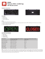
Figure 1-1. UPS (500 kVA / 600 kVA) with the 7-inch color touchscreen. . . . . . . . . . . . . . . . . . . . . . . . . . . . . . . . . . . . . . . . . . . . . . . . . . . . . . . . . 2
Figure 3-1. UPS cabinet dimensions (front view) . . . . . . . . . . . . . . . . . . . . . . . . . . . . . . . . . . . . . . . . . . . . . . . . . . . . . . . . . . . . . . . . . . . . . . . . . . 13
Figure 3-2. UPS cabinet dimensions (right side view) . . . . . . . . . . . . . . . . . . . . . . . . . . . . . . . . . . . . . . . . . . . . . . . . . . . . . . . . . . . . . . . . . . . . . . 14
Figure 3-3. UPS cabinet dimensions (top view. . . . . . . . . . . . . . . . . . . . . . . . . . . . . . . . . . . . . . . . . . . . . . . . . . . . . . . . . . . . . . . . . . . . . . . . . . . . 14
Figure 3-4. UPS cabinet dimensions (bottom view) . . . . . . . . . . . . . . . . . . . . . . . . . . . . . . . . . . . . . . . . . . . . . . . . . . . . . . . . . . . . . . . . . . . . . . . . 15
Figure 3-5. UPS cabinet center of gravity. . . . . . . . . . . . . . . . . . . . . . . . . . . . . . . . . . . . . . . . . . . . . . . . . . . . . . . . . . . . . . . . . . . . . . . . . . . . . . . . 16
Figure 3-6. Remote EPO switch dimensions. . . . . . . . . . . . . . . . . . . . . . . . . . . . . . . . . . . . . . . . . . . . . . . . . . . . . . . . . . . . . . . . . . . . . . . . . . . . . . 17
Figure 5-7. Warning label . . . . . . . . . . . . . . . . . . . . . . . . . . . . . . . . . . . . . . . . . . . . . . . . . . . . . . . . . . . . . . . . . . . . . . . . . . . . . . . . . . . . . . . . . . . . 20
Figure 3-8. Eaton 9395P 500 kVA / 600 kVA cabinet as shipped on pallet . . . . . . . . . . . . . . . . . . . . . . . . . . . . . . . . . . . . . . . . . . . . . . . . . . . . . . 26
Figure 4-1. Removing left side shipping bracket, ISBM and FI-UPM . . . . . . . . . . . . . . . . . . . . . . . . . . . . . . . . . . . . . . . . . . . . . . . . . . . . . . . . . . . 30
Figure 4-2. Removing right side shipping bracket, ISBM and FI-UPM . . . . . . . . . . . . . . . . . . . . . . . . . . . . . . . . . . . . . . . . . . . . . . . . . . . . . . . . . . 31
Figure 4-3. Distributed bypass wire length. . . . . . . . . . . . . . . . . . . . . . . . . . . . . . . . . . . . . . . . . . . . . . . . . . . . . . . . . . . . . . . . . . . . . . . . . . . . . . . 33
Figure 4-4. Conduit and wire entry locations . . . . . . . . . . . . . . . . . . . . . . . . . . . . . . . . . . . . . . . . . . . . . . . . . . . . . . . . . . . . . . . . . . . . . . . . . . . . . 35
Figure 4-5. UPS power terminal locations - part a The terminals in the circle are not included in IOM units.. . . . . . . . . . . . . . . . . . . . . . . . . . . 36
Figure 4-6. UPS power terminal locations - separate rectifier feed. . . . . . . . . . . . . . . . . . . . . . . . . . . . . . . . . . . . . . . . . . . . . . . . . . . . . . . . . . . . 38
Figure 4-7. Front view . . . . . . . . . . . . . . . . . . . . . . . . . . . . . . . . . . . . . . . . . . . . . . . . . . . . . . . . . . . . . . . . . . . . . . . . . . . . . . . . . . . . . . . . . . . . . . . 39
Figure 4-8. Typical alarm relay connection. . . . . . . . . . . . . . . . . . . . . . . . . . . . . . . . . . . . . . . . . . . . . . . . . . . . . . . . . . . . . . . . . . . . . . . . . . . . . . . 42
Figure 4-9. Interface terminal locations . . . . . . . . . . . . . . . . . . . . . . . . . . . . . . . . . . . . . . . . . . . . . . . . . . . . . . . . . . . . . . . . . . . . . . . . . . . . . . . . . 43
Figure 4-10. Terminal blocks TB1, TB2, and TB3 connector assignments . . . . . . . . . . . . . . . . . . . . . . . . . . . . . . . . . . . . . . . . . . . . . . . . . . . . . . . 45
Figure 4-11. Typical battery interface connection . . . . . . . . . . . . . . . . . . . . . . . . . . . . . . . . . . . . . . . . . . . . . . . . . . . . . . . . . . . . . . . . . . . . . . . . . 48
Figure 4-12. X-Slot communication bays . . . . . . . . . . . . . . . . . . . . . . . . . . . . . . . . . . . . . . . . . . . . . . . . . . . . . . . . . . . . . . . . . . . . . . . . . . . . . . . . 49
Figure 4-13. Remote EPO switch. . . . . . . . . . . . . . . . . . . . . . . . . . . . . . . . . . . . . . . . . . . . . . . . . . . . . . . . . . . . . . . . . . . . . . . . . . . . . . . . . . . . . . . 50
Figure 4-14. Normally-open remote EPO switch wiring . . . . . . . . . . . . . . . . . . . . . . . . . . . . . . . . . . . . . . . . . . . . . . . . . . . . . . . . . . . . . . . . . . . . . 51
Figure 4-15. Normally-closed remote EPO switch wiring. . . . . . . . . . . . . . . . . . . . . . . . . . . . . . . . . . . . . . . . . . . . . . . . . . . . . . . . . . . . . . . . . . . . 52
Figure 4-16. Normally closed and normally open remote EPO switch wiring . . . . . . . . . . . . . . . . . . . . . . . . . . . . . . . . . . . . . . . . . . . . . . . . . . . . 52
Figure 5-1. HotSync CAN Bridge Card . . . . . . . . . . . . . . . . . . . . . . . . . . . . . . . . . . . . . . . . . . . . . . . . . . . . . . . . . . . . . . . . . . . . . . . . . . . . . . . . . . 54
Figure 5-2. HotSync CAN Bridge Card connections . . . . . . . . . . . . . . . . . . . . . . . . . . . . . . . . . . . . . . . . . . . . . . . . . . . . . . . . . . . . . . . . . . . . . . . . 55
Figure 5-3. Distributed bypass system CAN and Pull-Chain simplified interface wiring. . . . . . . . . . . . . . . . . . . . . . . . . . . . . . . . . . . . . . . . . . . . 57
Figure 5-4. Distributed bypass system UPS CAN wiring without MOBs . . . . . . . . . . . . . . . . . . . . . . . . . . . . . . . . . . . . . . . . . . . . . . . . . . . . . . . . 57
Figure 5-5. Distributed bypass Pull-Chain wiring without MOBs. . . . . . . . . . . . . . . . . . . . . . . . . . . . . . . . . . . . . . . . . . . . . . . . . . . . . . . . . . . . . . 58
Figure 5-6. Distributed bypass Pull-Chain wiring with MOBs . . . . . . . . . . . . . . . . . . . . . . . . . . . . . . . . . . . . . . . . . . . . . . . . . . . . . . . . . . . . . . . . 59
Figure 6-1. Main elements of the UPS system. . . . . . . . . . . . . . . . . . . . . . . . . . . . . . . . . . . . . . . . . . . . . . . . . . . . . . . . . . . . . . . . . . . . . . . . . . . . 61
Figure 6-2. Path of current through the UPS in normal mode. . . . . . . . . . . . . . . . . . . . . . . . . . . . . . . . . . . . . . . . . . . . . . . . . . . . . . . . . . . . . . . . . 63
Figure 6-3. Path of current through the UPS in bypass mode. . . . . . . . . . . . . . . . . . . . . . . . . . . . . . . . . . . . . . . . . . . . . . . . . . . . . . . . . . . . . . . . . 64
Figure 6-4. Path of current through the UPS in Energy Saver System . . . . . . . . . . . . . . . . . . . . . . . . . . . . . . . . . . . . . . . . . . . . . . . . . . . . . . . . . . 66
Figure 6-5. Path of current through the UPS in battery mode . . . . . . . . . . . . . . . . . . . . . . . . . . . . . . . . . . . . . . . . . . . . . . . . . . . . . . . . . . . . . . . . 67
Figure 6-6. UPS system – common rectifier feed, common battery, Dual-Feed configuration . . . . . . . . . . . . . . . . . . . . . . . . . . . . . . . . . . . . . . . 69
Figure 6-7. UPS system – common rectifier feed, separate battery, Dual-Feed configuration . . . . . . . . . . . . . . . . . . . . . . . . . . . . . . . . . . . . . . . 70
Figure 6-8. UPS system with a Field Upgrade UPM – common rectifier feed, common battery, Dual-Feed configuration . . . . . . . . . . . . . . . . . 71
Figure 6-9. UPS system with a Field Upgrade UPM – common rectifier feed, separate battery, Dual-Feed configuration . . . . . . . . . . . . . . . . . 72
Figure 6-10. Simplified Dual-Feed UPS with maintenance bypass panel . . . . . . . . . . . . . . . . . . . . . . . . . . . . . .
. . . . . . . . . . . . . . . . . . . . . . . . . 73
Figure 6-11. Path of current through the UPSs in normal mode – distributed bypass. . . . . . . . . . . . . . . . . . . . . . . . . . . . . . . . . . . . . . . . . . . . . . 75
Figure 6-12. Path of current through the UPSs in bypass mode – distributed bypass. . . . . . . . . . . . . . . . . . . . . . . . . . . . . . . . . . . . . . . . . . . . . . 76
Figure 6-13. Path of current through the UPSs in battery mode – distributed bypass. . . . . . . . . . . . . . . . . . . . . . . . . . . . . . . . . . . . . . . . . . . . . . 77
Figure 6-14. Typical distributed bypass system (1+1 and 2+0 configurations) . . . . . . . . . . . . . . . . . . . . . . . . . . . . . . . . . . . . . . . . . . . . . . . . . . . 79
Figure 6-15. Typical distributed bypass system (2+1 and 3+0 configurations) . . . . . . . . . . . . . . . . . . . . . . . . . . . . . . . . . . . . . . . . . . . . . . . . . . . 80
Figure 6-16. Typical distributed bypass system (3+1 and 4+0 configurations) . . . . . . . . . . . . . . . . . . . . . . . . . . . . . . . . . . . . . . . . . . . . . . . . . . . 81
Figure 7-1. Eaton 9395 500 kVA UPS controls and indicators . . . . . . . . . . . . . . . . . . . . . . . . . . . . . . . . . . . . . . . . . . . . . . . . . . . . . . . . . . . . . . . . 82
Figure 7-2. Color Touchscreen Control Panel Location (Typical) . . . . . . . . . . . . . . . . . . . . . . . . . . . . . . . . . . . . . . . . . . . . . . . . . . . . . . . . . . . . . . 84
Figure 7-3. UPS Color Touch screen Control Panel (Typical) . . . . . . . . . . . . . . . . . . . . . . . . . . . . . . . . . . . . . . . . . . . . . . . . . . . . . . . . . . . . . . . . . 85
Figure 7-4. Parts of the Touch Screen. . . . . . . . . . . . . . . . . . . . . . . . . . . . . . . . . . . . . . . . . . . . . . . . . . . . . . . . . . . . . . . . . . . . . . . . . . . . . . . . . . . 86
Figure 7-5. Sign In or Password Request Screen . . . . . . . . . . . . . . . . . . . . . . . . . . . . . . . . . . . . . . . . . . . . . . . . . . . . . . . . . . . . . . . . . . . . . . . . . . 87
Figure 7-6. Home Screen. . . . . . . . . . . . . . . . . . . . . . . . . . . . . . . . . . . . . . . . . . . . . . . . . . . . . . . . . . . . . . . . . . . . . . . . . . . . . . . . . . . . . . . . . . . . . 88
Figure 7-7. Main Menu and Power Maps Screen (Online Mode). . . . . . . . . . . . . . . . . . . . . . . . . . . . . . . . . . . . . . . . . . . . . . . . . . . . . . . . . . . . . . 89
Figure 7-8. Output kVA Screen from Home Screen . . . . . . . . . . . . . . . . . . . . . . . . . . . . . . . . . . . . . . . . . . . . . . . . . . . . . . . . . . . . . . . . . . . . . . . . 89
Figure 7-9. Average Efficiency Screen from Home Screen. . . . . . . . . . . . . . . . . . . . . . . . . . . . . . . . . . . . . . . . . . . . . . . . . . . . . . . . . . . . . . . . . . . 89
Figure 7-10. Consumption Screen from Home Screen . . . . . . . . . . . . . . . . . . . . . . . . . . . . . . . . . . . . . . . . . . . . . . . . . . . . . . . . . . . . . . . . . . . . . . 90
Figure 7-11. Bypass screen. . . . . . . . . . . . . . . . . . . . . . . . . . . . . . . . . . . . . . . . . . . . . . . . . . . . . . . . . . . . . . . . . . . . . . . . . . . . . . . . . . . . . . . . . . . 90
Figure 7-12. Typical Command Confirmation Screen (Charger Off) . . . . . . . . . . . . . . . . . . . . . . . . . . . . . . . . . . . . . . . . . . . . . . . . . . . . . . . . . . . . 91
Figure 7-13. Meters Summary Screen . . . . . . . . . . . . . . . . . . . . . . . . . . . . . . . . . . . . . . . . . . . . . . . . . . . . . . . . . . . . . . . . . . . . . . . . . . . . . . . . . . 91
Figure 7-14. Input Meters Screen. . . . . . . . . . . . . . . . . . . . . . . . . . . . . . . . . . . . . . . . . . . . . . . . . . . . . . . . . . . . . . . . . . . . . . . . . . . . . . . . . . . . . . 92
Figure 7-15. Bypass Meters Screen . . . . . . . . . . . . . . . . . . . . . . . . . . . . . . . . . . . . . . . . . . . . . . . . . . . . . . . . . . . . . . . . . . . . . . . . . . . . . . . . . . . . 92
Figure 7-16. Output Meters Screen . . . . . . . . . . . . . . . . . . . . . . . . . . . . . . . . . . . . . . . . . . . . . . . . . . . . . . . . . . . . . . . . . . . . . . . . . . . . . . . . . . . . 92
Figure 7-17. Input Meters Detail Screen . . . . . . . . . . . . . . . . . . . . . . . . . . . . . . . . . . . . . . . . . . . . . . . . . . . . . . . . . . . . . . . . . . . . . . . . . . . . . . . . 93
Figure 7-18. Select Source Screen . . . . . . . . . . . . . . . . . . . . . . . . . . . . . . . . . . . . . . . . . . . . . . . . . . . . . . . . . . . . . . . . . . . . . . . . . . . . . . . . . . . . . 93
Figure 7-19. Battery Meters Screen . . . . . . . . . . . . . . . . . . . . . . . . . . . . . . . . . . . . . . . . . . . . . . . . . . . . . . . . . . . . . . . . . . . . . . . . . . . . . . . . . . . . 94
Figure 7-20. Battery Log Screen . . . . . . . . . . . . . . . . . . . . . . . . . . . . . . . . . . . . . . . . . . . . . . . . . . . . . . . . . . . . . . . . . . . . . . . . . . . . . . . . . . . . . . . 94

P-164000476 9395P 500kVA / 600 kVA vi
Revision 002 User’s and Installation Guide
Figure 7-21. Battery Log Detail Screen. . . . . . . . . . . . . . . . . . . . . . . . . . . . . . . . . . . . . . . . . . . . . . . . . . . . . . . . . . . . . . . . . . . . . . . . . . . . . . . . . . 94
Figure 7-22. Battery Log Summary Screen . . . . . . . . . . . . . . . . . . . . . . . . . . . . . . . . . . . . . . . . . . . . . . . . . . . . . . . . . . . . . . . . . . . . . . . . . . . . . . . 95
Figure 7-23. System Events Screen . . . . . . . . . . . . . . . . . . . . . . . . . . . . . . . . . . . . . . . . . . . . . . . . . . . . . . . . . . . . . . . . . . . . . . . . . . . . . . . . . . . . 95
Figure 7-24. User Log Screen . . . . . . . . . . . . . . . . . . . . . . . . . . . . . . . . . . . . . . . . . . . . . . . . . . . . . . . . . . . . . . . . . . . . . . . . . . . . . . . . . . . . . . . . . 96
Figure 7-25. User Log Detail Screen . . . . . . . . . . . . . . . . . . . . . . . . . . . . . . . . . . . . . . . . . . . . . . . . . . . . . . . . . . . . . . . . . . . . . . . . . . . . . . . . . . . . 96
Figure 7-26. System Status Screen. . . . . . . . . . . . . . . . . . . . . . . . . . . . . . . . . . . . . . . . . . . . . . . . . . . . . . . . . . . . . . . . . . . . . . . . . . . . . . . . . . . . . 97
Figure 7-27. Module Controls Screen . . . . . . . . . . . . . . . . . . . . . . . . . . . . . . . . . . . . . . . . . . . . . . . . . . . . . . . . . . . . . . . . . . . . . . . . . . . . . . . . . . . 97
Figure 7-28. Module Control Detail Screen . . . . . . . . . . . . . . . . . . . . . . . . . . . . . . . . . . . . . . . . . . . . . . . . . . . . . . . . . . . . . . . . . . . . . . . . . . . . . . 98
Figure 7-29. Online Mode Metering Method Option Screen . . . . . . . . . . . . . . . . . . . . . . . . . . . . . . . . . . . . . . . . . . . . . . . . . . . . . . . . . . . . . . . . . 98
Figure 7-30. Bypass Mode Metering Method Option Screen. . . . . . . . . . . . . . . . . . . . . . . . . . . . . . . . . . . . . . . . . . . . . . . . . . . . . . . . . . . . . . . . . 99
Figure 7-31. Settings Screen. . . . . . . . . . . . . . . . . . . . . . . . . . . . . . . . . . . . . . . . . . . . . . . . . . . . . . . . . . . . . . . . . . . . . . . . . . . . . . . . . . . . . . . . . . 99
Figure 7-32. Configuration Options Screen. . . . . . . . . . . . . . . . . . . . . . . . . . . . . . . . . . . . . . . . . . . . . . . . . . . . . . . . . . . . . . . . . . . . . . . . . . . . . . 100
Figure 7-33. Energy Advantage Architecture (EAA) Screen . . . . . . . . . . . . . . . . . . . . . . . . . . . . . . . . . . . . . . . . . . . . . . . . . . . . . . . . . . . . . . . . . 100
Figure 7-34. Disable ESS Screen . . . . . . . . . . . . . . . . . . . . . . . . . . . . . . . . . . . . . . . . . . . . . . . . . . . . . . . . . . . . . . . . . . . . . . . . . . . . . . . . . . . . . 101
Figure 7-35. High Alert Timer Screen . . . . . . . . . . . . . . . . . . . . . . . . . . . . . . . . . . . . . . . . . . . . . . . . . . . . . . . . . . . . . . . . . . . . . . . . . . . . . . . . . . 101
Figure 7-36. Statistics Basic Screen. . . . . . . . . . . . . . . . . . . . . . . . . . . . . . . . . . . . . . . . . . . . . . . . . . . . . . . . . . . . . . . . . . . . . . . . . . . . . . . . . . . 102
Figure 7-37. Statistics Data Detail Screen . . . . . . . . . . . . . . . . . . . . . . . . . . . . . . . . . . . . . . . . . . . . . . . . . . . . . . . . . . . . . . . . . . . . . . . . . . . . . . 102
Figure 7-38. ESS Comparison Screen . . . . . . . . . . . . . . . . . . . . . . . . . . . . . . . . . . . . . . . . . . . . . . . . . . . . . . . . . . . . . . . . . . . . . . . . . . . . . . . . . . 102
Figure 7-39. UPS Module Map Screen . . . . . . . . . . . . . . . . . . . . . . . . . . . . . . . . . . . . . . . . . . . . . . . . . . . . . . . . . . . . . . . . . . . . . . . . . . . . . . . . . 103
Figure 7-40. System Overview Screen . . . . . . . . . . . . . . . . . . . . . . . . . . . . . . . . . . . . . . . . . . . . . . . . . . . . . . . . . . . . . . . . . . . . . . . . . . . . . . . . . 103
Figure 7-41. The normal positions of the MBS switches and rectifier disconnect switch (must be located in the site wiring). . . . . . . . . . . . . 113
Figure 8-1. Optional X-Slot cards . . . . . . . . . . . . . . . . . . . . . . . . . . . . . . . . . . . . . . . . . . . . . . . . . . . . . . . . . . . . . . . . . . . . . . . . . . . . . . . . . . . . . 127

P-164000476 9395P 500kVA / 600 kVA 1
Revision 002 User’s and Installation Guide
1 Introduction
The Eaton Power Xpert ® 9395P uninterruptible power supply (UPS) is a true online, continuous-duty,
transformerless, double-conversion, solid-state, three-phase system, providing conditioned and
uninterruptible AC power to protect the customer’s load from power failures.
The Eaton 9395P UPS 500 kVA PF 1.0 and 600 kVA PF 0.92 contains two sections: a section configured
either as an integrated system bypass module (ISBM) or an Input Output Module (IOM) rated for a
maximum of 500/600 kVA and an Uninterruptible Power Module (UPM) section containing two UPMs.
Each UPM is rated for a maximum of 250 kVA / 300 kVA for a total maximum of 500 kVA / 600 kVA.
The UPS is available as a single unit or as an optional multiple unit distributed bypass system (see
Section 1.2.6).
The Eaton online power protection system is used to prevent loss of valuable electronic information,
minimize equipment downtime, and minimize the adverse effect on production equipment due to
unexpected power problems.
The Eaton 9395P UPS continually monitors incoming electrical power and removes the surges, spikes,
sags, and other irregularities that are inherent in commercial utility power. Working with a building’s
electrical system, the UPS system supplies clean, consistent power that sensitive electronic
equipment requires for reliable operation. During brownouts, blackouts, and other power interruptions,
batteries provide emergency power to safeguard operation.
The UPS system is housed in a single, free-standing cabinet with safety shields behind the door for
hazardous voltage protection. The cabinet matches the battery and distribution cabinets in style and
color and can be installed in line-up-and-match or standalone configurations.
Figure 1-1 shows the Eaton 9395P UPS 500 kVA / 600 kVA.
NOTE
Startup and operational checks must be performed by an authorized Eaton Customer Service
Engineer, or the warranty terms specified on page 136 become void. This service is offered as
part of the sales contract for the UPS. Contact service in advance (usually a two-week notice is
required) to reserve a preferred startup date.
1.1 UPS standard features
The UPS has many standard features that provide cost-effective and consistently reliable power
protection. The descriptions in this section provide a brief overview of the UPS standard features.
1.1.1 Installation features
Cabinets can be permanently bolted to the floor. Power and control wiring can be routed through the
top or bottom of the cabinet with connections made to easily accessible terminals. Line-up-and-match
battery cabinets are wired through the side panels of the units. Optional X-Slot connectivity cards are
quickly installed at the front of the unit and are hot-pluggable.
1.1.2 Control panel
The control panel, located on the front of the UPS, is a 7” touchscreen to control the operation of the
UPS and to display the status of the UPS system. See Chapter 7: “UPS operating instructions” for
additional information.
The following figure shows the Eaton 9395P UPS with the 7” LCD Color Touchscreen.

P-164000476 9395P 500kVA / 600 kVA 2
Revision 002 User’s and Installation Guide
Figure 1-1. UPS (500 kVA / 600 kVA) with the 7-inch color touchscreen
1.1.3 Customer Interface
• Building Alarm Monitoring – Up to five inputs in the UPS are available to connect the facility’s alarm
system contacts. Some system configurations may limit the number of inputs available. The UPS
uses these inputs to monitor the building alarms in addition to the UPS status. See Chapter 8:
“Communication” for additional information.
• Alarm Contact – One alarm contact is provided for connection to equipment at the facility, such as
a light, an audible alarm, or a computer terminal. The equipment connected to this contact alerts
you to a UPS alarm. See Chapter 8: “Communication” for additional information.
• X-Slot Communication Bay – A four-slot communication bay is provided as a standard feature. Four
optional X-Slot cards can be installed in the UPS module at any time. See Chapter 8:
“Communication” for additional information.

P-164000476 9395P 500kVA / 600 kVA 3
Revision 002 User’s and Installation Guide
1.1.4 Advanced Battery Management
A three-stage charging system increases battery service life by optimizing recharge time, and protects
batteries from damage due to high current charging and inverter ripple currents. Charging at high
currents can overheat and damage batteries.
1.1.5 Power Management Software
Eaton LanSafe® Power Management Software is bundled as part of the Software Suite CD shipped
with the UPS. See Chapter 8: “Communication” for additional information.
1.2 Options and accessories
Contact an Eaton sales representative for information about the following options.
1.2.1 Integrated battery cabinet
Battery backup protection can be enhanced by equipping the UPS system with up to four Eaton 9395P
battery cabinets containing sealed lead-acid, maintenance-free batteries. The battery cabinet is
available in one size, with a 240-cell configuration. The cabinets are designed for line-up-and-match
installation, but may be installed separate from the UPS cabinet.
1.2.2 Field Installed UPM
A Field Installed UPM (FI-UPM) provides N+1 redundancy for the UPS system. The FI-UPM may be
installed at any time in the future when power needs change. The module cabinet is installed on the
left side of the UPS and is wired directly to the UPS. No input or output wiring changes are needed for
redundancy. Operation remains the same as for the original UPS.
1.2.3 Sync Control
An optional Eaton 9395P Sync Control maintains the critical load outputs of two separate single
module Eaton 9395P UPS systems in synchronization. This option facilitates the uninterrupted transfer
of the load from one load bus to another by means of a transfer switch. The Sync Control is housed in
a wall-mounted panel that can be located between the UPS units for easy wiring.
1.2.4 Single-feed kit
An optional kit is available for converting the dual-feed rectifier and bypass inputs to a single-feed
configuration. The kit consists of jumpers and bus bar extenders for each phase, and the hardware
required for installation.
1.2.5 Separate rectifier input (factory-installed option)
The Eaton 9395P 500 kVA / 600 kVA UPS can be supplied with separate rectifier inputs for each UPM.
Separate inputs provide increased flexibility and reliability by allowing multiple input sources to supply
the UPS. Input circuit breaker CB1 is not installed with this configuration. AC input control to the UPS
and each UPM rectifier is to be provided by the customer.

P-164000476 9395P 500kVA / 600 kVA 4
Revision 002 User’s and Installation Guide
1.2.6 Distributed Bypass System
There are two types of redundancy: UPS based (based on the number of UPSs) and UPM based (based
on the number of UPMs). Each UPS can contain one to three UPMs.
A distributed bypass UPS system with two to five UPS units can be installed to provide a capacity and/
or redundant system. This load sharing system provides more capacity than a single UPS, and can
provide redundancy, depending on the load and configuration. In addition, when one UPM or UPS is
taken out of service for maintenance or is not operating properly, a redundant UPM or UPS continues
to supply uninterrupted power to the critical load. An Eaton HotSync® Controller Area Network (CAN)
provides connectivity and operational mode control. The distributed bypass system consists of two to
five UPS units each with a CAN card (for paralleling the UPSs), and a customer-supplied tie cabinet or
load distribution panel to act as a tie point.
The tie cabinet must contain Module Output Breakers (MOBs) with dual auxiliary contacts for control
of the system. Without dual auxiliary MOBs, UPSs are not allowed to go to bypass individually during
servicing. All UPSs will go to bypass instead of just the UPS needing service, decreasing critical load
protection. With dual auxiliary MOBs, one UPS can be bypassed while the remaining UPSs support the
load as long as the remaining UPMs have the capacity to do so.
1.2.7 Input Output Module configuration
The UPS can be supplied in an Input Output Module (IOM) configuration without the bypass input
connections, the static switch, and the backfeed protection contactor. This configuration is primarily
used in multiple UPS parallel systems that do not need a bypass for each UPS and use a separate
System Bypass Module (SBM) to provide system bypass capabilities.
1.2.8 Inherent redundancy
To deliver greater reliability, the Eaton 9395P UPS can be configured by an authorized Eaton Customer
Service Engineer for inherent redundancy. When configured, the UPS automatically becomes
redundant if the load is at or below the capacity of the UPMs minus the capacity of one UPM. Under
normal conditions the UPMs in the UPS share the load equally. If one or more UPMs becomes
unavailable and the load is at or below the capacity of remaining UPMs, the remaining UPMs supply
the load instead of transferring to bypass.
If the capacity of the UPMs falls below the redundancy level or the load increases above redundancy
level, but is still able to maintain the load, a loss of redundancy alarm is sounded. If the load exceeds
the capacity of remaining UPMs, the UPS transfers to bypass.
1.2.9 Energy Saver and High Alert modes
NOTE
The Variable Module Management System and Energy Saver System modes are mutually
exclusive.
Energy Saver mode allows the UPS to operate in Bypass mode. In this mode, the UPS is operating on
bypass, with the UPMs in standby, ready to automatically transfer to Normal mode if a commercial
electrical power brownout, blackout, overvoltage, undervoltage, or out-of-tolerance frequency
condition occurs. In High Alert mode the unit transfers from Energy Saver mode to Normal mode
(inverter online) or if in Normal mode remains in Normal mode for a default time period of one hour. The
High Alert mode time period is configurable by an Eaton Customer Service Engineer. The High Alert
mode allows the user to place the unit online with full protection when outside conditions could cause

P-164000476 9395P 500kVA / 600 kVA 5
Revision 002 User’s and Installation Guide
a power disturbance. At the end of the time period, the unit defaults back to Energy Saver mode. If the
High Alert mode is reactivated during the time period, the timer will be restarted.
1.2.10 Variable Module Management System and High Alert modes
NOTE
The Variable Module Management System and Energy Saver System modes are mutually
exclusive.
The Variable Module Management System (VMMS) mode maintains UPM redundancy and achieves
higher efficiencies by intelligently controlling the UPM’s load level. The efficiency rating for each UPM
is highest when loads are 20-80% of its rating. Therefore, shifting the load to fewer UPMs can achieve
higher efficiencies when the UPS load is lighter.
In VMMS mode, the UPS is actively monitoring the critical bus and UPMs are available to assume load
in less than 2 ms to respond to load changes.
The VMMS feature has three configurable modes of operation: Online mode, Online mode with
VMMS, and High Alert mode. All modes are selectable from the front panel.
VMMS mode supports both distributed bypass and SBM parallel configurations.
In High Alert mode, all idle UPMs go online for one hour. At the end of the hour, the UPS defaults back
to VMMS mode. If the High Alert mode is reactivated during the one hour, the one hour timer will be
restarted.
1.2.11 Optional X-Slot cards
The optional X-Slot cards support several protocols, such as SNMP, HTTP, AS/400®, and Modbus®. See
Chapter 8: “Communication” for additional information.
1.3 Basic system configurations
The following basic UPS system configurations are possible:
• Single UPS with two UPMs with a common battery and two to four battery cabinets for both UPMs
• Single UPS with two UPMs with separate batteries and two to three battery cabinets per UPM
• Single UPS with two UPMs with a common battery and a standalone common battery rack system
• Single UPS with two UPMs with a common battery and a FI-UPM with a common battery, and one
standalone battery rack system for the UPMs
• Single UPS with two UPMs with separate batteries and two standalone separate battery rack
systems
• Single UPS with two UPMs with separate batteries and a FI-UPM with a separate battery, and one
standalone battery rack system per UPM
• Distributed bypass system with two to five UPSs and a customer-supplied tie cabinet
The UPS system configuration can be enhanced by adding optional accessories such as a Remote
Emergency Power-off (REPO) control, RMP II, or X-Slot communication cards.

P-164000476 9395P 500kVA / 600 kVA 6
Revision 002 User’s and Installation Guide
1.4 Using this manual
This manual describes how to install and operate the Eaton 9395P 500 kVA / 600 kVA cabinet. Read
and understand the procedures described in this manual to ensure trouble-free installation and
operation. In particular, be thoroughly familiar with the REPO procedure (see Section “Using the
Remote Emergency Power-off Switch” on page 124).
The information in this manual is divided into sections and chapters. The system, options, and
accessories being installed dictate which parts of this manual should be read. At a minimum, Chapters
1 through 4 and Chapter 7 should be examined.
Read through each procedure before beginning the procedure. Perform only those procedures that
apply to the UPS system being installed or operated.
1.5 Conventions used in this manual
This manual uses these type conventions:
• Bold type highlights important concepts in discussions, key terms in procedures, and menu
options, or represents a command or option that you type or enter at a prompt.
• Italic type highlights notes and new terms where they are defined.
• Screen type represents information that appears on the screen or LCD.
In this manual, the term UPS refers only to the UPS cabinet and its internal elements.
The term UPS system refers to the entire power protection system – the UPS cabinet, the battery
cabinet, and options or accessories installed.
1.6 Symbols, controls, and indicators
The following are examples of symbols used on the UPS or accessories to alert you to important
information:
Icon Description
Information notes call attention to important features or instructions.
[Keys] Brackets are used when referring to a specific key, such as [Enter] or [Ctrl].

P-164000476 9395P 500kVA / 600 kVA 7
Revision 002 User’s and Installation Guide
1.7 For more information
Refer to the Eaton 9395P Integrated Battery Cabinet (Model IBC-L) installation manual (1028181) for
the following additional information:
• Integrated Battery Cabinet (IBC) installation instructions, including site preparation, planning for
installation, wiring, and safety information.
• Detailed illustrations of the cabinet, including dimension and connection point drawings.
Visit www.Eaton.com or contact your service representative for information on how to obtain copies of
these manuals.
1.8 Getting help
Call your local service representative if help is needed with any of the following:
• Scheduling initial startup
• Regional locations and telephone numbers
• A question about any of the information in this manual
• A question this manual does not answer
RISK OF ELECTRIC SHOCK - Indicates that a risk of electric shock is present and the associated warning
should be observed.
CAUTION: REFER TO OPERATOR’S MANUAL - Refer to your operator’s manual for additional information,
such as important operating and maintenance instructions.
This symbol indicates that you should not discard the UPS or the UPS batteries in the trash. This product
involves sealed, lead-acid batteries and must be disposed of properly. For more information, contact your
local recycling/reuse or hazardous waste center.
This symbol indicates that you should not discard waste electrical or electronic equipment (WEEE) in the
trash. For proper disposal, contact your local recycling/reuse or hazardous waste center.

P-164000476 9395P 500kVA / 600 kVA 8
Revision 002 User’s and Installation Guide

P-164000476 9395P 500kVA / 600 kVA 9
Revision 002 User’s and Installation Guide
2 Safety warnings
IMPORTANT SAFETY INSTRUCTIONS
SAVE THESE INSTRUCTIONS
This manual contains important instructions that should be followed during installation and maintenance
of the UPS and batteries. Please read all instructions before operating the equipment and save this
manual for future reference. The UPS is designed for computer room applications, and contains safety
shields behind the door and front panels. However, the UPS is a sophisticated power system and should
be handled with appropriate care.
DANGER
This UPS contains LETHAL VOLTAGES. All repairs and service should be performed by
AUTHORIZED SERVICE PERSONNEL ONLY. There are NO USER SERVICEABLE PARTS inside the
UPS.
WARNING
• The UPS is powered by its own energy source (batteries). The output terminals may carry
live voltage even when the UPS is disconnected from an AC source. To reduce the risk of fire
or electric shock, install this UPS in a temperature and humidity controlled, indoor
environment, free of conductive contaminants. Ambient temperature must not exceed 40°C
(104°F). Do not operate near water or excessive humidity (95% maximum). The system is
not intended for outdoor use.
• Ensure all power is disconnected before performing installation or service.
• Batteries can present a risk of electrical shock or burn from high short-circuit current.
• The following precautions should be observed: 1) Remove watches, rings, or other metal
objects; 2) Use tools with insulated handles; 3) Do not lay tools or metal parts on top of
batteries; 4) Wear rubber gloves and boots.
• ELECTRIC ENERGY HAZARD. Do not attempt to alter any battery wiring or connectors.
Attempting to alter wiring can cause injury.
• Do not open or mutilate batteries. Released electrolyte is harmful to the skin and eyes. It
may be toxic.
CAUTION
• Installation or servicing should be performed by qualified service personnel knowledgeable
of batteries and required precautions. Keep unauthorized personnel away from batteries.
Consider all warnings, cautions, and notes before installing or replacing batteries. DO NOT
DISCONNECT the batteries while the UPS is in Battery mode.
• Replace batteries with the same number and type of batteries as originally installed in
the UPS.
• Disconnect the charging source prior to connecting or disconnecting terminals.
• Determine if the battery is inadvertently grounded. If it is, remove the source of the ground.
Contacting any part of a grounded battery can cause a risk of electric shock. An electric

P-164000476 9395P 500kVA / 600 kVA 10
Revision 002 User’s and Installation Guide
shock is less likely if you disconnect the grounding connection before you work on the
batteries.
• Proper disposal of batteries is required. Refer to local codes for disposal requirements.
• Do not dispose of batteries in a fire. Batteries may explode when exposed to flame.
• Keep the UPS door closed and front panels installed to ensure proper cooling airflow and to
protect personnel from dangerous voltages inside the unit.
• Do not install or operate the UPS system close to gas or electric heat sources.
• The operating environment should be maintained within the parameters stated in this
manual.
• Keep surroundings uncluttered, clean, and free from excess moisture.
• Observe all DANGER, CAUTION, and WARNING notices affixed to the inside and outside of
the equipment.
CAUTION
To prevent damage to the wiring channel and wiring in the UPS cabinet base when lifting or
moving the cabinet:
• Lift and move the cabinet using only the front or rear forklift slots.
• Verify that the forklift forks are in a horizontal position before inserting them into the forklift
slots. DO NOT angle fork tips upward.
• Insert the forks all the way through the base. DO NOT insert forks partially into the base to
move the cabinet.
• Forks may be partially inserted into the front or rear forklift slots for minor positioning if the
forks are kept in a horizontal position with no upward angling.
• DO NOT use the forklift slots on the end of the cabinet to move the cabinet.
• End forklift slots may be used for minor positioning if the forks are kept in a horizontal
position with no upward angling.
If these instructions are not followed, damage to the wiring channel and wiring will occur.
/