Blodgett BX-14G User manual

Category
Cookers
Type
User manual

This manual is also suitable for

BLODGETT COMBI
www.blodgett.com
44 Lakeside Avenue, Burlington, Vermont 05401 USA Telephone (800) 331Ć5842, (802) 860Ć3700 Fax: (802)864Ć0183
PN 39678 Rev C (4/07)
E 2007 - G.S. Blodgett Corporation
BCXĆ14G, BCXĆ14E, BXĆ14G, BXĆ14E,
CNVXĆ14G and CNVXĆ14E
INSTALLATION - OPERATION - MAINTENANCE
BCXĆ14G, BCXĆ14E, BXĆ14G, BXĆ14E,
CNVXĆ14G et CNVXĆ14E
MANUEL D'INSTALLATION - FONCTIONNEMENT - ENTRETIEN
Your Service Agency's Address:
Adresse de votre agence de service:
Model/Modèl:
Serial Number/Numéro de série:
Your appliance was installed by/
Installateur de votre four:
Your oven's installation was checked by/
Contrôleur de l'installation de votre four:
Table of Contents/Table des Matières
Introduction
The Blodgett CombiĆOven/Steamer 2. . . . .
Description of the CombiĆOven/Steamer 3.
Oven Features 4. . . . . . . . . . . . . . . . . . . . . . .
Installation
Agency Approvals 5. . . . . . . . . . . . . . . . . . . .
Owner's Responsibilities 6. . . . . . . . . . . . . . .
Oven Location and Ventilation 8. . . . . . . . . .
Leg Attachment 9. . . . . . . . . . . . . . . . . . . . . .
Caster Attachment 10. . . . . . . . . . . . . . . . . . . .
Stacking 11. . . . . . . . . . . . . . . . . . . . . . . . . . . . .
Plumbing Connections 13. . . . . . . . . . . . . . . .
Electrical Connections 14. . . . . . . . . . . . . . . .
Gas Connections 15. . . . . . . . . . . . . . . . . . . . .
Gas Hose Restraint 17. . . . . . . . . . . . . . . . . . .
Adjustments 18. . . . . . . . . . . . . . . . . . . . . . . . .
Final Check Lists 19. . . . . . . . . . . . . . . . . . . . .
Operation
Safety Information for Gas Units 20. . . . . . . .
Power Switches 21. . . . . . . . . . . . . . . . . . . . . .
Standard Controls for Models
BCXĆ14 and BXĆ14 22. . . . . . . . . . . . . . . . . . . .
Standard Controls for Models CNVXĆ14 25. .
Maintenance
Spray Bottle Operating Procedure 27. . . . . .
Cleaning and Preventive Maintenance 28. . .
Deliming (BCXĆ14 units only) 30. . . . . . . . . . .
Communication (BCXĆ14 and BXĆ14
units only) 33. . . . . . . . . . . . . . . . . . . . . . . . . . .
Introduction
Le fourĆétuveur Combi de Blodgett 36. . . . . .
Description du fourĆétuveur Combi 37. . . . . .
Fonctionnalités du four 38. . . . . . . . . . . . . . . .
Installation
Certifications 39. . . . . . . . . . . . . . . . . . . . . . . . .
Responsabilités du propriétaire 40. . . . . . . . .
Emplacement du four et mise de niveau et
Ventilation 42. . . . . . . . . . . . . . . . . . . . . . . . . . .
Montage des pieds 43. . . . . . . . . . . . . . . . . . .
Accessoire des roulettes 44. . . . . . . . . . . . . .
Superposition 45. . . . . . . . . . . . . . . . . . . . . . . .
Raccordement du système de détartrage
Unités BCXĆ14 seulement 46. . . . . . . . . . . . . .
Raccordement de la plomberie 47. . . . . . . . .
Raccordement à l'électricité 48. . . . . . . . . . . .
Raccordement au gaz 49. . . . . . . . . . . . . . . . .
Câble d'immobilisation du tuyau à gaz 51. .
Ajustements 52. . . . . . . . . . . . . . . . . . . . . . . . .
Liste de vérification finale 53. . . . . . . . . . . . . .
Fonctionnement
Renseignements sur la sécurité des
appareils au gaz 55. . . . . . . . . . . . . . . . . . . . . .
Interrupteurs généraux 56. . . . . . . . . . . . . . . .
Commandes standard for Model
BCXĆ14 and BXĆ14 57. . . . . . . . . . . . . . . . . . . .
Commandes standard pour les modèles
CNVXĆ14 60. . . . . . . . . . . . . . . . . . . . . . . . . . . .
Entretien
Procédure de fonctionnement du
pulvérisateur 62. . . . . . . . . . . . . . . . . . . . . . . . .
Nettoyage et entretien préventif 63. . . . . . . .
Détartrage (Unités BCXĆ14 seulement) 66. .
Communications (Unités BCXĆ14 et
BXĆ14 seulement) 69. . . . . . . . . . . . . . . . . . . . .
Introduction
2
The Blodgett CombiĆOven/Steamer
The Blodgett CombiĆOven/Steamer offers a comĆ
pletely new method of cooking. With the Oven/
Steamer you have the choice of two cooking proĆ
cesses: Steam and Hot Air, either...
D Separately
D Combined, or
D In Sequence
And for easy operation you can choose from three
modes:
Steam &
Hot Air
In the Steam mode you can:
steam reheat reconstitute
stew thaw simmer
blanch preserve braise
poach
In the Hot Air mode you can:
roast bake
grill gratinate
broil
In the Combination Steam and Hot Air mode you
can:
defrost roast rethermalize
reheat bake forced steaming
NOTE: CNVX models only operate in hot air mode.
You āācan also āāuse āātwo āāor āthree functions in seĆ
quence during one cooking process. We call this:
D combiĆsteaming
D combiĆroasting
D combiĆbaking
The combination of circulating hot air and steam
in the space saving, high performance CombiĆ
Oven/Steamer leads to improvements in the folĆ
lowing areas:
D increased productivity in the kitchen
D a reduction in capital expenditures for multiple
equipment replacement
D a wider range of menu choices
D a simplified cleaning process
The work process is simplified since products are
prepared on or in steam table āpans āand trays.
Food can be cooked, stored, and transported with
āthe āsame āāpans. āSmall āamounts of product can be
processed efficiently; preĆcooked and conveĆ
nience foods can be reheated within minutes.
āMany frozen foods can be processed without preĆ
thawing. This flexibility in preparation reduces the
need for kettles and steam tables since there is no
need for large amounts of food to be kept warm for
long periods of time.
Today the improvement of food quality is more imĆ
portant than ever. Vegetables are cooked in the
Blodgett CombiĆOven/Steamer without water at
the optimal temperature of just under 100_C
(212_F), maintaining valuable vitamins, minerals,
nutrients and trace elements. Cooking meat in the
Combi results in less shrinkage and a firmer, juicier
product. The Blodgett CombiĆOven/Steamer is
being used more and more for baking. Steam and
Hot āAir āmodes āmake āit āa āgeneral āpurpose baking
appliance.
Introduction
3
Description of the CombiĆOven/Steamer
ABOUT THE OVEN/STEAMER
Blodgett CombiĆOven/Steamers are quality proĆ
duced using highĆgrade stainless steel with first
class workmanship.
The multiple speed fan, which is guarded against
accidental finger contact, is driven by a quiet and
powerful motor. The condenser draws out excess
steam from the appliance. Condensation and
waste water, which result during steaming and
cleaning, are continuously drained.
The use of high quality insulation impedes excesĆ
sive heat radiation and saves energy.
The Oven/Steamer has optional adjustable legs
which adapt easily to slightly uneven surfaces and
optional floor stands which are designed for use
with all of the table models.
The high performance fresh steam generator with
its control system makes it possible to enjoy all of
the advantages of a high quality steamer at the
flick of a switch. Fresh steam enters the oven cavĆ
ity without pressure and is circulated at high
speed. This process enables quick and gentle
cooking and ensures high quality food while proĆ
viding convenient working methods. The steam
generator is completely automatic and protected
from running dry.
OVEN/STEAMER OPERATION
The practical oven door, with a viewing window,
has a wide swing radius and handle which can be
operated easily, even with wet or greasy hands.
Ease of operation is guaranteed through the simĆ
ple arrangement of the controls. Graphic symbols
make the appliance easy for even inexperienced
kitchen staff to operate. The Steam On Demand
feature allows the operator to add steam at any
time while operating in either the Hot Air or Combi
modes. This feature is excellent for baking as well
as roasting operations. A fourth function, the Cool
Down mode, allows the oven cavity to cool down
rapidly with the door opened.
Cleaning is kept to a minimum. The interior is
sprayed with a selfĆacting cleaning solution which
interacts with steam to easily remove crusts and
stains. The oven is designed for easy care and is
welded water tight so that the internal cooking
cavity may be rinsed with a hose after the steam
cleaning process.
Introduction
4
Oven Features
1
2
3
5
4
6
BCXĆ14G shown
Figure 1
1 Control Panel
2 Oven Door
3 Door Handle
4 Steam Vent
5 Circuit Breaker
6 Heat Cutoff
Installation
5
Agency Approvals
THE INSTALLATION INSTRUCTIONS CONĆ
TAINED HEREIN ARE FOR THE USE OF QUALIĆ
FIED INSTALLATION AND SERVICE PERSONNEL
ONLY. INSTALLATION OR SERVICE BY OTHER
THAN QUALIFIED PERSONNEL MAY RESULT IN
DAMAGE TO THE OVEN AND/OR INJURY TO
THE OPERATOR.
Qualified installation personnel are individuals, a
firm, a corporation, or a company which either in
person or through a representative are engaged
in, and are responsible for:
D The installation or replacement of gas piping.
The connection, installation, repair or servicing
of equipment.
D The installation of electrical wiring from the elecĆ
tric meter, main control box or service outlet to
the electric appliance.
Qualified installation personnel must be experiĆ
enced in such work, be familiar with all precauĆ
tions required and have complied with all requireĆ
ments of state or local authorities having
jurisdiction.
U.S. and Canadian Installations
Installation must conform with local codes, or in
the absence of local codes, with the National Fuel
Gas Code, NFPA54/ANSI Z223.1-Latest Edition,
the Natural Gas Installation Code CAN/CGAĆ
B149.1 or the Propane Installation Code, CAN/
CGAĆB149.2 as applicable.
Reference: National Electrical Code, ANSI/NFPA
70-Latest Edition and/or Canadian Electrical
Code CSA C22.1 as applicable.
This equipment is to be installed in compliance
with the Basic Plumbing Code of the Building OffiĆ
cials and Code Administrators International Inc.
(BOCA) and the Food Service Sanitation Manual of
the Food and Drug Administration (FDA).
General Export Installations
Installation must conform with Local and National
installation standards. Local installation codes and/
or requirements may vary. If you have any questions
regarding the proper installation and/or operation of
your appliance, please contact your local distributor.
If you do not have a local distributor, please call
Blodgett Combi at 0011Ć802Ć860Ć3700.
Installation
6
Owner's Responsibilities
Installation responsibilities prior to service
startup inspection
You are entitled to a free startĆup inspection serĆ
vice by our factory ASAP. Before a factory repreĆ
sentative arrives to perform a startup procedure,
the owner must already have satisfied the followĆ
ing requirements.
1. Oven(s) are uncrated, stacked (if applies) and
put in place.
NOTE: Please refer to Leg Attachment and
Stacking.
Maximum shelf loading - 60 lbs (27.3 Kg)
PLUMBING SPECIFICATIONS
BCXĆ14G/AA, BCXĆ14E/AA
BXĆ14G/AA, and BXĆ14E/AA
CNVXĆ14G/AA
CNVXĆ14E/AA
WATER
Water Pressure 30 PSI (207 kPa) minimum
50 PSI (345 kPa) maximum
Water Connection 3/4" garden hose - Hot and
Cold water
3/4" garden hose for spray
hose - Cold water only
Water Pressure
Regulator Setting
Preset to 30 PSI (207 kPa)
Minimum Requirements TDS - less than 100 parts per million
Total Hardness - 80Ć120 parts per million
Chlorides - less than 30 parts per million
pH Factor - 7.0Ć8.0
DRAINAGE
Drain Type Atmospheric Vented Drain
Drain Connection 2.00" (50.8mm) Copper
Avg Water Drain Temp. Approximately 140_F (60_C)
Installation
7
Owner's Responsibilities
RATINGS - GAS APPLIANCES
Gas Type Gas Input Voltage Phase Amps Motor
BCXĆ14G/AA
Natural Steam - 50,000 BTU/Hr
Hot Air - 65,000 BTU/Hr
Total - 115,000 BTU/Hr
120 1 20 3/4HP 208Ć240VAC, 3 phase,
50/60 Hz
Propane Steam - 48,000 BTU/Hr
Hot Air - 65,000 BTU/Hr
Total - 113,000 BTU/Hr
120 1 20 3/4HP 208Ć240VAC, 3 phase,
50/60 Hz
3/4" NPT connector for all U.S. and Canadian installations
BXĆ14G/AA and CNVXĆ14G/AA
Natural Hot Air - 65,000 BTU/Hr 120 1 20 3/4HP 208Ć240VAC, 3 phase,
50/60 Hz
Propane Hot Air - 65,000 BTU/Hr 120 1 20 3/4HP 208Ć240VAC, 3 phase,
50/60 Hz
3/4" NPT connector for all U.S. and Canadian installations
RATINGS - ELECTRIC APPLIANCES
BCXĆ14E/AA, BXĆ14E/AA and CNVXĆ14E/AA
Voltage Hz Phase
Max Load (amps)
Motor
L1 L2 L3
208 60 3 53 53 50 3/4 HP 208Ć240VAC, 50/60 Hz
240 60 3 46 46 43 3/4 HP 208Ć240VAC, 50/60 Hzz
480 60 3 23 23 21 3/4 HP 208Ć240VAC, 50/60 Hz
415 50 3 26.5 26.5 24.1 3/4 HP 208Ć240VAC, 50/60 Hz
Installation
8
Oven Location and Ventilation
OVEN LOCATION
The well planned and proper placement of your
oven will result in long term operator convenience
and satisfactory performance.
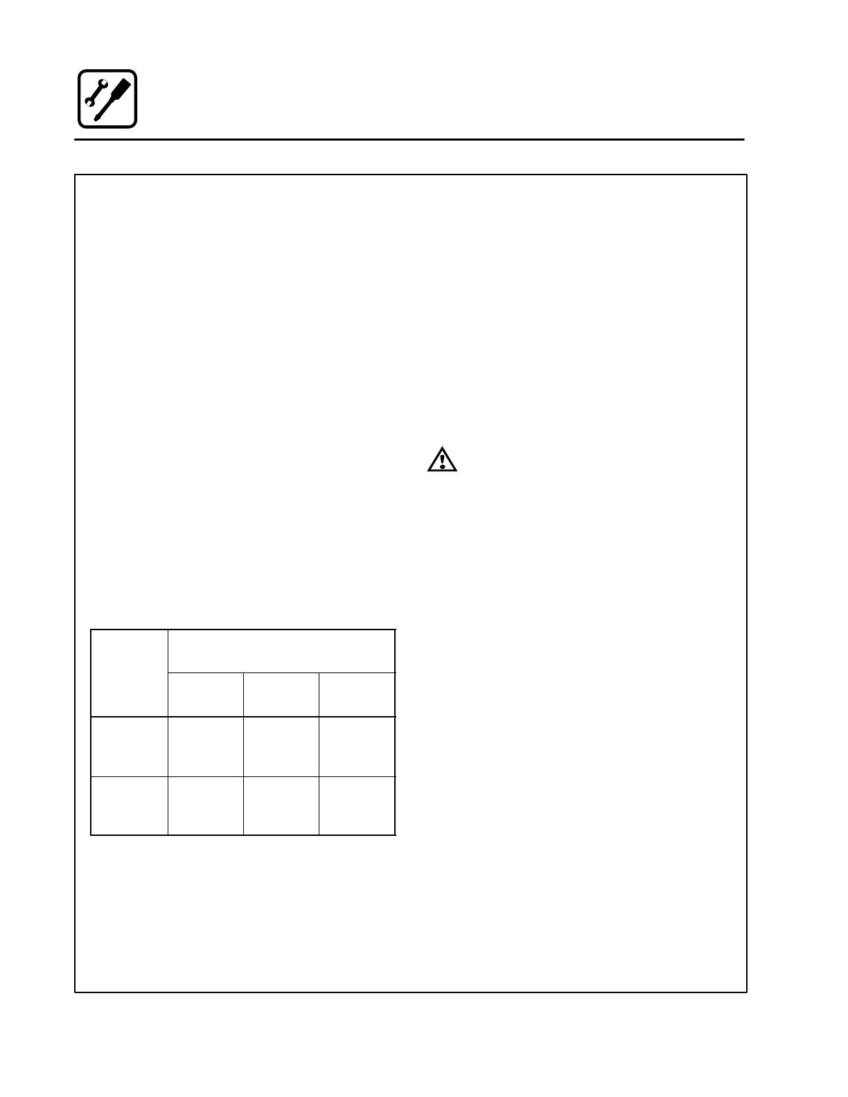
Certain minimum clearances must be maintained
between the oven and any combustible or nonĆ
combustible construction. See the table below.
In addition, the following clearances are recomĆ
mended for servicing.
D Oven body sides - 12" (30cm)
D Oven body back - 12" (30cm)
NOTE: On gas models, routine servicing can usuĆ
ally be accomplished within the limited
movement provided by the gas hose reĆ
straint. If the oven needs to be moved furĆ
ther from the wall, the gas must first be
turned off and disconnected from the oven
before removing the restraint. Reconnect
the restraint after the oven has been reĆ
turned to its normal position.
Left Side Heat Shield
Heat sources should not be near the air vents loĆ
cated on the left hand side of the gas appliance.
Oven
Mdl
MINIMUM REQUIRED
CLEARANCES
Model
Right
Side
Left
Side
Back
BCXĆ14G
BXĆ14G
CNVXĆ14G
6"
(152.4mm)
0"
(0mm)
6"
(152.4mm)
BCXĆ14E
BXĆ14E
CNVXĆ14E
0"
(0mm)
0"
(0mm)
6"
(152.4mm)
VENTILATION
The necessity for a properly designed and inĆ
stalled ventilation system cannot be over emphaĆ
sized. The ventilation system will allow the unit to
function properly while removing unwanted vaĆ
pors and products of combustion from the operatĆ
ing area.
The appliance must be vented with a properly deĆ
signed mechanically driven exhaust hood. The
hood should be sized to completely cover the
equipment plus an overhang of at least 6" (15 cm)
on all sides not adjacent to a wall. The capacity of
the hood should be sized appropriately and proviĆ
sions made for adequate makeup air.
WARNING!!
Failure to properly vent the oven can be
hazardous to the health of the operator;
and will result in operational problems,
unsatisfactory baking, and possible damĆ
age to the equipment. Damage sustained
as a direct result of improper ventilation
will not be covered by the Manufacturer's
warranty.
When installed in the Commonwealth of MassaĆ
chusetts, this appliance must be interlocked with
the hood exhaust system so that the appliance
may be operated only when the hood exhaust sysĆ
tem is running.
U.S. and Canadian Installations
Refer to your local ventilation codes. In the abĆ
sence of local codes, refer to the National ventilaĆ
tion code titled, Standard for the Installation of
Equipment for the Removal of Smoke and Grease
Laden Vapors from Commercial Cooking EquipĆ
ment", NFPAĆ96Ć Latest Edition.
General Export Installations
Installation must conform with Local and National
installation standards. Local installation codes
and/or requirements may vary. If you have any
questions regarding the proper installation and/or
operation of your unit, please contact your local
distributor. If you do not have a local distributor,
please call Blodgett Combi at 0011Ć802Ć860Ć3700.
Installation
9
Leg Attachment
LEG OPTIONS
Legs are available in 4" (101mm), 6" (152mm) āor
25" (ā635mm) ālengths āāor āālow profile casters.
D The 4" (101mm) legs may be used when mountĆ
ing on a counter.
D The 6" (152.4mm) legs are used on the lower
section of a double stacked appliance.
D The ā25" (635mm) legs are used for a single apĆ
pliance located on the floor.
NOTE: For safety reasons, casters must not be
used with the 25" (635mm) legs.
4" (101mm) Leg
6" (152,4mm) Adjustable Leg
Low Profile Casters
25" (635mm) Adjustable Leg
Figure 2
ATTACHMENT
1. Align the threaded stud on one of the front
legs to the bolt āholeā locatedāāā ināā ātheāā bottom ācorĆ
ner of the appliance. Turn the leg clockwise
and tighten to the nearest full turn.
2. Align the leg plate holes with the bolt holes.
Secure with the two 1/2" bolts provided.
3. Repeat the above steps with the other front
leg. If low profile casters are used, install them
with the locking casters in the front of the oven.
The rear casters do not lock. Ensure that the
locks are set on the front casters.
4. Tip the oven up on the newly installed front
legs. If ācastersā are āused, checkā thatā the locksā
areā setā on ātheā front casters. āRepeat āthe above
steps for the rear legs.
5. Level the oven by screwing the adjustable feet
in or out as necessary.
Figure 3
Installation
10
Caster Attachment
1. Place a level on the floor where the casters are
to rest.
2. Place shims under the low side until it is level.
3. Mount the shims between the casters and the
oven as follows:
a.) Align the shims and caster holes with the
bolt holes.
b.) Secure with the 1/2" bolts provided.
NOTE: Install them with the locking casters in
the front of the oven. The rear casters
do not lock. Ensure that the locks are
set on the front casters.
4. Tip the oven up on the newly installed casters.
Add shims as necessary
Exaggerated for clarity
Floor
Figure 4
Installation
11
Stacking
WARNING!!
Stacking should be performed by qualiĆ
fied installation personnel only. The
ovens are heavy. Take care to use proper
tools and techniques when lifting and
stacking units.
1. Attach the legs or casters to the bottom oven.
See page 9 or 10.
2. Place the top oven on the bottom oven. Be
sure all four sides are flush.
3. Remove left side oven panels.
4. Bolt the two ovens together from underneath
into the two threaded nut retainers.
5. GAS APPLIANCES ONLY: Attach the flue
vents and gas manifold as shown.
Steam Generator Flue
(BCXĆ14 only)
Hot Air Flue
Rear View BCXĆ14G
Gas Manifold
Left Side of Ovens
with Side Panels
Removed
Bolt
Threaded
Nut Retainer
Figure 5
Installation
12
Deliming System Connection (BCXĆ14 units only)
1. Push deliming tube onto barbed fitting on
oven back.
Figure 6
2. Cut deliming tube to length using the bottom
of the deliming fluid reservoir in its mounted
position as a guide. Install the jug weight on
the deliming fluid reservoir end of the deliming
tube.
Figure 7
3. Insert the end of the deliming tube with the jug
weight into the deliming solution reservoir.
Figure 8
4. Prime the pump by placing oven in COOL
DOWN mode with the oven on and press and
hold the STEAM ON DEMAND button. Watch
for deliming solution to flow through tube. This
will tell you the pump is working correctly. ReĆ
lease the STEAM ON DEMAND button once
deliming solution has reached the oven back.
NOTE: If needed use supplied hose retainers and
self drilling screws to route the deliming
tube away from hot exhaust ports.
Installation
13
Plumbing Connections
WATER CONNECTION
NOTE: Hot water maximizes steam production but
is not required. Cold water may be supplied
to both inlets if hot water is not available.
Connect the appliance to quality water via a presĆ
sure hose with 3/4" GHT (19mm) couplings. See
Figure 9 for connections. A shut off valve is to be
provided adjacent to the oven.
WARNING!!
Operating the appliance without the water
regulator installed will invalidate your warĆ
ranty.
This product must be installed by a licensed
Plumber or Gas Fitter when installed within the
Commonwealth of Massachusetts.
DRAIN CONNECTION
The drain should be run to an open floor drain
avoiding flexible hose that could sag and allow
trapped water to accumulate. The customer must
supply the piping from the oven to the drain.
Specific water/drain connection for City of Los
Angeles
1. Each drain line from the appliance shall be
routed without dips or sags to terminate above
the flood level rim of an approved indirect waste
receptor.
2. The appliance shall be installed in accordance
with the manufacturer's printed instructions
and the LAPC and LAMC, 1999 editions.
3. A backflow protection device may be required
by local codes. If so, install on the potable water
system directly ahead of the appliance. The
backflow protection device shall be any of the
following: an approved pressure type vacuum
breaker installed at least 12" above the highest
point of use, a double check valve backflow preĆ
venter or a reduced pressure principal backflow
preventer.
Gas
connection
Electrical
connection
Filtered/boiler
connection
Unfiltered/condensate
and spray hose
connection
BCXĆ14G and BXĆ14G BCXĆ14E and BXĆ14E
CNVXĆ14G CNVXĆ14E
Figure 9
Installation
14
Electrical Connections
ELECTRICAL CONNECTION
All Models
NOTE: Electrical connections must be performed
by a qualified installer only.
Before making any electrical connections to these
appliances, check that the power supply is adeĆ
quate for the voltage, amperage, and phase reĆ
quirements stated on the rating name plate
mounted on the appliance.
The circuit breaker that is used to provide power
to this appliance must have a minimum of .076"
(3mm) contact spacing. The circuit breaker must
meet all Local and National installation standards.
All appliances must be installed in accordance
with Local or National Electrical codes.
A wiring schematic is located on the inside of the
removeable side panel.
NOTE: Disconnect the power supply to the apĆ
pliance before servicing.
WARNING!!
Improper installation may invalidate your
warranty.
Electric Models
A strain relief for the power supply cord is provided.
The installer must supply a cord that meets all Local
and National installation standards.
Gas Models
U.S. and Canadian Installations
A power cord (115V or 230V) is supplied with a
plug attached. Plug the power cord into the deĆ
sired receptacle.
WARNING!!
If the supply cord is damaged, it must be
replaced by a special cord or assembly
available from the manufacturer or its serĆ
vice agent.
Installation
15
Gas Connections
GAS PIPING
A properly sized gas supply system is essential for
maximum oven performance. Piping should be
sized to provide a supply of gas sufficient to meet
the maximum demand of all appliances on the line
without loss of pressure at the equipment.
Example:
NOTE: BTU values in the following example are
for natural gas.
You purchase a BCXĆ14G to add to your existing
cook line.
1. Add the BTU rating of your current appliances.
Pitco Fryer 120,000 BTU
6 Burner Range 60,000 BTU
Deck Oven 50,000 BTU
Total 230,000 BTU
2. Add the BTU rating of the new oven to the toĆ
tal.
Previous Total 230,000 BTU
BCXĆ14G 115,000 BTU
New Total 345,000 BTU
3. Measure the distance from the gas meter to
the cook line. This is the pipe length. Let's say
the pipe length is 30' (9 m) and the pipe size
is 1" (2.54 cm).
4. Use the appropriate table to determine the toĆ
tal capacity of your current gas piping.
The total capacity for this example is 375,000
BTU. Since the total required gas pressure,
345,000 BTU is less than 375,000 BTU, the
current gas piping will not have to be inĆ
creased.
NOTE: The BTU capacities given in the tables are
for straight pipe lengths only. Any elbows
or other fittings will decrease pipe capaciĆ
ties. For example: a schedule 40 1Ć1/2" ell
fitting has an equivalent capacity of 4.2"
(10.2 cm) of straight pipe. Contact your loĆ
cal gas supplier if you have any questions.
Maximum Capacity of Iron Pipe in Cubic Feet
of Natural Gas Per Hour
(Pressure drop of 0.5 Inch W.C.)
Pipe
Length
Nominal Size, Inches
L
eng
th
(ft)
3/4" 1" 1Ć1/4" 1Ć1/2" 2"
10 360 680 1400 2100 3950
20 250 465 950 1460 2750
30 200 375 770 1180 2200
40 170 320 660 990 1900
50 151 285 580 900 1680
60 138 260 530 810 1520
70 125 240 490 750 1400
80 118 220 460 690 1300
90 110 205 430 650 1220
100 103 195 400 620 1150
From the National Fuel Gas Code Part 10 Table 10Ć2
Maximum Capacity of Pipe in Thousands of
BTU/hr of Undiluted P.P. Gas at 11" W.C.
(Pressure drop of 0.5 Inch W.C.)
Pipe Length
(ft)
Inside Diameter, Inches
pg
(ft)
3/4" 1" 1Ć1/2"
10 608 1146 3525
20 418 788 2423
30 336 632 1946
40 287 541 1665
50 255 480 1476
60 231 435 1337
70 215 404 1241
80 198 372 1144
90 187 351 1079
100 175 330 1014
From the National Fuel Gas Code Part 10 Table 10Ć15
Installation
16
Gas Connections
PRESSURE REGULATION AND TESTING
The gas pressure to the appliance must be rated
for each appliance while the burners are on. A sufĆ
ficient gas pressure must be present at the inlet to
satisfy these conditions. Refer to the table below
for correct gas pressure.
Each appliance has been adjusted at the factory
to operate with the type of gas specified on the ratĆ
ing plate.
Each oven is supplied with a regulator to maintain
the proper gas pressure. The regulator is essenĆ
tial to the proper operation of the oven and
should not be removed.
DO NOT INSTALL AN ADDITIONAL REGULATOR
WHERE THE UNIT CONNECTS TO THE GAS
SUPPLY UNLESS THE INLET PRESSURE IS
GREATER THAN 14" W.C. (1/2 PSI) (37mbar).
The oven and its individual shutoff valve must be
disconnected from the gas supply piping system
during any pressure testing of that system at test
pressures in excess of 1/2 psig (3.45kPa).
The oven must be isolated from the gas supply
piping system by closing its individual manual
shutoff valve during any pressure testing of the
gas piping system at test pressures equal or less
than 1/2 psig (3.45kPa).
Prior to connecting the appliance, gas lines
should be thoroughly purged of all metal filings,
shavings, pipe dope, and other debris. After conĆ
nection, the appliance must be checked for corĆ
rect gas pressure.
U.S. and Canadian Installations
Installation must conform with local codes, or in
the absence of local codes, with the National Fuel
Gas Code, NFPA54/ANSI Z223.1-Latest Edition,
the Natural Gas Installation Code CAN/CGAĆ
B149.1 or the Propane Installation Code, CAN/
CGAĆB149.2 as applicable.
General Export Installations
Installation must conform with Local and National
installation standards. Local installation codes and/
or requirements may vary. If you have any questions
regarding the proper installation and/or operation of
your appliance, please contact your local distributor.
If you do not have a local distributor, please call
Blodgett Combi at 0011Ć802Ć860Ć3700.
GAS PRESSURE
Gas
T
Inlet
P
Orifice Size at Sea Level Manifold Pressure
Type Pressure
Hot Air Steam Hot Air Steam
BCXĆ14G
Natural 7-14" W.C. .0531" dia .042" dia 3.5" W.C. 3.5" W.C.
Propane 12-14" W.C. .032" dia .026" dia 10.0" W.C. 10.0" W.C.
BXĆ14G and CNVXĆ14G
Natural 7-14" W.C. .0531" dia - 3.5" W.C. -
Propane 12-14" W.C. .032" dia - 10.0" W.C. -
Installation
17
Gas Hose Restraint
If the appliance is mounted on casters, a commerĆ
cial flexible connector with a minimum of 3/4" (1.9
cm) inside diameter must be used along with a
quick connect device.
A restraint must be used to limit the movement of
the appliance so that no strain is placed upon the
flexible connector. The restraint should be fasĆ
tened to the base frame of the oven as close to the
flexible connector as possible. It should be short
enough to prevent any strain on the connector.
With the restraint fully stretched the connector
should be easy to install and quick connect.
The restraint (ie: heavy gauge cable) should be atĆ
tached without damaging the building. DO NOT
use the gas piping or electrical conduit for the atĆ
tachment of the permanent end of the restraint!
Use anchor bolts in concrete or cement block. On
wooden walls, drive hi test wood lag screws into
the studs of the wall.
WARNING!!
If the restraint is disconnected for any reaĆ
son it must be reconnected when the apĆ
pliance is returned to its original position.
U.S. and Canadian installations
The connector must comply with the Standard for
Connectors for Movable Gas Appliances, ANSI
Z21.69 or Connectors For Moveable Gas ApĆ
pliances CAN/CGAĆ6.16 and a quick disconnect
device that complies with the Standard for QuickĆ
Disconnect Devices for Use With Gas Fuel, ANSI
Z21.41 or Quick Disconnect For Use With Gas Fuel
CAN 1Ć6.9. Adequate means must be provided to
limit the movement of the appliance without deĆ
pending on the connection and the quick disconĆ
nect device or its associated piping.
A drip leg must be used at each appliance. Refer
to NFPA54/ANSI Z223.1 Ć Latest Edition (National
Fuel Gas Code) for proper drip leg installation.
General export installations
Installation must conform with Local and National
installation standards. Local installation codes and/
or requirements may vary. If you have any questions
regarding the proper installation and/or operation of
your appliance, please contact your local distributor.
If you do not have a local distributor, please call
Blodgett Combi at 0011Ć802Ć860Ć3700.
Gas Supply Line
Gas Hose
Quick Connect
Installation of Gas Hose and Restraint
(Single Section Shown)
Attachment Plate
(secure with leg mount bolt)
IMPORTANT: Cable restraint should
be fastened as close as possible to the
flexible connector and short enough to
prevent any strain on the flexible conĆ
nector.
At maximum stretch of shortened reĆ
straint, the flexible connector should
be easy to install and quick to connect.
Restraint
Figure 10
Installation
18
Adjustments
Before applying power to the appliance for the first
time, check for the following conditions:
j All āelectricalā safety provisions have been adĆ
hered to and the electrical connections are
correct.
j Water is connected, turned on and all of the
connections are water tight.
j The āpanā holders are āinserted āinto the oven
cavity.
j Cardboard has been removed from oven cavĆ
ity.
j Gas has been turned on, if gas unit.
DOOR ADJUSTMENT
The door catch may be adjusted in and out using
the following procedure:
1. Flip the rubber boot on the catch towards you.
2. Loosen the locknut to make adjustment.
3. Rotate the catch clockwise or counter clockĆ
wise to get proper adjustment.
4. Retighten locknut, assuring the catch is vertiĆ
cal.
5. Flip the rubber boot back into position.
The hinges can also be adjusted as follows:
1. Loosen the two 1/4Ć20 bolts on the top of the
hinge plate and the two bolts on the bottom
hinge plate.
2. Apply pressure to the door on the corners to
get the proper seal. While pushing, tighten the
bolts in place.
Figure 11
  • Page 1 1
  • Page 2 2
  • Page 3 3
  • Page 4 4
  • Page 5 5
  • Page 6 6
  • Page 7 7
  • Page 8 8
  • Page 9 9
  • Page 10 10
  • Page 11 11
  • Page 12 12
  • Page 13 13
  • Page 14 14
  • Page 15 15
  • Page 16 16
  • Page 17 17
  • Page 18 18
  • Page 19 19
  • Page 20 20
  • Page 21 21
  • Page 22 22
  • Page 23 23
  • Page 24 24
  • Page 25 25
  • Page 26 26
  • Page 27 27
  • Page 28 28
  • Page 29 29
  • Page 30 30
  • Page 31 31
  • Page 32 32
  • Page 33 33
  • Page 34 34
  • Page 35 35
  • Page 36 36
  • Page 37 37
  • Page 38 38
  • Page 39 39
  • Page 40 40
  • Page 41 41
  • Page 42 42
  • Page 43 43
  • Page 44 44
  • Page 45 45
  • Page 46 46
  • Page 47 47
  • Page 48 48
  • Page 49 49
  • Page 50 50
  • Page 51 51
  • Page 52 52
  • Page 53 53
  • Page 54 54
  • Page 55 55
  • Page 56 56
  • Page 57 57
  • Page 58 58
  • Page 59 59
  • Page 60 60
  • Page 61 61
  • Page 62 62
  • Page 63 63
  • Page 64 64
  • Page 65 65
  • Page 66 66
  • Page 67 67
  • Page 68 68
  • Page 69 69
  • Page 70 70
  • Page 71 71
  • Page 72 72
  • Page 73 73
  • Page 74 74
  • Page 75 75

Blodgett BX-14G User manual

Category
Cookers
Type
User manual
This manual is also suitable for

Ask a question and I''ll find the answer in the document

Finding information in a document is now easier with AI