
Brandstoffilters/waterafscheiders
Fuel Filters/Water Separators
Treibstofffilter und
Wasserabscheider
Filtres à carburant/séparateurs d’eau
Filtras de combustible/Separadores de
agua
Filtri carburante/separatore d’acqua
Copyright © 2010 Vetus n.v. Schiedam Holland
3
6
9
12
15
18
Bedieningshandleiding en
installatieinstructies
Operation manual and
installation instructions
Bedienungshandbuch und
Einbauanleitung
Manuel d’utilisation et
instructions d’installation
Manual de manejo y
instrucciones de instalación
Manuale per l’uso e
istruzioni per l’installazione
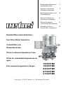
75100VTME
79100VTME
83100VTME
87100VTME
91100VTME

2 040306.01
Fuel Filters/Water Separators
Dit produkt voldoet aan de norm: ISO 10088
This product complies to the standard: ISO 10088
Dieses Produkt entspricht der ISO Norm 10088
Ce produit est conforme à la norme: ISO 10088
Este producto cumple la norma: ISO 10088
Questo prodotto è conforme alla norma: ISO 10088
75100VTME
79100VTME
83100VTME
87100VTME
91100VTME
Page is loading ...
Page is loading ...
Page is loading ...

6 040306.01
Fuel Filters/Water Separators
General
Vetus fuel filters/water separators
75100VTME, 79100VTME, 83100VTME,
87100VTME and 91100VTME have a
unique and patented filter with three filtra-
tion steps.
1) Firstly, 80% of the solid dirt particles and
the water, which is heavier than fuel, are
collected in the transparent collection
basin.
2) After this, the fuel flows upwards. Water
and solid dirt particles are separated
by means of the coalescence effect (to
coalesce is for microscopically small
fluid droplets to stick together as a larger
drop) and also collected in the transpar-
ent collection basin.
3) Finally, the fuel flows further upwards
through the filter mechanism, the prima-
ry function of which is to hold back the
smallest solid dirt particles and water:
this ensures a high degree of filtration
and a long lifetime for the fine filter on the
engine.
These filters are suitable for diesel fuel
only.
Installation
Note:
Bear in mind the regulations that your
local authorities have imposed regarding
the specification and installation of fuel
tanks and pipework.
Warning
The filter is under pressure (with a
pressurised non-inflammable gas).
Prior to fitting the filter, remove the caps
on the connections to the fuel supply
line and open the valves to depressurise
the filter.
If the valves are opened (with a full fuel
tank) once the filter has already been
fitted, fuel will no longer be drawn into
the filter!
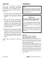
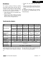
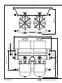
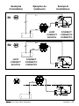
Layout
For vessels under construction:
(See illustrations A1 and A2)
Mount the suction pipe at the bottom of the
tank; the bottom of the tank is thus kept
clean at all times and the build-up of water
and bacteria is prevented.
The fuel return line must be led into the
top of the tank, and must feed down to the
bottom of the tank on the opposite side
from the suction pipe. This prevents foam
forming in the fuel tank: the constant flow
of fuel ensures that the build-up of dirt, and
thus cleaning expenses for the tanks, are
not incurred.

040306.01 7
Fuel Filters/Water Separators
ENGLISH
For existing vessels:
(See illustrations B1 and B2):
Interpose the fuel filter/water separator in
the fuel supply pipe, between the fuel tank
and the fuel feed pump.
To avoid the fuel tank emptying out should a
leak arise somewhere in the fuel line to the
engine, a cutoff should be fitted near the
tank’s suction connection.
All fine filters installed before or after the fuel
feed pump must remain in position.
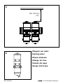
Mount the filter housing against a vertical
bulkhead.
Ensure there is sufficient space below the
filter to allow separated water to be drained
off.
Ensure sufficient space above the unit
for replacement of the filter element. See
Drawing 3.
Pay attention to the flow direction. This is
clearly marked.
Bleed the fuel system, if it is not an auto-
matically de-aerating one. See ‘Bleeding’.
Start the engine and check the fuel system
for leakages.
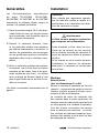
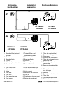
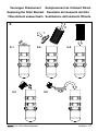
Maintenance
Draining water from the water sepa-
rator:
Drain monthly the water collected in the
water separator. If a large amount of water
is seen to collect in the transparent collec-
tion basin, you will have to drain it off more
frequently. See illustration 4.
Replacing the filter element:
Replace the filter element at least once a
year or every 200 engine hours, whichever
occurs the sooner.
If the vacuum gauge indicates a pressure
within the orange zone (-0.2 to -0.38 kg/
cm
2
), you must replace the filter element as
soon as possible.
Proceed as follows:
See illustration 5.
• Acquire a replacement filter element:
Vetus article code 2020VTR (stand-
ard model, with a fineness of 30µ) or
2020VTB (with a fineness of 10µ).
• Open any taps that are still closed.
Close the taps on the filter that is to be
replaced. It is not necessary to stop the
engine.
• Loosen the T-handle and open the
cover.
• Slidetheoldelementveryslowlyoutof
the housing.
• Put the new element very slowly into
position.
• Fillthefilterwithsufficientcleanfuel;by
doing this, you will not have to de-aerate
the system.
• Apply a thin layer of engine oil to the
O-ring and fit the cover to the filter hous-
ing.
• TightentheT-handlehand-tight.
Use NO tools to tighten the T-handle.
Bleeding
Most engines nowadays are self-bleeding.
If this is not the case, you will have to bleed
the system yourself after having drained
off the water or having replaced the filter
element.
• Fillthefilterwithsufficientcleanfuel.
• Apply a thin layer of engine oil to the
O-ring and fit the cover to the filter hous-

8 040306.01
Fuel Filters/Water Separators
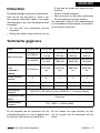
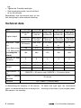
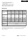
Technical data
Type 75100VTME 79100VTME 83100VTME 87100VTME 91100VTME
Engine output
up to 500
HP
from 500 to
1100 HP
from 1100
to 2300 HP
from 2300
to 3600 HP
from 3600
to 5000 HP
to 368 kW
from 368 to
810 kW
from 810 to
1692 kW
from 1692
to 2648 kW
from 2648
to 3678 kW
Maximum capa-
city
720 litres/hr
1440 litres/
hr
2160 litres/
hr
2880 litres/
hr
3600 litres/
hr
Imp. Gallon/hour 158 316 474 632 790
US Gallon/hour
(consumption +
return)
190 380 570 760 950
Number of filter
elements
2 3 4 5 6
Connections R 3/4 R 1 R 1 1/2 R 1 1/2 R 1 1/2
Weight
12,5 kg 20 kg 27,6 kg 35 kg 41 kg
27.5 lbs 44 lbs 60.8 lbs 77.1 lbs 90.4 lbs
Replacement fil-
ter
2020VTR = 30 micron red), 2020VTB = 10 micron (blue)
Filter grade
standard
30 micron
Certified CE + ABYC + SOLAS (IMO)
ing.
• TightentheT-handlehand-tight.
• Starttheengineandletitrunathalfthrot-
tle for 30 seconds.
Alternatively: Use the manual lever on the
fuel feed pump to allow manual bleeding.
In determining the capacity of the various
types, it is assumed that there is always one
filter spare or on stand-by.
To select the right type, we recommend
working on the basis of your engine power.
Page is loading ...
Page is loading ...
Page is loading ...
Page is loading ...
Page is loading ...
Page is loading ...
Page is loading ...
Page is loading ...
Page is loading ...
Page is loading ...
Page is loading ...
Page is loading ...
Page is loading ...
Page is loading ...
Page is loading ...
Page is loading ...

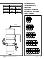
040306.01 25
Fuel Filters/Water Separators
Exemples
d’installation
Ejemplos de
instalación
Esempi di
installazione
4
5
1
3
2
6
4
5
1
2
3
6
4
5
1
3
2
B2
B1
JUIST
CORRECT
RICHTIG
CORRECT
CORRECTO
CORRETTO
JUIST
CORRECT
RICHTIG
CORRECT
CORRECTO
CORRETTO

26 040306.01
Fuel Filters/Water Separators
4
Aftappen van water
Draining water
Wasser ablassen
Vidange de l’eau
Vaciado del agua
Spurgo dell’acqua
Min. 300 mm
(12”)
3
Page is loading ...

Printed in the Netherlands
040306.01 2010-07
FOKKERSTRAAT 571 - 3125 BD SCHIEDAM - HOLLAND - TEL.: +31 10 4377700
TELEFAX: +31 10 4372673 - 4621286 - E-MAIL: [email protected] - INTERNET: http://www.vetus.com
vetus n.v.
-
 1
1
-
 2
2
-
 3
3
-
 4
4
-
 5
5
-
 6
6
-
 7
7
-
 8
8
-
 9
9
-
 10
10
-
 11
11
-
 12
12
-
 13
13
-
 14
14
-
 15
15
-
 16
16
-
 17
17
-
 18
18
-
 19
19
-
 20
20
-
 21
21
-
 22
22
-
 23
23
-
 24
24
-
 25
25
-
 26
26
-
 27
27
-
 28
28


Vetus Centrifugal filters type ..VTE Installation guide
- Type
- Installation guide
- This manual is also suitable for
Ask a question and I''ll find the answer in the document
Finding information in a document is now easier with AI
in other languages
- italiano: Vetus Centrifugal filters type ..VTE Guida d'installazione
- français: Vetus Centrifugal filters type ..VTE Guide d'installation
- español: Vetus Centrifugal filters type ..VTE Guía de instalación
- Deutsch: Vetus Centrifugal filters type ..VTE Installationsanleitung
- Nederlands: Vetus Centrifugal filters type ..VTE Installatie gids
Related papers
-
Vetus 320VTNEB Installation guide
-
-
-
-
-
-
-
-
-
Other documents
-
protech nitro fun 12 User manual
-
-
-
-
Hitachi CG51EASL Owner's manual
-
McCulloch GB 320 Owner's manual
-
-
Mase IS 06.5-07.6 Usage Manual
-
Scheppach 5911104903 User manual
-
Lavorwash Independent 2300 Owner's manual