Please read the Important Safety Information and specications
sections at the front of this guide, and the requirements detailed
in this section before installing the shower.
Plumbing
1. The plumbing installation must comply with all national or local
water regulations and all relevant building regulations, or any
particular regulation or practice specied by the local water
supply company.
2. Do not install the product in a position in which service access
is limited.
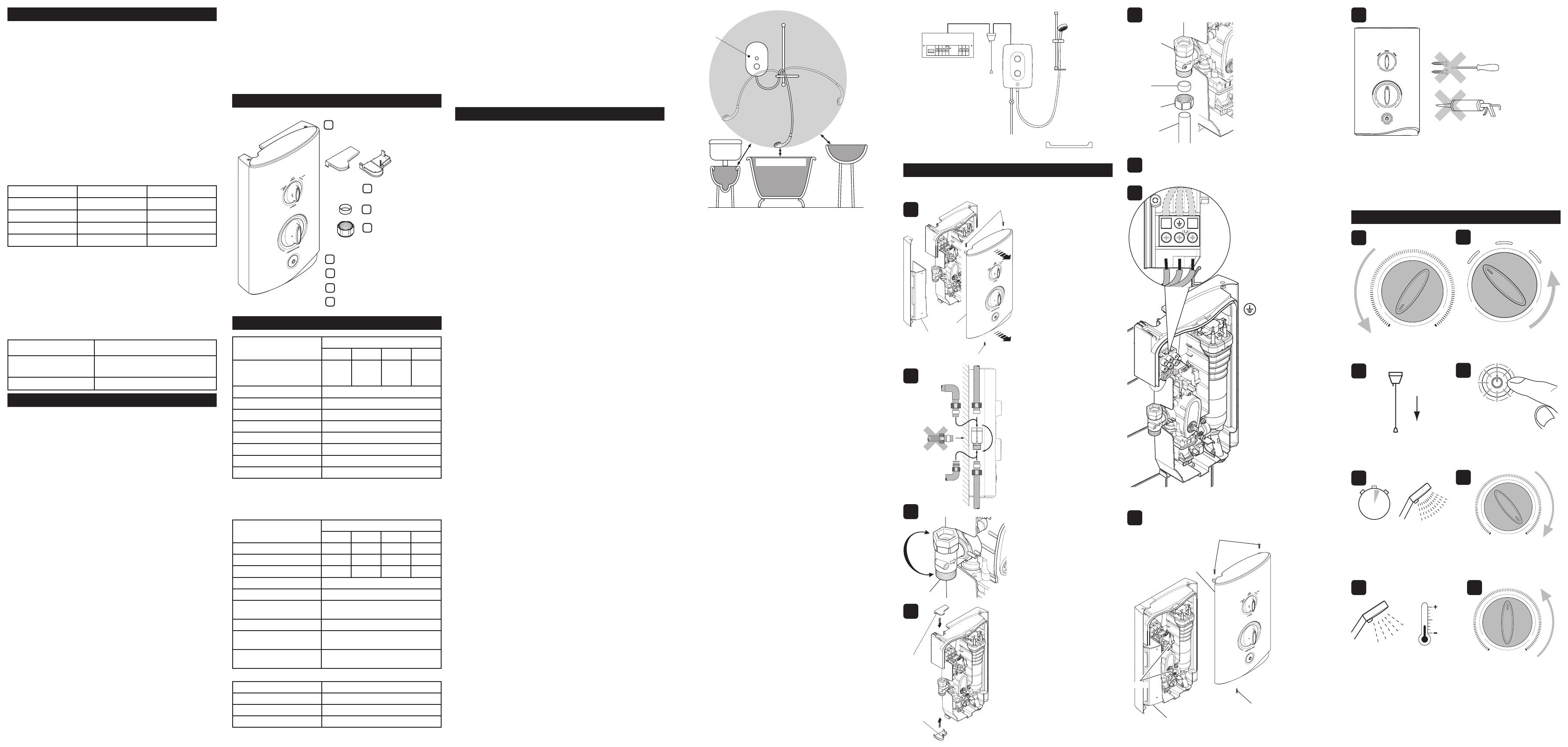
3. Decide on a suitable position for the shower (minimum distance
of 200 mm from the ceiling to allow for cover t and removal).
4. The position of the shower and shower ttings must provide a
minimum gap of 25 mm between the showerhead and the spill
over level of any bath, shower tray or basin and a minimum
gap of 30 mm between the showerhead and the spill over level
of any toilet, bidet or other appliance with a Fluid Category 5
backow risk (see diagram on next page).
5. The shower is suitable for installation within the shower area
and is tted with a pressure relief valve. It must be positioned
over a water catchment area with the controls at a convenient
height for the user.
6. The shower must be tted to a waterproof at and even wall
surface.
7. DO NOT t the shower to the wall and tile up to the case.
8. DO NOT seal the gap between the shower and the wall surface.
9. The showerhead should be positioned so that it discharges down
the centre line of the bath or across the opening of a shower
cubicle.
10. The showerhead must be directed away from the shower unit,
during normal use the showerhead must not spray directly on
to the shower unit.
11. DO NOT apply excessive force to plumbing connections;
always provide mechanical support when making plumbing
connections. Any soldered joints should be made before
connecting the shower.
12. This shower is not designed to be plumbed directly from the
rear. For rear-entry supply, add an elbow to the supply pipe and
connect as a rising or a falling supply.
13. If pipework and/or electrical cables enter the shower from the
rear through a hole in the wall provision must be made to prevent
water ingress back into the wall structure.
14. Only use the inlet connector supplied with the shower. DO NOT
use any other type of tting.
15. A full bore/non restrictive servicing valve must be tted in a
readily accessible position adjacent to the shower to facilitate
maintenance of the shower. DO NOT use a valve with a loose
washer plate (jumper) as this can lead to a build up of static
pressure.
16. A water treatment device should be installed where the water
hardness may exceed 200 ppm. Malfunctions caused by
excessive limescale formation are not covered by this shower’s
guarantee (see back page for details).
17. The installation must not cause the hose to be sharply kinked
during normal use.
18. DO NOT perform the electrical installation until the plumbing
has been completed and checked for leaks.
19. Wall xings are not supplied. For solid wall structures a red
rawl plug and a no. 8 x 1½” countersunk brass or stainless steel
screw should be used. For other wall structures such as panels
alternative xings may be required. A minimum of 3 xing screws
should be used.
INSTALLATION REQUIREMENTS
WARNING - TO REDUCE THE RISK OF FIRE, ELECTRIC
SHOCK OR INJURY.
Zone of
Backow Risk
30 mm
Minimum
Toilet or Bidet
FC5
Hand Basin
FC3
Bath or Shower
Tray FC3
Electric
Shower
25 mm
Minimum
25 mm Minimum
Hose Retaining Ring tted and shower ttings xed at a suitable
height preventing dirty water backow.
Note! There will be occasions when the hose retaining ring will
not provide a suitable solution for Fluid Category 3 installations, in
these instances an outlet double checkvalve must be tted, this will
increase the required supply pressure typically by 10kPa (0.1 bar).
Double checkvalves tted in the inlet supply to the appliance cause
a pressure build up, which affect the maximum static inlet pressure
for the appliance and must not be tted. For Fluid category 5 double
checkvalves are not suitable.
Plumbing and Electrical Schematic
WARNING - TO REDUCE THE RISK OF FIRE, ELECTRIC
SHOCK OR INJURY.
Warning! Isolate the electrical and water supplies before installing
the shower.
Cover
Screw
Screws
Service
Tunnel
Remove the three screws that
hold the cover on and remove
the cover.
Remove the service tunnel.
Caution! Do not drill into
cables or pipes in the wall.
INSTALLATION
Rotate the inlet connector
to suit the direction of the
incoming water supply.
Secure the shower to the wall
with appropriate wall xings.
Thoroughly ush the supply
pipe.
Determine the direction and
route of the incoming water
supply: falling (entering the
shower from the top), or rising
(entering the shower from the
bottom).
Note! - DO NOT use an
incoming supply entering the
shower directly from the back.
Add an elbow to the supply
pipe and connect it as a rising
or falling supply.
Case
Insert
Electrical
1. The electrical installation must comply with BS 7671 (commonly
referred to as the IEE Wiring Regulations) and all relevant
building regulations, or any particular regulation or practice
specied by the local electricity supply company.
2. Ensure that all circuit protection devices, switches and cabling is
adequate for the rated current of the shower and that the rating
of the electricity supply company fuse and the consumer unit
are adequate for the additional demand.
3. The shower must be earthed. Ensure any supplementary
bonding complies with the relevant regulations.
4. This shower is intended to be permanently connected to the
xed electrical wiring of the mains system. A separate supply
must be provided from the consumer unit to the shower.
5. DO NOT supply any other electrical equipment including
extractor fans or pumps via this product.
6. This shower must be provided with means for local disconnection
that is incorporated into the xed wiring in accordance with the
relevant local wiring regulations. This must be a double pole
switch, which has at least 3 mm contact separation in each pole.
The switch can be a ceiling mounted pull-cord type within the
shower room or a wall mounted switch tted in the applicable
zone area.
7. A 30mA Residual Current Device (RCD) is recommended to
be incorporated into the electrical supply to this shower in
accordance with wiring regulations.
8. DO NOT apply excessive force to the terminal block.
9. All electrical connections should be checked for tightness to
prevent overheating before switching on the electrical supply.
10. DO NOT switch on the electrical supply until the plumbing has
been completed and checked for leaks.
1
2
3
4
5
6
7
8
Install the shower fittings
(Refer to the Shower Fittings
Installation and User Guide
packed with the product).
INTRODUCTION
IMPORTANT SAFETY INFORMATION
WARNING - This shower can deliver scalding temperatures if
not operated, installed or maintained in accordance with the
instructions, warnings and cautions contained in this guide and
on or inside the appliance.
TO REDUCE THE RISK OF FIRE, ELECTRIC SHOCK OR INJURY:
1. Installation of this shower must be carried out in accordance
with these instructions by qualied, competent personnel.
2. Isolate the electrical and water supplies before commencing
installation. The electricity must be isolated at the consumer unit
and the appropriate circuit fuse removed, if applicable. Mains
connections are exposed when the cover is removed.
3. DO NOT install the shower in areas with high humidity and
temperature (i.e. steam rooms and saunas).
4. DO NOT install the shower where it may be exposed to freezing
conditions. Ensure that any pipework that could become frozen
is properly insulated.
5. DO NOT switch the shower on if there is a possibility that the
water in the shower is frozen.
6. DO NOT switch the shower on if water starts leaking from
the shower case. Isolate the electrical supply to the shower
immediately.
7. DO NOT connect the outlet of the shower to any tap, control
valve, trigger handset or showerhead other than those specied
for use with this shower. Only Kohler Mira recommended
accessories should be used.
8. The water supplies to this product must be isolated if the product
is not to be used for a long period of time. If the product or
pipework is at risk of freezing during this period they should
also be drained of water.
9. DO NOT perform any unspecied modications to the shower
or its accessories. When servicing only use genuine Kohler Mira
replacement parts.
Patents and Design Registration
Design Registration: 001259 287-0002, 001259 287-0005
Patents: GB 2 341 667, 2 427 460
Ireland 82835
Patent Application:
Ireland: 2006/0462
Guarantee
This product has been designed for domestic use only, Mira Showers
guarantee this product against any defect in materials or workmanship
for a period of two years from the date of purchase (shower ttings
for one year).
For terms and conditions, refer to the back cover of this guide.
Product Model Number Colour
Mira Sport 7.5 kW J03A White/Chrome
Mira Sport 9.0 kW J03B White/Chrome
Mira Sport 9.8 kW J03C White/Chrome
Mira Sport 10.8 kW J03D White/Chrome
Thank you for purchasing a quality Mira Sport Electric Shower. To
enjoy the full potential of your new shower, please take time to read
this guide thoroughly, and keep it handy for future reference.
Products manufactured by Kohler Mira Ltd are designed to be safe
provided, that they are installed used and maintained in good working
order, in accordance with our instructions and recommendations.
Follow all warnings, cautions and instructions contained in this guide,
and on or inside the shower.
Mira Sport electric showers have separate controls for power selection
and for temperature/ow adjustment. A unique ow regulator stabilises
any temperature changes caused by water pressure uctuations,
which can result from taps being turned on or off or toilets being
ushed.
When this shower has reached the end of its serviceable life, it should
be disposed of in a safe manner, in accordance with current local
authority recycling, or waste disposal policy.
Mira Sport models covered by this guide:
European Conformity Information
The Mira Sport range of showers complies with the following
European directives:
2006/95/EC Low Voltage Directive, 2004/108/EC EMC Directive.
The Mira Sport range of showers are high power appliances and are
subject to conditional connection. If the main electrical supply fuse is
rated less than 80 Amps, the local electricity supply company must be
contacted to conrm if the electrical supply is adequate.
The Mira Sport range of showers complies with the requirements of
the UK’s water regulations.
10. If the shower is dismantled during installation or servicing then
upon completion the product must be inspected to ensure all
electrical connections are tight and that there are no leaks.
11. Read all installation instructions before installing this shower.
12. Upon completion of the installation, make sure that the user is
familiar with the operation of the shower, and leave this guide
and the user guide with the owner.
Documentation
1 x Electric Shower
2 x Case Inserts
1 x Installation Guide
1 x User Guide
1 x Guarantee Brochure
PACK CONTENTS
SPECIFICATION
Plumbing Variant
7.5 9.0 9.8 10.8
Minimum Dynamic Pressure 70 kPa
(0.7
bar)
70 kPa
(0.7
bar)
70 kPa
(0.7
bar)
100 kPa
(1.0
bar)
Maximum Dynamic Pressure* 500 kPa (5.0 bar)
Maximum Static Pressure* 1000 kPa (10 bar)
Minimum Static Pressure 20 kPa (0.2 bar)
Maximum Inlet Temperature 30°C
Minimum Inlet Temperature 2°C
Inlet Connection 15 mm Compression/1/2” BSP Male
Maximum Water Hardness 200 ppm CaCO
3
Outlet Connection 1/2” BSP Male
Electrical Variant
7.5 9.0 9.8 10.8
Nominal Power at 240 V ac 7.5 kW 9.0 kW 9.8 kW 10.8 kW
Nominal Power at 230 V ac 6.9 kW 8.3 kW 9.0 kW 9.9 kW
Recommended MCB Rating 32 A 40A 45A 45A
Maximum Supply Cable Size 16 mm²
Recommended RCD Rating 30 mA tripping current
Recommended Isolator
Switch
45 A double-pole with 3 mm contact
separation
Appliance Sealing Rating IP X4 - Suitable for installation in Zone 1
Maximum Ambient
Temperature
30°C
Minimum Ambient
Temperature
2°C
Dimensions
Height 358 mm
Width 215 mm
Depth 90 mm
1 x Compression Nut
1 x Olive
1 x Installation Template
*A drop tight pressure reducing valve should be installed where
dynamic or static pressure exceeds the figure stated in the
Specications.
Using the installation template
supplied, mark the positions of
the three xing holes.
Inlet Connector
Upper and lower case inserts
are supplied and should be
tted.
Note! - Trim the inserts if
necessary to fit incoming
electrical or water supplies
before tting.
Note! Ensure that there are
sufcient lengths of supply pipe
and electrical cable to reach
the connection points.
Remove the installation
template and drill three holes
to suit the xing screws and
wall plugs.
L
N
Loosen the screws in the
terminal block and insert the
wires.
Inlet Connector
Olive
Compression Nut
Inlet Supply Pipe
Connect the inlet supply pipe
to the inlet connector using
the compression nut and olive
(supplied).
Always provide mechanical
support when making plumbing
connections.
Upon completion of the
installation ensure connections
and back case are not under
any stress due to misaligned
pipework or electrical cables.
Strip back sufcient outer cable
insulation to enable routing to
terminal block.
Fit an earth sleeve to the earth
wire.
Tighten the screws in the
terminal block, ensure the
wires are secure and tight.
N (Neutral) = Blue Wire
L (Live) = Brown Wire
(Protective Earth) =
Green /Yellow Sleeved Wire
Turn on the water supply and
check for leaks.
Tighten the three cover
screws.
Screws
Cover
Spindles
Service Tunnel
Screw
LOWHIGH
ECO
POWER
TEMPERATURE
Do not use alternative screws
to secure the cover. This can
cause internal damage to the
appliance.
Do not seal around the back
of appliance.
This completes the installation,
follow the guidelines in section
'COMMISSIONING' to prepare
the shower for use.
Ensure the earth bonding
complies with relevant
regulations.
Replace the service
tunnel.
Ensure the control
dials are aligned
with the spindles
and replace the
cover.
9
Turn temperature control to the
cold position.
Turn power control to low.
Push START/STOP button.
Light in the button illuminates.
Slowly turn the temperature
control to the hot position.
Turn temperature control
back to the midway position.
Flow is reduced and temperature
remains cool.
TEMPERATURE
TEMPERATURE
LOW HIGH
ECO
POWER
TEMPERATURE
COLD
HOT
Switch on the electrical supply.
Water ows freely within a few
seconds, temperature remains
cool.
1
3
2
4
6
5
7
0 - 15 secs
COMMISSIONING
8
Case
Insert