MTD 24AB561D352 Owner's manual
- Category
- Log splitters
- Type
- Owner's manual
This manual is also suitable for

YARD
OPERATOR'S MANUAL
Log Splitter
Vertical Shaft
Assembled
Model Series
500, 501,510, 511
530, 550, 560, and 561
MTD
Jililililili_,,_i_,!_:,,_!_!_:i::,i!!:/,i,_i,_!_,,,,,_,,',,!Siiii,:i,_,_,!:,:_,,,_i,_i!i!i!i!i!i!i__!iiiilil__!i!i!i!!_:i!i!i!i!_I,
IMPORTANT: READ SAFETY RULES AND INSTRUCTIONS CAREFULLY
Warning: This unit is equipped with an internal combustion engine and should not be used on or near any unimproved forest-
covered, brush-covered or grass-covered land unless the engine's exhaust system is equipped with a spark arrester meeting
applicable local or state laws (if any). If a spark arrester is used, it should be maintained in effective working order by the operator.
In the State of California the above is required by law (Section 4442 of the California Public Resources Code). Other states may have
similar laws. Federal laws apply on federal lands. A spark arrester for the muffler is available through your nearest engine authorized
service dealer or contact the service department, P.O. Box 368022 Cleveland, Ohio 44136-9722.
MTD PRODUCTS INC. P.O. BOX 368022 CLEVELAND, OHIO 44136-9722
PRINTED IN U.S.A. FORM NO. 770-10055B
ECO No. 1481 (5/00)

TABLEOFCONTENTS
Content Page
Important Safe Operation Practices ................................................................... 3
Assembling Your Log Splitter ............................................................................. 5
Know Your Log Splitter ...................................................................................... 7
Operating Your Log Splitter ................................................................................ 8
Adjusting Your Log Splitter ................................................................................. 10
Maintaining Your Log Splitter ............................................................................. 10
Conditions That Will Void Warranty ................................................................... 12
Troubleshooting ................................................................................................. 12
Parts List ............................................................................................................ 14
FINDINGMODELNUMBER
This Operator's Manual is an important part of your new log splitter. It will help you assemble, prepare and
maintain the unit for best performance. Please read and understand what it says.
Before you start assembling your new equipment, please locate the model plate on the
equipment and copy the informationfrom itin the space provided below. The information on
the model plate is very important if you need help from our Customer Support Department or
an authorized dealer.
You can locate the model number by standing behind the unit and looking down at the hydraulic tank.
A sample model plate is explained below. For future reference, please copy the model number and
the serial number of the equipment in the space below.
(Model Number) (Sedal Number)
MTD PRODUCTS INC
CLEVELAND, OHIO 44136
Copy the model number here:
Copy the serial number here:
CALLINGCUSTOMERSUPPORT
If you have difficulty assembling this product or have any questions regarding the controls, operation or
maintenance of this unit, please call the Customer Support Department.
Call 1- (330) 220-4MTD (4683) or 1- (800)-800-7310 to reach a Customer Support
representative. Please have your unit's model number and serial number ready when you
call. See previous section to locate this information. You will be asked to enter the serial
number in order to process your call.

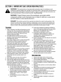
SECTION1: IMPORTANTSAFEOPERATIONPRACTICES
WARNING: This symbol points out important safety instructions which, if not followed, could
endanger the personal safety and/or property of yourself and others. Read and follow all instructions in
this manual before attempting to operate this machine. Failure to comply with these instructions may
result in personal injury. When you see this symbol - heed its warning.
WARNING: Engine Exhaust, some of its constituents, and certain vehicle
components contain or emit chemicals known to State of California to cause cancer
and birth defects or other reproductive harm.
DANGER: This machine was built to be operated according to the rules for safe operation in this
manual. As with any type of power equipment, carelessness or error on the part of the operator can
result in serious injury. This machine is capable of amputating hands and feet and throwing objects.
Failure to observe the following safety instructions could result in serious injury or death.
TRAINING
1. Read, understand, and follow all instructions on the
machine and in the manual(s) before attempting to
assemble and operate. Keep this manual in a safe
place for future and regular reference and for
ordering replacement parts.
2. Befamiliar with all controls and their proper
operation. Know how to stop the machine and
disengage them quickly.
3. Never allow children under 14 years old to operate
this machine. Children 14 years old and over
should read and understand the operation
instructions and safety rules in this manual and
should be trained and supervised by a parent.
4. Never allow adults to operate this machine without
proper instruction.
5. Many accidents occur when more than one person
operates the machine. If a helper is assisting in
loading logs, never activate the control until the
helper is a minimum of 10 feet from the machine.
6. Keep bystanders, helpers, pets, and children at
least 20 feet from the machine while it is in
operation.
7. Never allow anyone to ride on this machine.
8. Never transport cargo on this machine.
9. Hydraulic log splitters develop high fluid pressures
during operation. Fluid escaping through a pin hole
opening can penetrate your skin and cause blood
poisoning, gangrene, or death. Give attention to the
following instructions at all times:
a. Do not check for leaks with your hand.
b. Do not operate machine with frayed, kinked,
cracked, or damaged hoses, fitting, or tubing.
c. Stop the engine and relieve hydraulic system
pressure before changing or adjusting
fittings, hoses, tubing, or other system
components.
d. Do not adjust the pressure settings of the
pump or valve.
10. Leaks can be detected by passing cardboard or
wood, while wearing protective gloves and safety
glasses, over the suspected area. Look for
discoloration of cardboard or wood.
11. If injured by escaping fluid, see a doctor
immediately. Serious infection or reaction can
develop if proper medical treatment is not
administered immediately.
12. Keep the operator zone and adjacent area clear for
safe, secure footing.
13. If your machine is equipped with an internal
combustion engine and it is intended for use near
any unimproved forest, brush, or grass covered
land, the engine exhaust should be equipped with a
spark arrester. Make sure you comply with
applicable local, state, and federal codes. Take
appropriate firefighting equipment with you.
14. This machine should be used for splitting wood
only, do not use itfor any other purpose.
15. Follow the instructions in the manual(s) provided
with any attachment(s) for this machine.
PREPARATION
1. Always wear safety shoes or heavy boots.
2. Always wear safety glasses or safety goggles
during operating this machine.
3. Never wear jewelry or loose clothing that might
become entangled inmoving or rotating parts of the
machine.
4. Make sure this machine is on level surface before
operating.
5. Always block the machine as required to prevent
unintended movement, and lock in either the
horizontal or vertical position.
6. Always operate this machine from the operator
zone(s) specified in the manual.
7. Logs should be cut with square ends prior to
splitting.
8. Use your log splitter in daylight or under good
artificial light.

g.
To avoid personal injury or property damage use
extreme care in handling gasoline. Gasoline is
extremely flammable and the vapors are explosive.
Serious personal injury can occur when gasoline is
spilled on yourself or your clothes which can ignite.
Wash your skin and change immediately.
a. Use only an approved gasoline container.
b. Extinguish all cigarettes, cigars, pipes, and
other sources of ignition.
c. Neverfuel machine indoors.
d. Never remove gas cap or add fuel while the
engine is hot or running.
e. Allow engine to cool at least two minutes
before refueling.
f. Never overfill the fuel tank. Fill tank to no
more than 1/2 inch below bottom of filler neck
to provide space for fuel expansion.
g. Replace gasoline cap and tighten securely.
h. If gasoline is spilled, wipe it off the engine
and equipment, move machine to another
area. Wait 5 minutes before starting the
engine.
i. Never store the machine or fuel container
inside where there is an open flame, spark or
pilot light as on a water heater, space heater,
furnace, clothes dryer or other gas
appliances.
j. Allow machine to cool at least 5 minutes
before storing.
OPERATION
1. Before staring this machine, review the "Safety
Instructions". Failure to follow these rules may
result in serious injury to the operator or
bystanders.
2. Never leave this machine unattended with the
engine running.
3. Do not operate machine while under the influence
of alcohol, drugs, or medication.
4. Never allow anyone to operate this machine
without proper instruction.
5. Always operate this machine with all safety
equipment in place and working. Make sure all
controls are properly adjusted for safe operation.
6. Do not change the engine governor settings or
overspeed the engine. The governor controls the
maximum safe operating speed of the engine.
7. When loading a log, always place your hands on
the sides of the log, not on the ends, and never use
your foot to help stabilize a log. Failure to do so,
may result in crushed or amputated fingers, toes,
hand, or foot.
8. Use only your hand to operate the controls.
9. Never attempt to split more than one log at a time
unless the ram has fully extended and a second log
is needed to complete the separation of the first log.
10. For logs which are not cut square, the least square
end and the longest portion of the log should be
placed toward the beam and wedge, and the
square end placed toward the end plate.
11. When splitting in the vertical position, stabilize the
log before moving the control. Split as follows:
a. Place log on the end plate and turn until it
leans against the beam and is stable.
b. When splitting extra large or uneven logs, the
log must be stabilized with wooden shims or
split wood between the log and the end plate
or ground.
12. Always keep fingers away from any cracks that
open in the log while splitting. They can quickly
close and pinch or amputate your fingers.
13. Keep your work area clean. Immediately remove
split wood around the machine so that you do not
stumble over it.
14. Never move this machine while the engine is
running.
15. This machine should not be towed on any street,
highway or public road without checking the
existing federal, state, or local vehicle
requirements. Any licensing or modifications such
as taillights, etc., needed to comply, is the sole
responsibility of the purchaser. If a "Statement of
Odgin" is required in your state, see your local
dealer.
16. See the towing section in this manual for proper
towing instructions once all federal, local, or state
requirements are met.
MAINTENANCEANDSTORAGE
1. Stop the engine, disconnect the spark plug and
ground it against the engine before cleaning, or
inspecting the machine.
2. Stop the engine and relieve hydraulic system
pressure before repairing or adjusting fittings,
hoses, tubing, or other system components.
3. To prevent fires, clean debris and chaff from the
engine and muffler areas. If the engine is equipped
with a spark arrester muffler, clean and inspect it
regularly according to manufacturers instructions.
Replace if damaged.
4. Periodically check that all nuts and bolts, hose
clamps, and hydraulic fittings are tight to be sure
equipment is in safe working condition.
5. Check all safety guards and shields to be sure they
are in the proper position. Never operate with
safety guards, shields, or other protective features
removed.
6. The pressure relief valve is preset at the factory. Do
not adjust the valve.
7. Never attempt to move this machine over hilly or
uneven terrain without a tow vehicle or adequate
help.

.
For your safety, replace all damaged or worn parts
immediately with original equipment
manufacturer's (O.E.M.) parts only. "Use of parts
which do not meet the original equipment
specifications may lead to improper performance
and compromise safety!"
g.
Do not alter this machine in any manner, alterations
such as attaching a rope or extension to the control
lever, or adding to the width or height of the wedge
may result in personal injury.
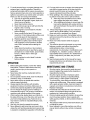
WARNING: - YOUR RESPONSIBILITY: Restrict the use of this power machine to persons who read,
understand and follow the warnings and instructions in this manual and on the machine.
NOTE: Not all safety labels shown may apply to your log spfitters.
V_T]CAL
_i_!i_i!!i!¸¸_
OPERATOR'S INSTRUCTIONS _,_ eP_'_e_'_ _,_
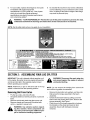
SECTION2: ASSEMBLINGYOURLOGSPLITTER
IMPORTANT: This unit is shipped without gasoline or oil
in the engine. Be certain to service engine with gasoline
and oil as instructed in the separate engine manual
before operating your machine.
NOTE: Reference to right or left hand side of the log
spfitter is observed from the operating position.
RemovingUnitFromCarton
Pry the top, sides, and ends off crate.
Set panels aside toavoid tire punctures or personal
injury.
Remove and discard plastic bag that covers unit.
Remove wheels and loose parts if included with
unit (i.e., operator's manual, etc.)
WARNING: Use extreme caution unpack-
ing this machine. Some components are
very heavy and will require additional peo-
ple or mechanical handling equipment.
_1_ WARNING: Disconnect the spark plug wire
and ground against the engine to prevent
unintended starting.
NOTE: Do not remove the banding from around the
tank until the log splitter is assembled.
Remove the two bolts, lock washers, and hex nuts
that secure the tongue assembly to the beam
assembly.
Unlock the two beam locks by pulling out on the
beam locks and pivoting them down. Remove the
tongue assembly. See Figure 1.
Place the end of the tongue assembly in between
the brackets on the wheel and reservoir tank
assembly. Secure with hardware previously
removed.

Bracket
@
Vertical
Hex
Nuts
Lock
Washers
Tongue
Assembly
Horizontal
Hex
Bolts
Beam Lock
Figure 1
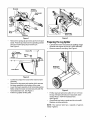
Remove the spring clip and clevis pin from the jack
stand. Pivot the jack stand to the operating position
and secure with spring clip and clevis pin.
See Figure 2.
Figure 3
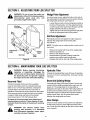
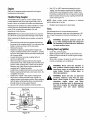
PreparingTheLogSplitter
Lubricate the beam area where the splitting wedge
will slide with engine oil (DO NOT USE GREASE).
Remove reservoir vent plug. See Figure 4.
Clevis Pin -_= P
Tongue
E]_f[ Assembly S rin
_S_
Jack
Figure 2
Cut the two straps from around the reservoir tank
assembly.
Remove the lag screw and washer which secures
the beam assembly to the bottom of the crate.
Lower the beam assembly to its horizontal position.
Make certain the beam is locked securely with the
horizontal beam lock. See Figure 3.
Pull the log splitter off the pallet.
Reservoir
Figure 4
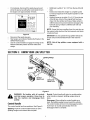
Fill the reservoir tank to the within 3" to 3 1/2" from
the top of fill tube with Dexron III automatic trans-
mission fluid or 10W AW hydraulic fluid.
See Figure 5.
Check fluid level using a scale and do not overfill.
Replace vent plug securely.
NOTE: The reservoir tank has a capacity of approxi-
mately 4 gallons.

If not already, disconnect the spark plug wire and
prime the pump, by pulling the recoil starter to turn
the engine over approximately 10 times.
3"to3 /2"
Maintain fluid
level within 3"
to 3//2" from
fop at all times,
DO not overfill.
Check fluid level using scale, Never run
below this level, Pumg will be ruined.
i2073_
Figure 5
Reconnect the spark plugwire.
Start engine according to Starting the Engine in the
OPERATION section.
Use the control handle to engage the wedge to the
farthest extended position and then retract the
wedge.
Refill tank to within 3"to 3 1/2" from the top of the fill
tube.
Extend and retract the wedge 12 complete cycles
to remove trapped air in the system (system is "self-
bleeding").
Refill the reservoir to within 3" to 3 1/2" from the top
of the fill tube. Much of the original fluid has been
drawn into the cylinder and hoses. Make certain to
refill the reservoir to prevent extreme damage to the
hydraulic pump. Failure to refill the tank will void
your warranty.
NOTE: Some fluid may overflow from the vent plug as
the system builds heat and the fluid expands and seeks
a balanced level.
IMPORTANT: Do not operate the log splitter without the
proper amount of transmission fluid in the reservoir
tank.
NOTE: Not all log splitters come equipped with a
log tray.
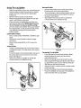
SECTION3: KNOWYOURLOGSPLITTER
Handle
Beam Lock
Beam Lock
Figure 6
WARNING: Be familiar with all controls
and their proper operation. Know how to
stop the machine and disengage them
quickly.
ControlHandle
The control handle has three positions.See Figure 6.
Splitting: Push the control handle forward or down.
Splitting wedge moves toward the end plate.
Neutral: Control handle will return to neutral position
when handle is released. Splitting wedges stops in
place.
Disengage: When pulling the control handle up or
back, the splitting wedge moves toward the cylinder.
The control handle will lock in the disengaged position.
It will return to neutral automatically when the
disengage stroke is complete.

BeamLocks
There are two beam locks one for each operating
position. See Figure 6.
Vertical: The vertical beam lock is located next to the
oil filter.
Horizontal: The horizontal beam lock is part of the
beam support latch bracket.
Starter Handle
The starter handle is located on the engine. Pull the
starter handle to start engine.
EngineControls
See the separate engine manual for the location and
function of the controls on the engine.
StoppingEngine
Move throttle control lever to STOP or OFF
position.
Disconnect spark plug wire and ground against the
engine to prevent unintended starting.
SECTION4: OPERATINGYOURLOGSPLITTER
_lb ARNING: Read, understand, and follow
all instructions and warnings on the
machine and in this manual before
operating.
WARNING: Wear leather work gloves,
safety shoes, and safety glasses when
operating log splitter. Ensure safe footing.
GasAndOilFill-Up
Service the engine with gasoline and oil as instructedin
the separate engine manual packed with your chipper
shredder vacuum. Read instructions carefully.
WARNING: Use extreme care when
handling gasoline. Gasoline is extremely
flammable and the vapors are explosive.
Never fuel machine indoors or while the
engine is hot or running. Extinguish
cigarettes, cigars, pipes, and other
sources of ignition.
StartingEngine
Attach spark plug wire to spark plug. Make certain
the metal cap on the end of the spark plug is
fastened securely over the metal tip on the spark
plug.
Engines with choke lever:
Move choke lever on engine to CHOKE position. (A
warm engine may not require choking).
Engines with primer:
Prime engine as instructed in separate engine
manual.
The throttle control lever is located on the engine.
Move engine throttle control lever to FAST or
START position.
Grasp starter handle and pull rope out slowly until
engine reaches start of compression cycle (rope
will pull slightly harder at this point).
Pull rope with a rapid, continuous, full arm stroke.
Keep a firm grip on starter handle. Let rope rewind
slowly.
Repeat the previous steps until engine fires. When
engine starts, move choke control (if equipped)
gradually to RUN position.
If weather is cold, run wedge up or down beam 6 to
8 times to circulate the hydraulic fluid.
WARNING: When starting a warm engine,
muffle, engine, and surrounding areas
become hot and can cause a burn. Do not
touch.
Always:
Use clean fluid and check fluid level regularly.
Use Dexron III Automatic Transmission Fluid or
10W AW hydraulic fluid.
Use a filter (clean or replace regularly)
Use a breather cap on fluid reservoir.
Keep end of reservoir return tube below fluid level.
Make certain pump is mounted and aligned
properly.
Use a flexible "spider" type coupling between
engine and pump drive shafts.
Keep hoses clear and unblocked.
Bleed air out of hoses before operating.
Flush and clean hydraulic system before starting
after any malfunction or servicing.
Use "pipe dope" on all hydraulic fittings.
Allow time for warm-up before splitting wood.
Prime the pump before initial start-up by turning
over the engine with spark plug disconnected.
Split wood with the grain (lengthwise) only.
Never:
Use when fluid is below 20° F or above 150 ° F.
Use a solid engine !pump coupling.
Operate through relief valve for more than several
seconds.
Attempt to adjust unloading or relief valve settings
without pressure gauges.
Operate with air in hydraulic system.
Use teflon tape on hydraulic fittings.
Attempt to cut wood across the grain.

UsingTileLogSpliUer
Place the logsplitter on level, dry, and solid ground.
Place the beam in either the horizontal or vertical
position and lock in place with the appropriate
locking rod.
Block the front and back of both wheels.
Place the log against the end plate and only split
wood in the direction of the grain.
When necessary to stabilize the log, place your
hand only on sides of log. NEVER place hand on
the end between the log and splitting wedge.
Only one adult should stabilize the logand operate
the control handle, sothe operator has full control
over stabilizing the log and movement of the
splittingwedge.
Control HandlePositions
Move controlhandle FORWARD or DOWN to split
wood.
Release the control handle to stop the wedge
movement.
Move control handle BACK or UP to return the
wedge.
VerticalPosition
Pull the horizontal beam lock out and pivot itdown
to release the beam. Pivot the beam to the vertical
position.
To lock the beam in the vertical position, pull out on
the vertical beam lock and pivot it to secure the
beam. See Figure 7.
Stand in front of the log splitter to operate the
control handle and to stabilize the log.
HorizontalPosition
Pull the vertical beam lock out and pivot it down.
Pivot the beam to the horizontal position.
To lock the beam in the horizontal position, pull out
on the horizontal beam lock and pivot it to secure
the beam. See Figure 8.
Stand behind the reservoir tank to operate the
control handle and to stabilize the log.
Figure 8
TransportingThe LogSplitter
Lower the beam to itshorizontal position.Make
certain the beam is locked securely with the
horizontal beam lock.
Remove the spring clip and clevis pinfrom jack
stand. Support the tongue and pivotthe jack stand
up against the tongue. Secure with the spring clip
and clevis pin previously removed.
Attach the hitchto a towing vehicle, making certain
to latch securely.
Connect the safety chains to the towing vehicle.
Plug in the taillights as instructed in the taillight kit
manual included with your log splitter.
Figure 7

SECTION5: ADJUSTINGYOURLOGSPLITTER
Hex
Bolts
Adj
Bolts
WARNING: Do not at any time make any
adjustments without first stopping engine,
disconnecting spark plug wire, and
grounding it against the engine.
Attached
To Cylinder_.,.._
Plate
Plate
Figure 9
WedgePlateAdjustment
As normal wear occurs, adjust the boltson the side of
the wedge plate to eliminate the excess space between
the wedge plate and beam. See Figure 9.
Loosen thejam nuts on the two adjustment boltson
the side ofthe gib plate. Turn the adjustment bolts
in until snugand then back them off slowlyuntil the
wedge assembly willslide on the beam.
Tighten the jam nuts securely against the gib plate
to hold the adjustment bolts inthis position.
GibPlateAdjustment
Periodically remove and replace the "gibs" (spacers)
between the wedge plate and the back plate.
See Figure 9.
NOTE: The gibs may be rotated and/or turned over for
even wear.
Remove the center bolt on top of the wedge plate.
Slide the gib plate out.
Remove and replace the gibs.
Reassemble the gib plate, making certain flat
washers are in place under the gib plate.
Readjust the bolts on the side of the wedge plate.
SECTION6: MAINTAININGYOURLOG
WARNING: Before cleaning, lubricating,
repairing, or inspecting, disengage the
control lever and stop engine. Disconnect
the spark plug wire and ground it against
the engine to prevent unintended starting.
ReservoirFluid
Check the hydraulic fluid level in the log splitter
reservoir tank before each use. Maintain fluid level
within 3" to 3 1/2" from top at all times. Change the
hydraulic fluid in the reservoir every 100 hours of
operation. Disconnect the suction hose from the bottom
of the reservoir tank and drain the fluid into a suitable
container. Refill using only Dexron III automatic
transmission fluid or 10W AW hydraulic fluid.
Be aware of the environment when disposing of
used petroleum products. Please dispose of used
hydraulic fluid and engine oil at approved recycling
centers.
WARNING: Use extreme caution when
working with kerosene, it is flammable
fluid. Extinguish cigarettes, cigars, pipes,
and other sources of ignition.
SPLITTER
HydraulicFilter
Change the hydraulic filter every 50 hours of operation.
Use only a 10 micron hydraulic filter. Order part number
723-0405.
BeamAndSplittingWedge
Lubricate both sides of the beam (where it comes into
contact with the splitting wedge) before each use with
engine oil. The wedge plate on the log splitter is
designed so the gibs on the side of the wedge plate can
be removed and rotated and!or turned over for even
wear.Make certain to readjust the adjustment bolts so
wedge moves freely, but no excess space exists
between the wedge plate and beam.
HoseClamps
Check the hose clamps on the suction hose (attached
to side of the pump) for proper tightness before each
use. Check the hose clamps on the return hose at least
once a season.
10

Engine
Refer tothe separate engine manual for all engine
maintenance instructions.
FlexiblePumpCoupler
The flexible pump coupler is a nylon "spider" insert,
located between the pump and engine shaft. Over a
period of time, the coupler will harden and deteriorate.
Replacement is needed ifyou detect vibration or noise
coming from the area between the engine and the
pump. If the coupler fails completely, you will
experience a loss of power.
IMPORTANT: Never hit the engine shaft in any manner,
as a blow will cause permanent damage to the engine.
When replacing the flexible pump coupler, proceed as
follows: I_
Remove three nuts and lock washers that secure
the pump to the coupling shield. Two nuts are at the
bottom corners and one is in the top center.
Remove the pump.
Rotate the engine by pulling starter handle until
engine coupling half set screw is at bottom. Loosen
set screw using allen wrench and slide coupling half
off of engine shaft.
Loosen set screw on pump coupling half and
remove coupling half.
Slide new engine coupling half onto the engine
shaft until the end of the shaft is flush with the inner
portion of the coupling half. (There must be space
between end of the engine support bracket and ,_
coupling half). Tighten set screw.
Install pump coupling half and key on pump shaft.
Rotate coupling half until set screw faces down. Do
not tighten set screw.
Install nylon "spider" onto engine coupling half. ,£t
Align pump coupling half with nylon "spider" by
4Jl=
rotating engine using starter handle. Slide coupling
half into place while guiding three mounting bolts
through holes in pump support bracket.
Secure with nuts and washers removed earlier.
Gear Pump
Set
Nylon Steel
Insert Halves
Engine
Figure 10
Set .010" to .060" clearance between the nylon
"spider" and the engine coupling half by sliding a
matchbook cover between the nylon "spider" and
the engine coupling half and moving pump coupling
half as needed. Secure pump coupling half with set
screw. See Figure 10.
NOTE: Make certain proper clearance is obtained
before tightening set screw.
Reattach spark plug wire to spark plug.
Tires
See sidewall oftire for recommended pressure.
Maximum tire pressure under any circumstances is30
p.s.i. Equal tire pressure should be maintained on all
tires.
WARNING: Excessive pressure (over 30
p.s.i.) when seating beads may cause tire/
rim assembly to burst with force sufficient
to cause serious injury.
StoringYourLogSplitter
Clean the unit thoroughly.
Wipe equipment with an oiled rag to prevent rust.
Refer to engine manual for correct engine storage
instructions.
Store unit in a clean, dry area. Do not store next to
corrosive materials such as fertilizer.
WARNING: Never store the machine or
fuel container indoors where there is an
open flame, spark, or pilot light such as on
water heater, furnace, clothes dryer, or
other gas appliance.
WARNING: Drain fuel into an approved
container outdoors, away from an open
flame. Allow engine to cool. Extinguish
cigarettes, cigars, pipes, and other
sources of ignition prior to draining fuel.
Fuel left in engine for extended periods
deteriorates and will cause starting
problems.
11

SECTION7: CONDITIONSTHATWILLVOIDWARRANTY
Failure to maintain proper fluid level in reservoir will
cause permanent damage to pump by allowing air
to be drawn into pump. Fluid will become foamy.
Changing the relief valve setting or pressure
adjustment of control valve without proper
knowledge and instruction from the factory will void
your warranty. A very minor adjustment could
destroy the structural and safety limits for which the
unit was designed. The system will produce more
power than the structure will withstand. Higher
pressure could cause the hoses to burst, cylinder to
rupture, and intense fluid releases, which could
result in serious personal injury.
Disassembling the pump will void your warranty. If
replacement is necessary, merely disconnect and
replace. Do not attempt to adjust pump settings, as
they are adjusted by the manufacturer at the
factory.
Use of incorrect hydraulic fluid will void your
warranty. Use only Dexron III automatic
transmission fluid or 10W AW hydraulic fluid.
The flexible pump coupler must be inspected
regularly. Allowing the coupler to deteriorate will
void your warranty. Deterioration of spider insert
and prolonged use after its deterioration will destroy
pump bearings, engine bearings and the coupler
hubs.
Improper beam lubrication will cause premature
wear and looseness. Lubricate the beam regularly.
Lack of lubrication will void your warranty.
Improper adjustment of splitting wedge will void
your warranty. If wedge is too loose, cylinder beam
and wedge wear will result. Allowing the wedge to
loosen and be used under operating stress will
cause damage which will not be covered under
warranty. If wedge is too tight, severe beam
damage wilt result which will not be covered under
warranty.
Do not overheat the hydraulic system. Excessive
heat will destroy the hydraulic system with
hardened O-rings and excessive friction.
Do not attempt to start in temperatures under 20r_F
without pre-heating fluid in reservoir. Excessively
cold fluid can not circulate and draw into pump.
Repair any leaks in hydraulic system immediately.
Unattended leaks will cause air to enter system
and/or decrease fluid level in reservoir, causing
damage to the hydraulic system which will not be
covered by warranty.
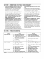
SECTION8: TROUBLESHOOTING
Problem Cause
Engine fails to start
Engine runs erratic
1. Spark plug wire disconnected.
2. Fuel tank empty or stale fuel.
3. Throttle control lever not in correct
starting position. (If Equipped)
4. Choke not in CHOKE position.
(If Equipped)
5. Blocked fuel line.
6. Faulty spark plug.
1. Spark plug wire loose.
2. Unit running on CHOKE.
(If Equipped)
3. Blocked fuel line or stale fuel.
Remedy
1. Connect wire to spark plug.
2. Fill tank with clean, fresh gasoline.
3. Move throttle lever to FAST position.
4. Water or dirt in fuel system.
5. Dirty air cleaner.
6. Carburetor out of adjustment.
1. Engine oil level low.
2. Dirty air cleaner.
3. Carburetor not adjusted properly.
4. Move choke to CHOKE position.
5. Clean fuel line.
6. Clean, adjust gap, or replace.
1. Connect and tighten spark plug wire.
2. Move choke lever to OFF position.
Engine overheats
NOTE: For repairs beyond the minor adjustments listed above, contac_ _our nearest authorized service dealer.
3. Clean fuel line; fill tank with clean, fresh
gasoline
4. Drain fuel tank. Refill with fresh fuel.
5. Clean or replace air cleaner.
6. See authorized service dealer.
1. Fill crankcase with proper oil.
2. Clean or replace air cleaner.
3. See authorized service dealer.
12

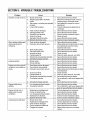
SECTION9: HYDRAULICTROUBLESHOOTING
Problem Cause
Cylinder rod will not move
Stow cylinder shaft speed
while extending and
retracting.
Leaking cylinder
Engine runs but wood wilt
not split or wood splits too
slowly
Engine stalls during
splitting
Engine will not turn or
stalls under low load
conditions
Leaking pump shaft seal
1. Broken drive shaft.
2. Shipping plugs left in hydraulic
hoses.
3. Set screws in coupling not adjusted
properly.
4. Loose shaft coupling.
5. Gear sections damaged.
6. Damaged relief valve.
7. Hydraulic lines blocked.
8. Incorrect oil level.
9. Damaged directional valve.
10. Blocked directional valve.
1. Gear sections damaged.
2. Excessive pump inlet vacuum.
3. Slow engine speed.
4. Damaged relief valve.
5. Incorrect oil level.
6. Contaminated oil.
7. Directional valve leaking internally.
8. Internally damaged cylinder.
1. Broken seals.
2. Scored cylinder.
1. Small gear section damaged.
2. Pump check valve leaking.
3. Excessive pump inlet vacuum.
4. Incorrect oil level.
5. Contaminated oil.
6. Directional valve leaking internally.
7. Overloaded cylinder.
8. Internally damaged cylinder.
1. Low horsepower!weak engine.
2. Overloaded cylinder.
1. Engine/pump misatignment.
2. Frozen or seized pump.
3. Low horsepower/weak engine.
4. Hydraulic lines blocked.
5. Blocked directional valve.
1. Broken drive shaft.
2. Engine!pump misatignment.
3. Gear sections damaged.
4. Poorly positioned shaft seal.
5. Plugged oil breather.
Remedy
1. See authorized service dealer.
2. Disconnect hydraulic hoses, remove
shipping plugs, reconnect hoses.
3. See operator's manual for correct
adjustment.
4. Correct engine/pump alignment as
necessary.
5. See authorized service dealer.
6. See authorized service dealer.
7. Flush and clean hydraulic system.
8. Check oil level.
9. See authorized service dealer.
10. Flush and clean hydraulic system.
1. See authorized service dealer.
2. Make certain pump inlet hoses are clear
and unblocked-use short, large
diameter inlet hoses.
3. See authorized service dealer.
4. See authorized service dealer.
5. Check oil level.
6. Drain oil, clean reservoir, and refill.
7. See authorized service dealer.
8. See authorized service dealer.
1. See authorized service dealer.
2. See authorized service dealer.
1. See authorized service dealer.
2. See authorized service dealer.
3. Make certain pump inlet hoses are clear
and unblocked.
4. Check oil level.
5. Drain oil, clean reservoir, and refill.
6. See authorized service dealer.
7. Do not attempt to split wood against the
grain.
8. See authorized service dealer.
1. See authorized service dealer.
2. Do not attempt to split wood against the
grain or see authorized service dealer.
1. Correct alignment as necessary.
2. See authorized service dealer.
3. See authorized service dealer.
4. Flush and clean hydraulic system.
5. Flush and clean hydraulic system.
1. See authorized service dealer.
2. Correct alignment as necessary.
3. See authorized service dealer.
4. See authorized service dealer.
5. Make certain reservoir is properly
vented.
13

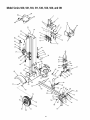
ModelSeries500,501,510,511,530,550,560,and561
19 6_
20 _ 18
11
24
25_
40
\
78
74
58
46
60
5
35
15
48
56
"31
C
16
77
8O
14

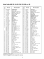
ModelSeries500,501,510,511,530,550,560,and561
Re_
Part No.
No.
1. 781-0323B
2. 712-0239
3. 710-1018
4. 736-0192
5. 710-0459A
6. 781-0356
7. 781-0351
8. 712-0711
9. 750-0743
750-0750
10. 781-0537
11. 781-0352A
12. 781-0350A
13. 736-0921
14. 712-0239
15. 781-0168A
16. 712-0130
17. 710-0859
18. 681-0102
681-0093
681-0127
681-0126
19. 714-0211
20. 711-1135
21. 718-0306
22. 727-0471
23. 727-0443
24. 726-0132
25. 737-0153
26. 737-0192
27. 718-0481
28. 727-0235
29. 737-0316
30. 723-0405
31. 727-0502
32. 714-0470
33. 738-0805
34. 726-0214
35. 732-0583
36. 736-0116
37. 781-0690
38. 737-0236
39. 681-0176
40. 681-0138
41. 710-0157
Ref.
Part Description No. Part No.
Wedge Assembly 42. 736-0159
Lock Nut 1/2-20 43. 736-0119
Hex Cap Screw 1/2-20 x 2,75 44. 712-0123
Flat Washer ,531 ID x ,93 OD 45. 710-0654A
Hex Cap Screw 3/8-24 x 1,5 46. 726-0174
Floating Gib Plate 47. 735-0256
Adjustable Gib 48. 710-1338
Hex Jam Nut 3/8-24 49. 714-0122
Spacer 50. 718-0686
Spacer t 51. 719-0353
Back Bracket 52. 736-0119
Adjustable Gib Shim 53. 712-0123
Fixed Gib 54. 781-0097
Lock Washer 1/2 55. 718-0683
Lock Nut 1/2-20 56. 737-0329
Stripper Side 57. 710-0521
Lock Nut 3/8-16 58. 712-0798
Hex Cap Screw 3/8-16 x 2,5 59. 736-0169
Beam Assembly 60. 710-0411
Beam Assembly (w/o Tray) 62. 681-0110
Beam Assembly t 63. 781-0680A
Beam Assembly (w/o Tray) 64. 736-0185
Cotter Pin 65. 712-0375
Clevis Pin 66. 711-0813
Hydraulic Cylinder 67. 732-0194
Hydraulic Tube 68. 750-0497
Return Hose 3/4" ID x 44" Lg. 69. 710-0944
Hose Clamp 5/8" 70. 736-0262
Return Elbow 71. 713-0433
90 Degree Solid Adapter 72. 727-0311
Control Valve 73. 781-0162
3/4" Hose Adapter 74. 721-0168
Filter Housing 75. 741-0987
Oil Filter 76. 634-0186
High Pressure Hydraulic Hose 77. 634-0180
Cotter Pin 78. 736-0351
Hinge Pin 1/2 x 4,8" 79. 712-0359
Push Cap 80. 714-0162
Compression Spring 4" 81. 734-0873
Flat Washer ,635 ID x ,93 OD 82. 781-0686
Locking Rod 83. 712-0431
Pipe Plug 84. 781-0682
Frame Assembly 4,0 Gal 85. 710-3097
Fender Assembly t 86. 781-0526
Hex Cap Screw 5/16-24 x ,75 t 87. 781-0538
Part Description
Washer 5/16 t
Lock Washer 5/16 t
Hex Nut 5/16-24 t
Hex Washer Screw 3/8-16 x 1.0
Hose Clamp
Suction Hose
Hex Screw 5/16-24 x 3.25
Square Key 3/16" x .75
Flexible Coupling
Coupling Shield
Lock Washer 5/16" ID
Hex Nut 5/16-24
Rear Coupling Support Bracket
Gear Pump (1lgpm)
45 Degree Elbow
Hex Bolt 3/8-16 x 3"
Hex Nut 3/8-16
L-Washer 3/8"
Hex Bolt 3/8-16 x 4"
Support Beam Assembly
Tube
Flat Washer 3/8
Hex Lock Nut 3/8-16
Clevis Pin 5/16 x 2,5"
Spring Pin
Spacer 3/8" ID x .625" OD
Hex Bolt 3/8-16 x 4"
Flat Washer 3/8" ID x ,87" OD
Chain
Hitch Coupler
Jack Stand
Bearing Seal
Bearing Cone
Wheel Assembly
Rim Assembly
Flat Washer .76" ID x 1.5" OD
Slotted Nut 3/4-16
Cotter Pin 5/32" x 1-1/4"
Hub Cap
Log Tray Bracket
Flanged Lock Nut 3/8-16
Log Tray
Carriage Bolt 3/8-16 x 1,0
Hose Guard t
Hose Guard t
t Models 530, 550, 560, and 561
Note: Not all log splitters come equipped with a log tray.
15

MANUFACTURER'S LIMITED WARRANTY FOR:
YARD
The limited warranty set forth below is given by MTD
PRODUCTS INC ("MTD") with respect to new merchandise
purchased and used in the United States, its possessions
and territories.
MTD warrants this product against defects in material and
workmanship for a period of two (2) years commencing on
the date of original purchase and will, at its option, repair or
replace, free of charge, any part found to be defective in
material or workmanship. This limited warranty shall only
apply if this product has been operated and maintained in
accordance with the Operator's Manual furnished with the
product, and has not been subject to misuse, abuse, com-
mercial use, neglect, accident, improper maintenance,
alteration, vandalism, theft, fire, water or damage because
of other peril or natural disaster. Damage resulting from the
installation or use of any accessory or attachment not
approved by MTD Products Inc. for use with the product(s)
covered by this manual will void your warranty as to any
resulting damages.
Normal wear parts or components thereof are subject to
separate terms as follows: All normal wear part or compo-
nent failures will be covered on the product for a period of
90 days regardless of cause. After 90 days, but within the
two year period, normal wear part failures will be covered
ONLY IF caused by defects in material or workmanship of
OTHER component parts. Normal wear parts and compo-
nents include, but are not limited to. belts, blades, blade
adapters, grass bags, rider deck wheels, seats, snow
thrower skid shoes, shave plates and tires. Batteries are
covered by a 90-day limited replacement warranty.
HOW TO OBTAIN SERVICE: Warranty service is available,
WITH PROOF OF PURCHASE THROUGH YOUR LOCAL
AUTHORIZED SERVICE DEALER. To locate the dealer in
your area, please check for a listing in the Yellow Pages or
contact the Customer Service Department of MTD PROD-
UCTS INC by calling 1-800-800-7310 or writing to RO. Box
368022, Cleveland. Ohio 44136-9722.
This limited warranty does not provide coverage in the
following cases:
a, The engine or component parts thereof, These items
carry a separate manufacturer's warranty. Please refer
to the applicable manufacturer's warranty on these
items.
b. Log splitter pumps, valves and cylinders have a sepa-
rate one year warranty.
c. Routine maintenance items such as lubricants, filters,
blade sharpening and tune-ups, or adjustments such
as brake adjustments, clutch adjustments or deck
adjustments; and normal deterioration of the exterior
finish due to use or exposure.
d. MTD does not extend any warranty for products sold
or exported outside of the United States of America,
its possessions and territories, except those sold
through MAD's authorized channels of export distribu-
tion.
No implied warranty, including any implied warranty of
merchantability or fitness for a particular purpose,
applies after the applicable period of express written
warranty above as to the parts as identified. No other
express warranty or guaranty, whether written or oral,
except as mentioned above, given by any person or
entity, including a dealer or retailer, with respect to any
product shall bind MTD. During the period of the War-
ranty, the exclusive remedy is repair or replacement of
the product as set forth above. (Some states do not
allow limitations on how long an implied warranty lasts, so
the above limitation may not apply to you.)
The provisions as set forth in this Warranty provide the
sole and exclusive remedy arising from the sales. MTD
shall not be liable for incidental or consequential loss
or damages including, without limitation, expenses
incurred for substitute or replacement lawn care ser-
vices, for transportation or for related expenses, or for
rental expenses to temporarily replace a warranted
product. (Some states do not allow the exclusion or limita-
tion of incidental or consequential damages, so the above
exclusion or limitation may notapply to you.)
In no event shall recovery of any kind be greater than the
amount of the purchase price of the product sold. Alteration
of the safety features of the product shall void this War-
rarity. You assume the risk and liability for loss, damage, or
injury to you and your property and/or to others and their
property arising out of the use or misuse or inability to use
the product.
This limited warranty shall not extend to anyone other than
the original purchaser, original lessee or the person for
whom it was purchased as a gift.
How State Law Relates to this Warranty: This limited
warranty gives you specific legal rights, and you may also
have other rights which vary from state to state.
-
 1
1
-
 2
2
-
 3
3
-
 4
4
-
 5
5
-
 6
6
-
 7
7
-
 8
8
-
 9
9
-
 10
10
-
 11
11
-
 12
12
-
 13
13
-
 14
14
-
 15
15
-
 16
16


MTD 24AB561D352 Owner's manual
- Category
- Log splitters
- Type
- Owner's manual
- This manual is also suitable for
Ask a question and I''ll find the answer in the document
Finding information in a document is now easier with AI
Related papers
-
Troy-Bilt 550 Series Owner's manual
-
Troy-Bilt 550 Series Owner's manual
-
-
-
-
MTD Series 580 Owner's manual
-
-
-
Yard Machines 585 Owner's manual
-
Other documents
-
Troybilt 24AF572B063-2002 Owner's manual
-
Troy-Bilt LS338 User manual
-
-
Remington RM23 Sequoia User guide
-
Cub Cadet LS 25 CC User guide
-
Bolens 350 User manual
-
Troy-Bilt Log Splitter 570 User manual
-
White Outdoor Series 510 User manual
-
-
Sears 247.34625 User manual